SUPATRAC Blackbird Installation instructions manual

Instructions • Warranty
Blackbird
SUPATRAC
supatrac.com

1
SUPATRAC Blackbird
Thank you for choosing SUPATRAC
Blackbird, a revolutionary tone arm for
high-performance turntables.
The Blackbird is a Sideways Uni-Pivot Arm
(SUPA - patent pending) with a single point
bearing which firmly opposes the drag on
the stylus so that the energy and timing of
musical recordings is reproduced with
exquisite accuracy.
This manual explains how to install and set
up your Blackbird Sideways Uni-Pivot Arm
for best performance.
INDEX
Diagrammes page 2
Box contents page 4
Carriage page 4
Installation page 5
Set-up page 13
Maintenance page 17
Solving problems page 19
Disassembly page 20
Further information page 20
Warranty page 21

2
SUPATRAC Blackbird
Parts and Their Names
hoist pipe
hoist pipe eye
pipe lock screw
pivot bolt
pivot point post
pillar
HAZARD WARNING:
SHARP EDGES - USE
GLOVES PROVIDED
TO AVOID INJURY
base
pillar
arm tube
headshell
counterweight
right hoist
post
thrust box
bias rig
finger lifter
pivot bolt
3
spool tightener
pivot lock nut
hoist spool
pivot bolt
spool clamp
rest magnets
hoist
spool
DANGER WARNING:
SMALL MAGNETS -
KEEP AWAY FROM
CHILDREN
base
pillar
arm tube
headshell
counterweight
right hoist
post
thrust box
bias rig
finger lifter
pivot bolt

BOX CONTENTS
Tone-arm
Pillar & base
Counterweight
Inertia adjuster
Base bolts
Heavy bias weight
Cable
Downforce scale
Rigid finger-lifter
Spare filaments and toggles
Safety gloves
3 Allen keys
Spanner
Screwdriver
Tweezers
Protractor
Instructions & warranty
CARRIAGE
To transport a turntable short distances
with your Sideways Uni-Pivot Arm attached
it is recommended that you…
1. place a folded handkerchief or other
cushion between the pivot point and
thrust plate
2. stabilise the arm with a support or tape
3. attach a stylus guard
For longer journeys it is recommended that
you remove the arm from the post so that it
can be packed separately. See the section
on ‘Disassembly’.
4
INSTALLATION
Install Base
Attach the base to the arm board or plinth
of your turntable using the M5 bolts
provided. The base should be tightly
coupled to the arm board, but not so tight
as to mark or damage it.
If you need longer or shorter bolts, M5 steel
bolts are easily obtained.
5
base
base bolts

Install Pillar
Insert the pillar into the base, taking care
not to drop it. The post or bias rig can safely
be held up with one hand while locking the
pillar with the other.
Orient the post so that the pivot points
away from the last track of a record and is
level with the platter surface. Gently
tighten the pillar-locking bolt. Do not over-
tighten as this will not improve
performance and may dent the pillar.
Install Electrics
Place a handkerchief on the rear of the base
as a cushion for the thrust box. Sit the arm
pillar
pillar locking bolt
base
bias rig
post
6
in position and lift the headshell end to
point upwards so that arm wire plugs can
be pushed onto the connector pins inside
the pillar using the supplied tweezers. Take
care not to strain or snag the wires as they
are necessarily light and therefore fragile.
The positions of the pins are shown in the
diagramme below:
Install Hoists
Insert the hoist toggles into the 4mm holes
on the thrust-box to the left and right of the
pivot point, and ensure that they are fully
through the holes and snagged. The left
hoist toggle is attached to the left hoist and
the bias pulley thread, which passes
through the bias rig.
R- R+
L- L+
Red
Green
Yellow
Blue
White
7
left hoist
toggle
left hoist hole

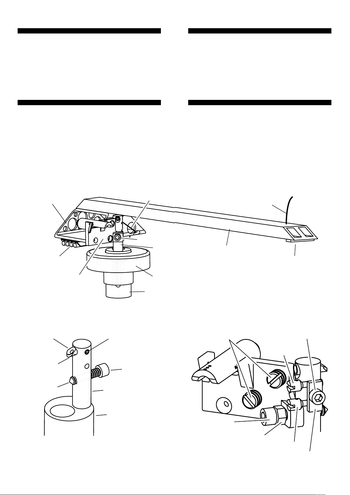
The right hoist toggle is attached only to the
right hoist. Allow the arm to rest gently
against the post, and tighten the spools so
that the arm is suspended level, and the
pivot point makes contact with the thrust
box exactly on the straight line between the
points where the hoists make contact with
the hoist holes.
Install Counterweight
The magnetic counterweight attaches
under the thrust box and can be slid
forwards and backwards to adjust the
downforce at the stylus end. Take care to
restrict movement of the arm while
adjusting the counterweight.
Use the supplied scale to set the required
downforce (see Set-up: Downforce). A 9g
inertia ('effective mass') adjuster is also
included, so be sure to set downforce after
placing the inertia adjuster on the arm in
the desired position.
Adjusting the inertia to suit the suspension
of your cartridge is an important way to
optimise the performance. Compliant
cartridges need a less inert arm, and stiffer
cartridges, a more inert. Satisfactory
right hoist
toggle
right hoist hole
8
results can be achieved by trial and error,
or by calculation. Blackbird has an effective
mass of 11g without the inertia adjuster.
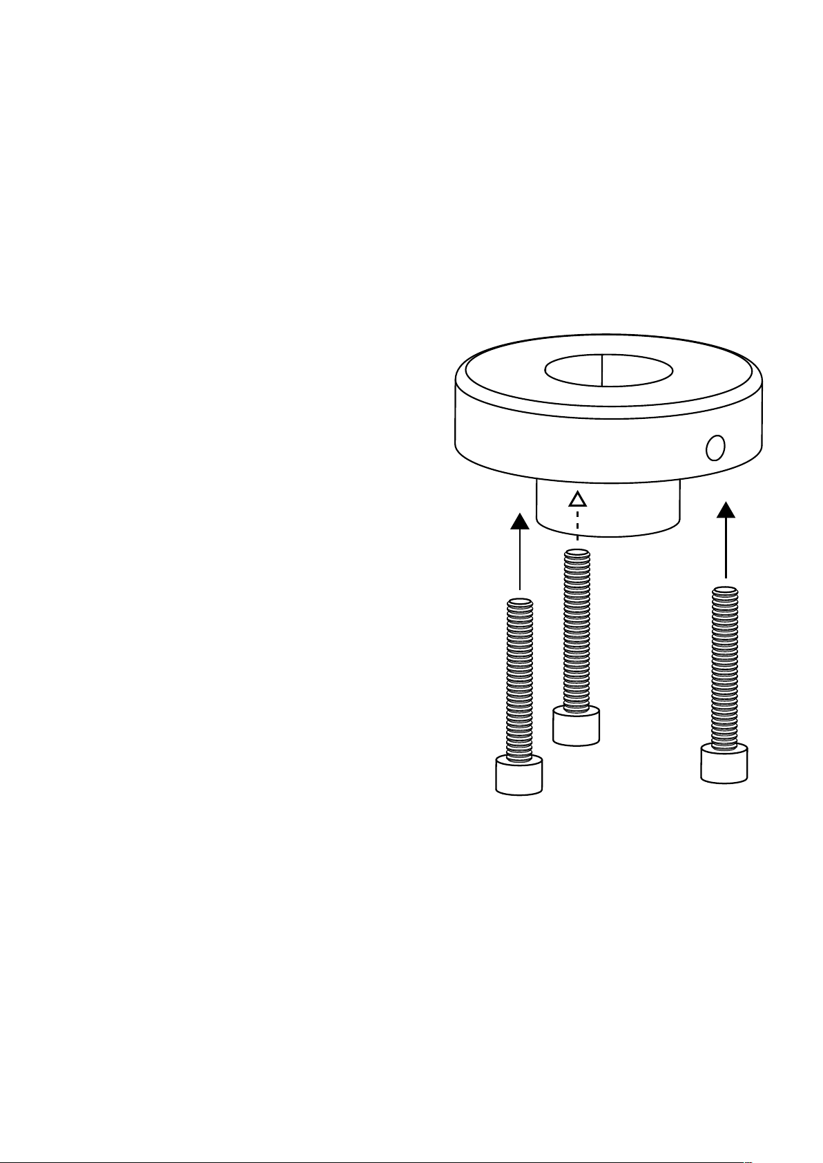
Install Cartridge
Two-bolt cartridges can be installed in the
normal way. Placing a folded handkerchief
between the pivot point and thrust box
protects the pivot point. It is therefore not
necessary to dismount the arm for
cartridge installation. For a three-bolt
cartridge, remove the finger-lifter before
installing the cartridge and use the finger-
lifter hole to insert Allen key or screwdriver
when tightening the third cartridge bolt.
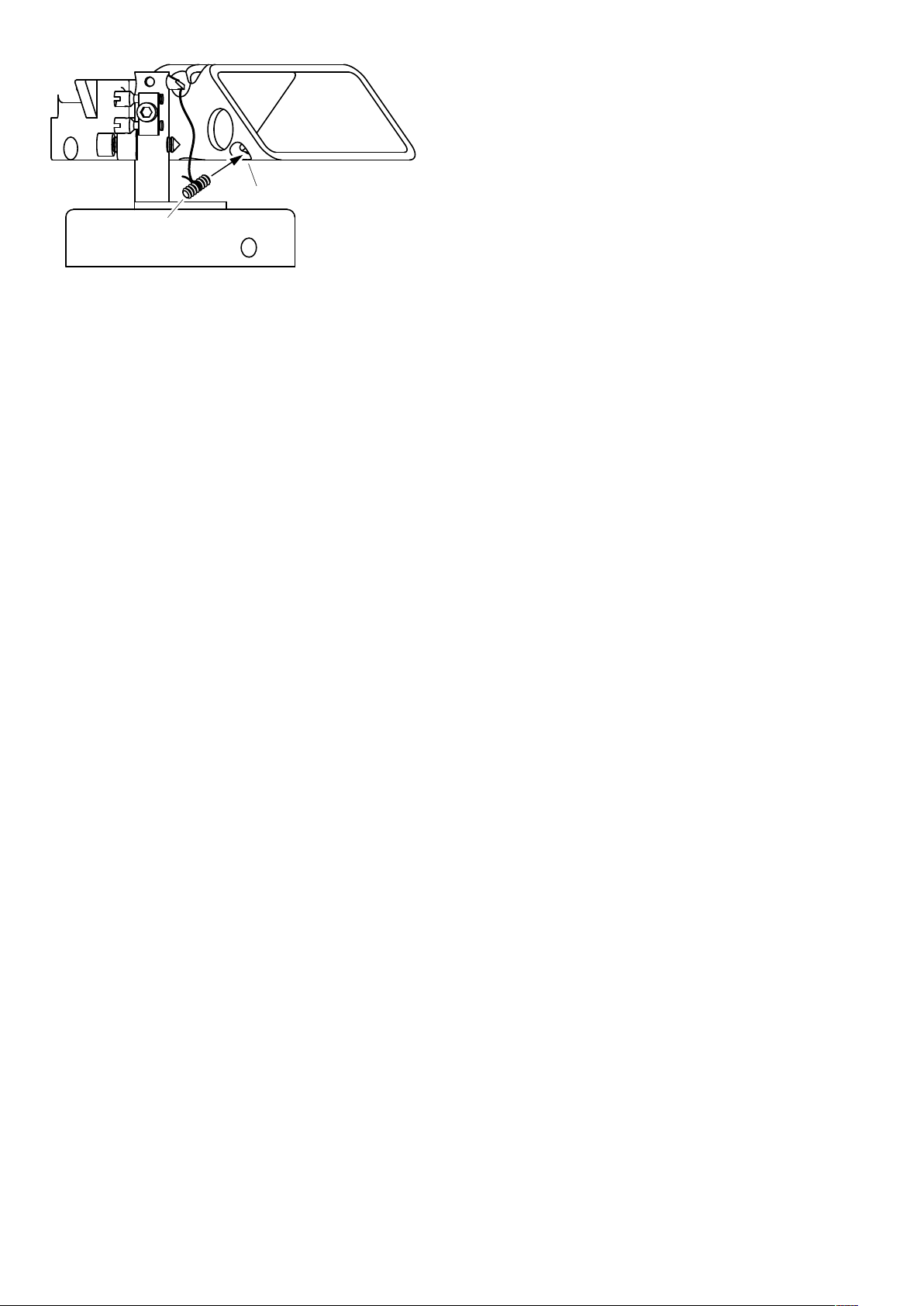
Remove String-lifter
You should be less likely to lose control of
the arm and less likely to damage your
records or cartridge with the string-lifter,
so it is recommended. A firm grip on the
string can be gained without applying
significant sideways or downwards forces
on the cartridge suspension.
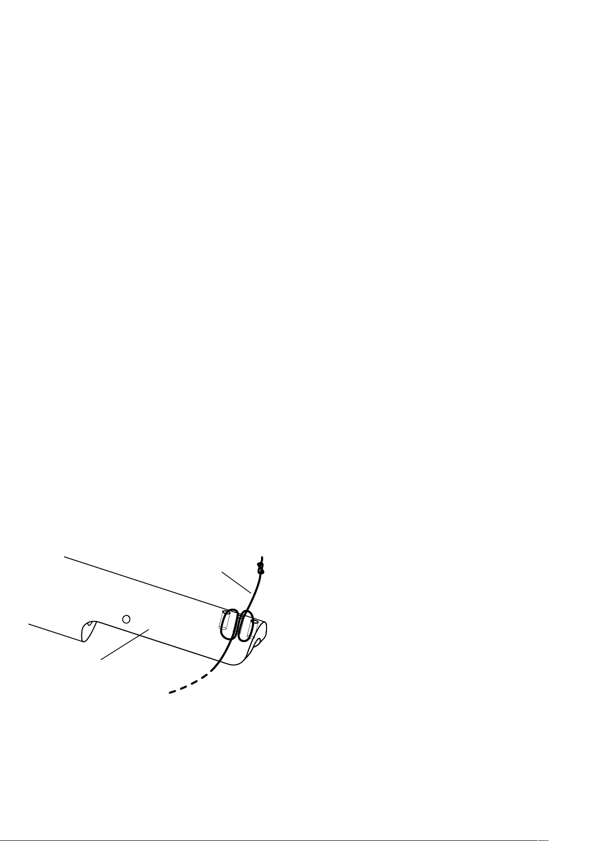
However, if you wish to remove the string
finger-lifter and replace it with the
supplied rigid finger-lifter, use tweezers to
pull the knot at the base of the string out
from inside the arm tube, untie the knot,
and pull through.
Install Rigid Finger-lifter
To bolt the rigid finger-lifter in place, use a
sticky putty or a small loop of tape, sticky-
side-out, on the end of a screwdriver and
9

hold the nut in position inside the arm tube
to receive the countersunk M3 bolt. Once
the nut and bolt have engaged, insert a flat
screwdriver end between the nut and the
inner wall of the arm tube to lock the nut so
that you can tighten the bolt. Do not over-
tighten as this could damage the fragile
carbon-fibre arm tube.
Set Bias
The bias force (also known as ‘anti-skate’) is
adjusted in three ways.
First, the difference between applied bias at
the start and end of the record is adjusted
by shortening or lengthening the bias
pulley. Bias force varies more between the
rotor’s 11 o'clock and 12 o'clock positions
than between 9 o'clock and 10 o'clock.
Shortening the pulley will increase the
range of applied bias. To shorten it, pull at
the loose end when the arm is at rest.
Lengthen it by cuing the arm beyond the
last track of the record or further.
Always lengthen the pulley enough to
ensure that the bias rotor does not reach
the vertical position before the end of
playback. A figure-of-eight pattern through
10
bias rotor
bias pulley
the bias rotor’s three holes, as illustrated, is
normally enough to grip the bias thread but
allow it to slip when forced.
The overall amount of bias is set by
tightening or loosing the grub screw inside
the rotor. The further the grub screw is
from the rotor’s axle, the more bias will be
applied. Do not tighten as far as the axle.
Finally, it is possible to adjust bias by
rotating the pillar in the base if you have
difficulty reaching correct bias by the
above methods.
Arm-Rest Magnets
In the rest position the thrust box attaches
to one, two, or three magnets in the bias rig,
which can be advanced or withdrawn using
a screwdriver to achieve a stable arm-rest
position. One magnet in the outer position
is often adequate, but adding a second or
third magnet in the other holes can help to
achieve a stable rest position.
Alignment
SUPATRAC’s ‘SUPATRACTOR’ is included to
make it easy to establish optimal spindle-
to-pivot distance, cartridge overhang and
null point alignment.
If it is difficult to set these distances
optimally on your turntable, you can
slightly adjust spindle-to-pivot distance by
withdrawing or extending both the pivot
bolt and hoist pipe in equal measure. If this
is done, the pillar and post will no longer be
11

geometry-conservative with regard to
orientaion, and configurations involving
large rotations of the arm pillar will alter
the spindle-to-pivot distance. Please refer
to online geometry calculators or your own
calculations as the broad subject of arm
geometry optimisation is capable of
lengthy discussion.
12
SET-UP & FINE-TUNING
As with other tone arms, inaccurate
configuration can produce poor results,
whereas precise tuning will enable you to
get the best from your records.
Please ensure that your turntable is level
before fine-tuning.
As the suspension settles in, it is worth
regularly checking bias, suspension height,
lean (‘azimuth’) and adjusting the arm’s
geometry to ensure that all are optimal.
Downforce & Inertia
Set downforce and inertia using the
counterweight which attaches
magnetically to the underside of the thrust
box, and the inertia adjuster which sits
across the arm like a saddle between the
cartridge and pivot. The further both
weights are from the pivot, the higher will
be the arm’s inertia (‘effective mass’). High
compliance cartridges work better with low
inertia, whereas low compliance cartridges
work better with higher inertia.
Downforce Scale Use
Place the supplied downforce scale on the
platter. The coin-sized rebates
accommodate a UK penny, a US cent or a
Euro centime as the balancing weight. The
dimples represent 1/10 gram increments in
the range 1.2g - 4g. Adjust the counter-
weight until the scale balances with your
13

neutralises the net sideways playback
forces on the stylus.
Recommended ways of judging bias are:
1. looking at the cantilever exactly head-
on while music is playing
2. observing whether the arm moves
centripetally or centrifugally when the
stylus is lowered onto the flat surfaces
between the grooves
3. listening for balance across speakers
with passages which are difficult to
track or with a test/set-up record
Vertical Tracking Angle
Vertical tracking angle can be set by raising
or lowering the pillar. Take care to support
the pillar while loosing the locking screw in
the side of the base as there is no brake.
Slide the pillar up or down and gently
tighten the locking screw. The tightness of
the locking screw can affect the sound, so
adjust it to taste, remembering that tighter
is often not better.
Suspension Height and
Cartridge Lean
Lean, commonly, but confusingly called
‘azimuth’, is the extent to which the
cartridge leans towards the centre of the
record or away from it. Zero lean is
important for accurate playback and
stylus/record longevity. Lean can be
adjusted by shortening or loosing the left
and right hoists using the hoist spools.
15
stylus resting in the dimple corresponding
to your desired downforce.
Blackbird’s low pivot means that your
stylus should maintain contact with the
record even at minimum recommended
downforce, or lower. Consistent tracking
with low downforce can reduce wear on
records and styluses.
Bias Tuning
Bias is required to ensure that both sides of
the stylus have roughly equal contact
pressure with records even though they
pull the arm at an angle (‘offset’).
Ensure that the electric wiring is free and
clear and not constraining arm movement
before setting bias.
Bias is supplied by the bias rotor, which
pulls a polyester thread attached to the left
hoist toggle. The force is adjusted by
screwing the bias weight grub screw into
the bias rotor. A heavier grub screw (M6) is
also supplied. The difference (ratio)
between the bias at the start and end of a
record can be changed by shortening or
lengthening the bias thread (see
installation). After adjusting the ratio it
may be necessary to adjust the bias weight
again. Repeat until bias across the record is
roughly appropriate.
Exact bias is dependent on signal strength,
record speed and many other factors, so
aim for a level of bias which roughly
14

MAINTENANCE
ROUTINE CHECKS
Hoists
Look for fraying of the hoists at flexion
points like the hoist pipe eye, which can
indicate that they are ready for
replacement. They should last a long time
with normal use, and if they look to be in
sound condition then there is no need to
change them.
When replacing hoists, use the bend of a
slip knot around the hoist toggles, and a
boom hitch around the spools.
Pivot point
It is not clear whether or how a severely
blunted pivot point might compromise
performance, since pressure against the
pivot is always maintained by gravity.
However, it is very easy to replace the pivot
bolt with a newly-sharpened one. Contact
Supatrac for more information.
Thrust Box Bolts
After long periods check that the bolts
which attach the arm to the thrust box are
17
boom hitch
IMPORTANT: there is a correct height for
the suspended arm: the pivot point must
make contact with the thrust box on the
straight line between the two points
where the hoists meet the thrust box.
To ensure this, cut a 6cm by 1cm rectangle
from the corner of a straight-edged piece of
paper, insert it between the hoists and the
thrust box and raise the headshell so that
the paper’s straight edge sits on the points
where the hoists meet the thrust box. The
pivot contact should occur at or just below
the paper’s edge.
Once the correct height is set, lean can be
adjusted by shortening and lengthening the
two hoists in equal and opposite measure so
that the pivot contact remains on the line
between the suspension points. Always
check that the pivot contact lies on this line
after adjustments by resettling the
suspension and applying the paper test
again. A period of incremental adjustments
to suspension height may help to establish
optimal performance.
16
pivot bolt
straight edge
paper
hoists
thrust box

SOLVING PROBLEMS
Inconsistent Lean
When the arm is new, or when adjustments
are made, lean can appear to vary slightly
between the start and end of a record. This
will normally pass as the hoists settle in and
form to the shape of the hoist pipe.
If this persists, it may result from under-
extension of the hoist pipe eye relative to
the pivot point. To extend the hoist pipe,
dismount the arm, loosen the pipe locking
screw and push the hoist pipe a little
further out so that its eye is more directly
above the pivot point. The bearing works
best if the eye of the hoist pipe is only a
millimetre or so closer to the post than the
pivot point. Do not over-extend the hoist
pipe lest contact at the pivot cease.
Excess Bias
This problem may also arise from the eye of
the hoist pipe being too near the post as
compared to the pivot. Extend the hoist
pipe as described above.
hoist pipe
hoist pipe eye
pipe lock screw
pivot bolt
pivot point post
pillar
19
gripping tightly. Do not overtighten as this
could split the carbon-fibre tubes. The short
end of an Allen key can be ground down in
order to access the thrust box bolts with it.
18

supatrac.com
20
DISASSEMBLY
To disassemble, reverse the installation.
1. Protect your stylus with a guard.
2. Gently lift the arm to raise it and use the
tweezers to feed the left and right hoist
toggles through the hoist holes in the
thrust box, being careful not to tug the
electrical connections destructively.
3. Use the tweezers to unplug the electrical
contacts by gripping the plugs with
tweezers, not the wires, and gently pull
them upwards until they detach.
4. The arm is now detached and can be
stored somewhere safe.
5. Unplug the arm cable from the bottom of
the pillar.
6. Loosen the pillar locking bolt, taking care
not to allow the pillar to drop, and remove
the pillar.
7. Unbolt the base.
FURTHER INFORMATION
For further information, please visit
www.supatrac.com
SUPATRAC tone-arms are designed and
made by hand in Chelsea, London, England.
© SUPATRAC 2021
Table of contents
Other SUPATRAC Turntable manuals