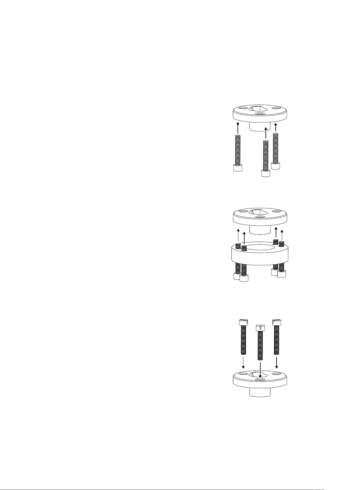
Remove Transport Bolt
Once the arm is installed on the turntable and
the pillar is secure, you can unscrew the
transport bolt and remove the transport spacer.
Take care not to strain or abrade the electrical
wires and hoists when removing the spacer. It
can help to lift the whole arm upwards a little
while keeping it level.
If None, Install Cartridge
If you did not install your cartridge before
mounting the arm, place a folded tissue
between the pivot and thrust box to protect
them during cartridge installation.
For a three-bolt mounting, remove the finger-
lift and use its hole to access the third bolt with
an Allen key or screwdriver.
Large head cartridge bolts or large nuts will not
fit in the headshell. It is possible to file large
bolt-heads and nuts in a drill or by hand.
Contact SUPATRAC if you are unable to
procure compatible bolts.
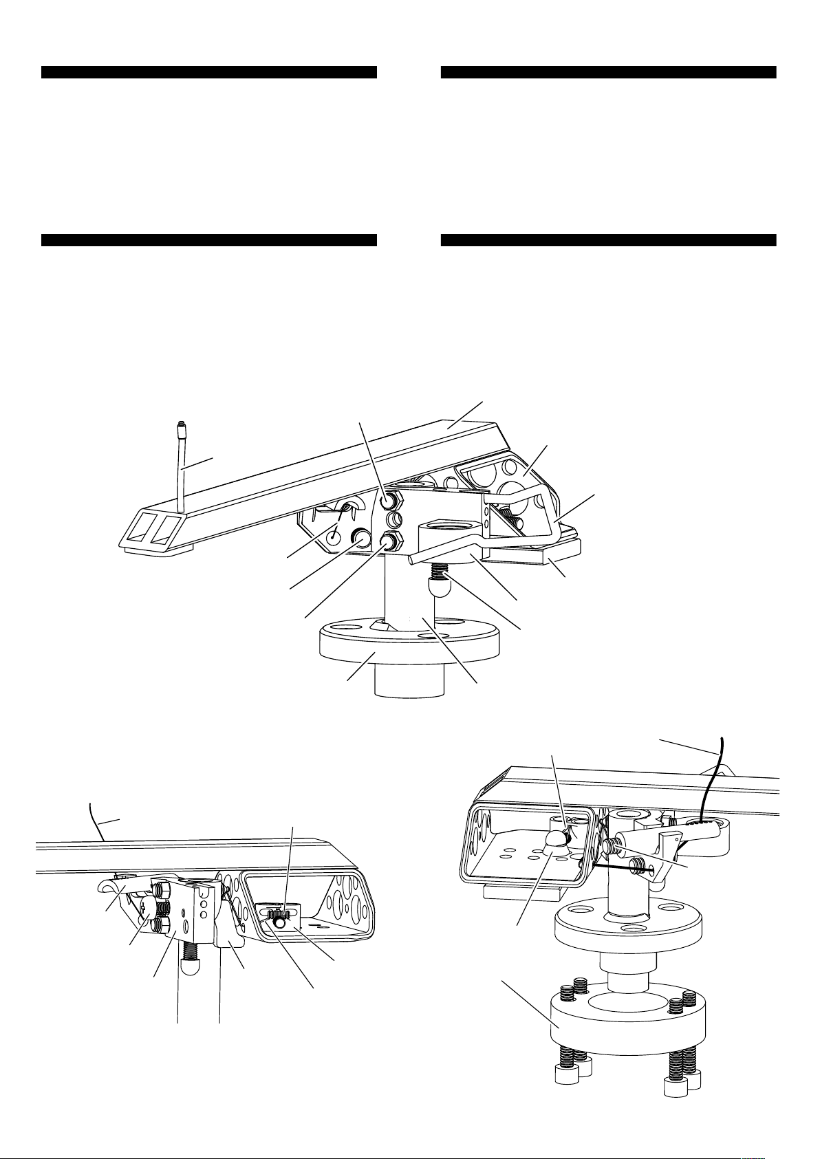
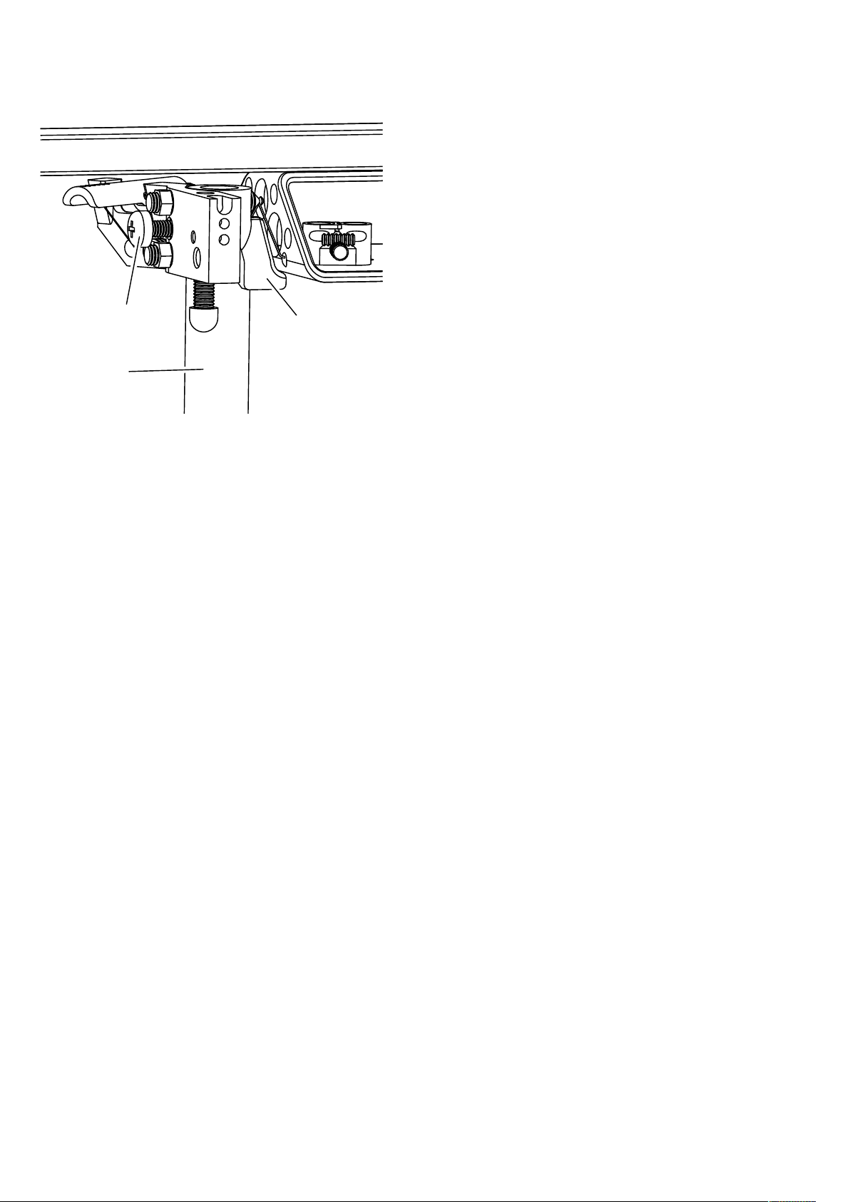
Attach Counterweight
When setting downforce, always obstruct
movement of the arm by holding it in your left
hand while adjusting the counterweight with
your right. Attach a magnetic counterweight
under the thrust box and squeeze it forwards
for more downforce or backwards for less. Keep
the counterweight centred on the axis of the
arm by pinching the thrust box from both sides
between thumb and fingers. You can centre the
counterweight by feel. Very small adjustments
of counterweight from left to right allow very
fine adjustment of lean (azimuth).
Multiple counterweights are supplied to cater
for a wide range of cartridge weights,
compliances and tracking weights (downforces).
To measure downforce, place the supplied
downforce scale on the bare platter with either
a penny, a cent or a centime as a balancing
weight in the appropriate bed. The dimples in
the scale represent 1/10 gram increments in the
range 1.2g - 4g. Adjust the counterweight until
the scale almost balances with your stylus
resting in the dimple corresponding to your
desired downforce.
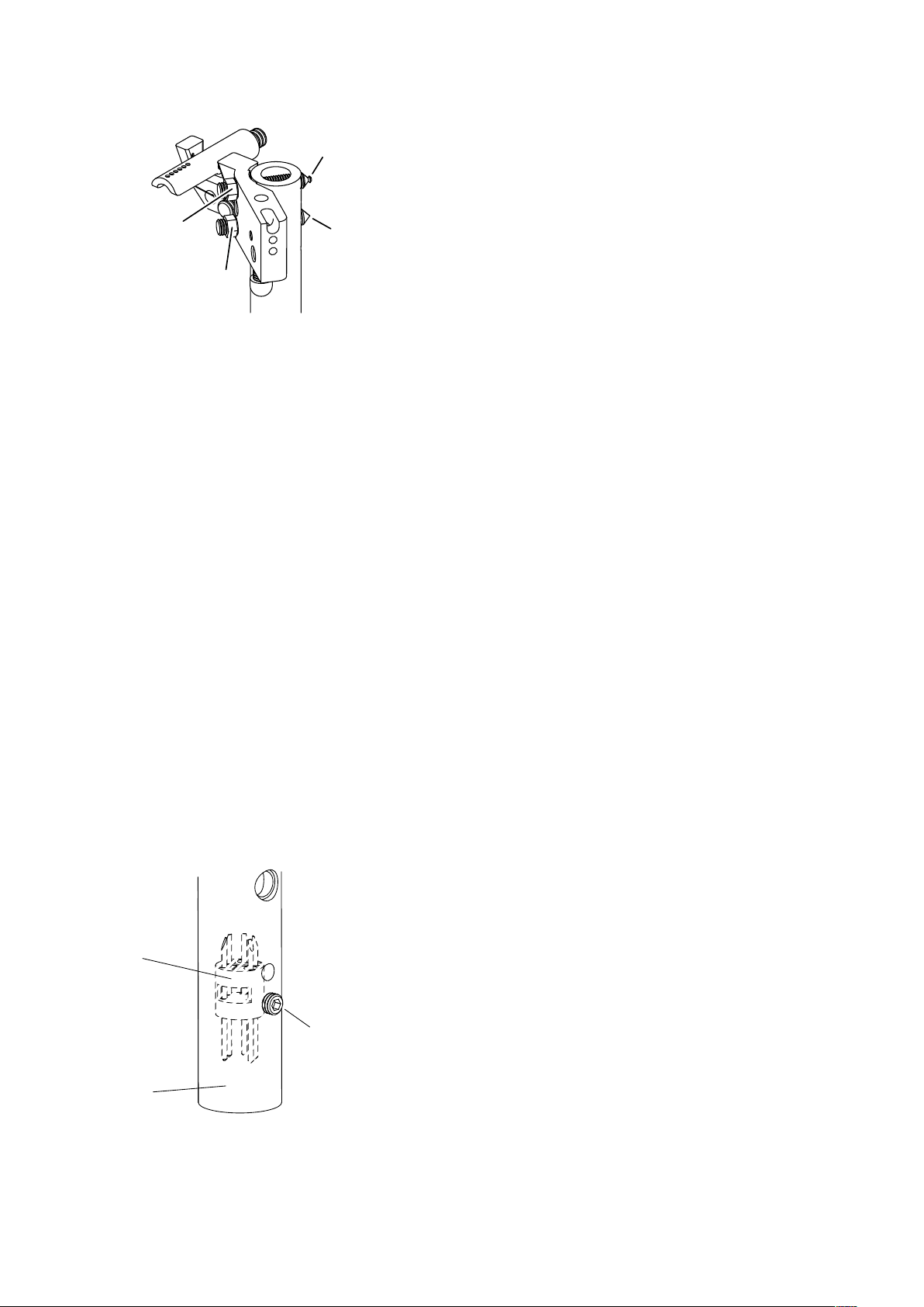
Level Arm (VTA)
The ‘Vertical Tracking Angle’ or arm level can be
set by raising or lowering the pillar. Take care to
set the arm level control screw to an
appropriate height. Guide the pillar up or down
using the level control screw and tighten the
pillar locking screw gently. The tightness of the
pillar locking screw can affect the sound, so
adjust it to taste. Tighter may not be better.
It may be necessary to re-adjust arm level after
optimising counterweights or hoists.