SUPATRAC Blackbird User manual

Instructions • Warranty
Blackbird
SUPATRAC
supatrac.com

1
SUPATRAC Blackbird
Thank you for choosing the SUPATRAC
Blackbird, a revolutionary tone arm for high-
performance turntables.
The Blackbird is the world’s first Sideways Uni-
Pivot Arm (SUPA) with a novel bearing design
(international patent pending) which directly
opposes the drag on the stylus so that energy
and time in musical recordings is reproduced
with exquisite accuracy.
This manual explains how to install, set up and
maintain your Blackbird Sideways Uni-Pivot
Arm for a lifetime of dependable performance.
INDEX
Diagrammes page 2
Box contents page 4
Carriage page 4
Installation page 5
Set-up and Fine Tuning page 13
Disassembly page 17
Maintenance page 18
Solving problems page 19
Further information page 20
Warranty page 21

3
DANGER WARNING:
SMALL MAGNETS -
KEEP AWAY FROM
CHILDREN
base
pillar
arm tube
headshell
counterweight
right hoist
post
thrust box
bias rig
finger lifter
pivot bolt
rest magnets
spool
grip
hoist spools
pivot lock nut
pivot bolt
pivot magnets
2
SUPATRAC Blackbird
Parts and Their Names
HAZARD WARNING:
SHARP EDGES - USE
GLOVES PROVIDED
TO AVOID INJURY
base
pillar
arm tube
headshell
counterweight
right hoist
post
thrust box
bias rig
finger lifter
pivot bolt
hoist pipe
hoist pipe eye
hoist pipe
lock screw
pivot bolt
pivot point
post
pillar
pivot
magnet

5
INSTALLATION
Install Base
Attach the base to the arm board or plinth of
your turntable using standard metric bolts.
For Linn
For SME
For Rega,
Jelco, VPI
The Rega/Jelco/VPI base can either be clamped
using the clamp and lock rings or bolted on.
base
M5 bolts
bracket
base
M5 bolts
clamp bolts
base
clamp
ring
lock
ring
stopper
BOX CONTENTS
Tone arm
Arm support pillar
Mounting base
Counterweight
Mass adaptor
Base bolts & washers
Alternative bias weight
Amplifier cable
Downforce scale
Rigid finger-lifter
Through cable clamp
Spare filament and toggles
Allen keys
Spanner
Tweezers
Protractor
Instructions & warranty
CARRIAGE
To transport a turntable short distances with
your Sideways Uni-Pivot Arm attached it is
recommended that you…
1. place a folded handkerchief between the
pivot point and thrust box
2. stabilise the arm with a support or tape
3. attach a stylus guard
4. remove the arm from the post so that it can
be packed separately for longer journeys.
See the section on ‘Disassembly’
4

Install Pillar
Insert the pillar into the base, taking care not to
drop it. The post or bias rig can safely be held up
with one hand while gently tightening the pillar
locking bolt with the other. Do not tighten the
pillar locking bolt to excess.
Orient the pillar so that the pivot bolt points
away from the position of a stylus when it plays
the second half of a record side.
Start with the pivot point about level or just
lower than the platter surface
pillar
pillar locking bolt
base
bias rig
post
6
suggested
pivot angle
Install Electrics
Place a handkerchief on the rear of the base as a
a cushion for the thrust box. Sit the arm in
position and lift the headshell upwards so that
the arm wire plugs can be pushed onto the pins
inside the pillar using tweezers. Take care not to
strain the wires as they are light and fragile. A
torch and reading glasses may help. The
positions of the pins are shown below:
Install Hoists
Insert the hoist toggles into the 4mm holes on
the thrust-box. Ensure they are fully through
and snagged. The left hoist toggle is also
attached to the the bias pulley, which passes
through the bias rig.
The right hoist toggle is attached only to the
right hoist.
R- R+
L- L+
Red
Green
Yellow
Blue
White
7
left hoist
toggle
left hoist hole
right hoist
toggle
right hoist hole

Ensure that the turntable is level. Rest the arm
gently against the post, and adjust the hoist
spools so that the arm is suspended level and
the pivot makes contact with the thrust box
exactly on the straight line between the hoist
flex points.
A straight-edged slip of paper can help to
establish correct pivot height. Insert the paper
between the hoists and the thrust box and raise
the headshell so that the paper’s straight edge
sits on the hoist flex points. Pivot contact should
occur at or just below the paper’s edge.
Install Mass Adaptors
A nine-inch Blackbird has an effective mass of
around 10g. If you intend to use a mid or low-
compliance cartridge you may wish to add the
mass adaptor or insert the permanent mass rod.
Always restrict movement of the arm while
adjusting mass. Slide the adaptor up from below
the arm and rotate it anti-clockwise so that the
hooks straddle the arm. Once in position, press
it down while supporting the arm with your
other hand. The magnetic ballast block can be
8
pivot bolt straight edge
paper
hoists
thrust box
mass adaptor
ballast block
placed on the mass adaptor platform to increase
adjustable mass.
The permanent mass rod can be inserted into
the right hand arm tube and pushed down the
tube to the required position. It can be difficult
to remove, so only insert it if you are sure that
you need it. To remove it you will need to
dismount the arm and carefully shake it out. If
it does not easily come out, it may be necessary
to remove the bolts which attach the thrustbox
to the right side of the arm tube, remove the
thrust box clamp, and push it out with a rod.
Install Counterweight
The magnetic counterweights attach under the
thrust box and can be slid forwards and
backwards to adjust stylus downforce. Always
restrict movement of the arm while adjusting
the counterweight. Use the supplied scale to
measure downforce. Be sure to reset downforce
after adjusting the mass adaptor.
Install Pivot Magnet
A cylindrical magnet should be attached
coaxially to the flat end of the pivot bolt in order
to strengthen pivot contact. The medium of the
three sizes supplied is recommended.
Install Cartridge
Placing a folded handkerchief between the pivot
point and thrust box protects the pivot point so
it is not necessary to dismount the arm for
cartridge installation. For a three-bolt cartridge,
remove the finger-lifter before installing the
cartridge and use the finger-lifter hole to insert
an Allen key or screwdriver to tighten the third
cartridge bolt.
9

The difference between start and end bias can
be adjusted further by unthreading the bias
pulley from the rotor and re-threading it in a
different hole. The hole nearest the rotor axle
will provide maximum difference in applied
bias from start to end, whereas the hole furthest
from the rotor axle will provide the least
difference in bias. Re-threading is made easier
with a needle-threader or a strand of copper
wire bent into a pointed hoop.
Always lengthen the pulley enough to ensure
that the bias rotor does not reach the vertical
position before the end of playback. A figure-of-
eight pattern through the bias rotor’s three
holes, as illustrated, is normally enough to grip
the bias thread but allow it to slip when forced.
Add a loop if it slips too easily.
Secondly, the overall bias is set by tightening or
loosing the grub screw inside the rotor. The
further the grub screw is from the rotor’s axle,
the more bias will be applied. Do not tighten as
far as the axle.
Thirdly, it is possible to adjust bias by rotating
the pillar in the base if you have difficulty
reaching correct bias by the above methods.
Finally, if the arm has a strong intrinsic bias
this can be corrected by unhitching the right
hoist toggle, feeding it around the left hoist, and
returning it into the toggle hole.
By these four means applied bias can be
adjusted so that lateral forces are appropriate
across the full width of the playing bands.
11
Remove String-lifter
The string-lifter is recommended as it enables a
firm grip on the string to be gained without
applying much sideways or downwards
pressure on the cartridge suspension. However,
if you prefer the supplied rigid finger-lifter, use
tweezers to pull the knot at the base of the
string out from inside the arm tube, untie the
knot, and pull it through.
Install Rigid Finger-lifter
To bolt the rigid finger-lifter in place, use a
putty or small loop of sticky tape on the end of a
screwdriver to hold the nut in the position to
receive the countersunk M3 bolt. Once the nut
and bolt have engaged, insert a flat screwdriver
end between the nut and the inner wall of the
arm tube to stop the nut so that you can tighten
the bolt. Do not over-tighten as this could
damage the fragile carbon-fibre arm tube.
Set Bias
Bias (‘anti-skate’ force) is adjusted in four ways.
First, the difference between applied bias at the
start and end of the record is adjusted by
shortening or lengthening the bias pulley. Bias
force varies more between the rotor’s 11 o'clock
and 12 o'clock positions than between 9 o'clock
and 10 o'clock. Shortening will increase the
range of applied bias. To shorten it, pull at the
loose end when the arm is at rest. Lengthen it by
cuing the arm beyond the last track.
10
bias rotor
bias pulley

Arm-Rest Magnets
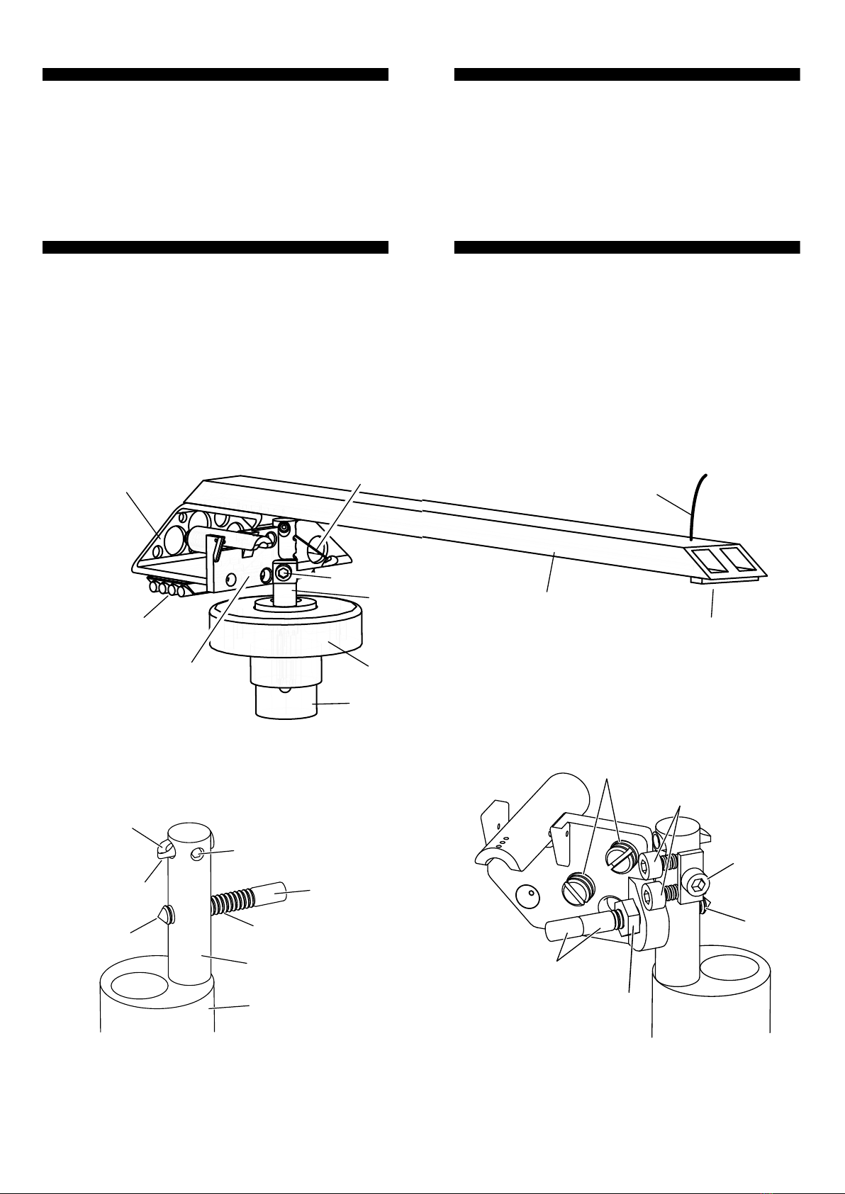
In the rest position the thrust box rests against
three 6mm grub screws in the bias rig. Two of
these have embedded magnets which capture
the thrust box, whereas the uppermost screw
relies on the arm’s downforce for contact, and
sets the rest level of the arm. They can be
advanced or withdrawn with an Allen key to
achieve a stable arm-rest position. Ideally both
rest magnets will make contact with the thrust
box when the arm is resting.
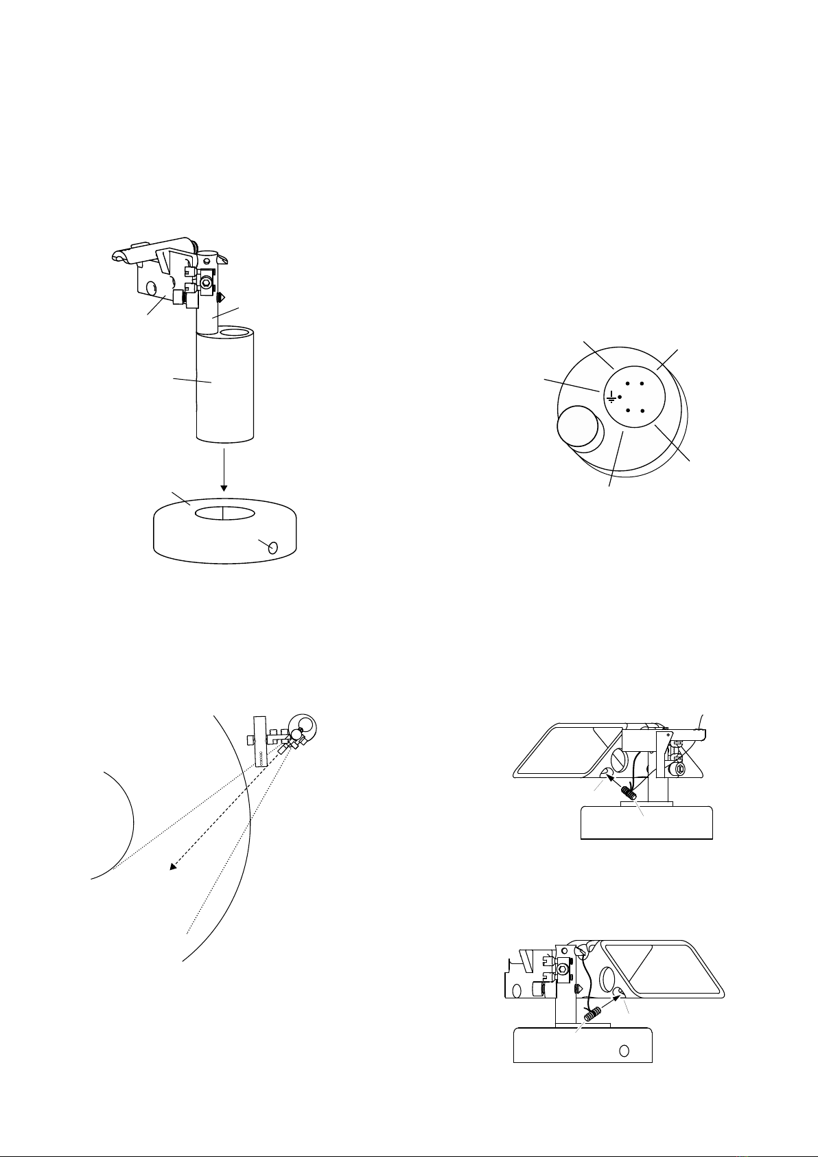
Alignment
A protractor is included to establish optimal
spindle-to-pivot distance, cartridge overhang
and null point alignment.
If it is difficult to set these distances optimally
on your turntable, you can slightly adjust
spindle-to-pivot distance by withdrawing or
extending both the pivot bolt and hoist pipe in
equal measure. If this is done, the pillar will no
longer conserve geometry when it is rotated in
the base, in which case configurations involving
large rotations of the arm pillar will slightly
alter the spindle-to-pivot distance. Please use
your own geometry calculators as the broad
subject of arm geometry optimisation is capable
of lengthy analysis.
12
SET-UP & FINE-TUNING
As with other tone arms, inaccurate
configuration can produce poor results,
whereas precise tuning will enable you to get
the best from your records. Please ensure that
your turntable is level before fine-tuning.
As the suspension settles in, it is worth
regularly checking bias, suspension height, lean
(‘azimuth’) and adjusting the arm’s geometry to
ensure that all are optimal.
Downforce & Inertia
Adjusting the inertia to suit the cartridge
suspension is important. Good results can be
achieved by trial and error, or by calculation.
Set downforce and inertia using the
counterweights which attach magnetically to
the underside of the thrust box, and the mass
adaptor which sits across the arm between the
cartridge and pivot. The further both weights
are from the pivot, the higher will be the arm’s
inertia (‘effective mass’). High compliance
cartridges work better with low inertia, whereas
low compliance cartridges work better with
higher inertia. With long arms and heavy
cartridges it may be necessary to place an
additional counterweight inside the thrust box.
Downforce Scale Use
Place the supplied downforce scale on the
platter. The coin-sized rebates accommodate a
UK penny, a US cent or a Euro centime as the
balancing weight. The dimples represent 1/10
gram increments in the range 1.2g - 4g. Adjust
the counter-weight until the scale balances with
your stylus resting in the dimple corresponding
to your desired downforce.
13

Blackbird’s low pivot means that your stylus
should maintain contact with the record even at
minimum recommended downforce, or lower.
Consistent tracking with low downforce can
reduce wear on records and styluses.
Bias Tuning
Bias ensures that both sides of a stylus have
roughly equal contact pressure even though
they pull the arm at an offset angle. Ensure that
the electric wiring is free and not constraining
arm movement before setting bias.
Bias is supplied by the bias rotor, which pulls a
pulley attached to the left hoist toggle. The force
is adjusted by screwing the bias weight grub
screw into the bias rotor. A heavier grub screw
is also supplied. The difference between the bias
at the start and end of a record can be changed
by shortening or lengthening the bias pulley.
After adjusting this ratio be sure to adjust the
bias weight screw again. Repeat until bias
across the record is roughly appropriate.
Exact bias is dependent on signal strength,
record speed, stylus profile and other factors, so
aim for a level of bias which roughly neutralises
the net sideways playback forces on the stylus.
Recommended ways of judging bias are:
1. looking at the cantilever exactly head-on
while music is playing
2. observing whether the arm moves
centripetally or centrifugally when the
stylus is lowered onto the flat surfaces
between the grooves
14
3. listening for balance across speakers with
passages which are difficult to track or with
a test/set-up record
Suspension Height and
Cartridge Lean
Lean, commonly called ‘azimuth’, is the extent
to which the cartridge leans towards the centre
of the record or away from it. Zero lean is
important for accurate playback and stylus/
record longevity. Lean can be adjusted by
shortening or loosing the left and right hoists
using the hoist spools.
IMPORTANT: when the arm is suspended at
the correct height, the pivot point must make
contact with the thrust box on the straight
line between the two points where the hoists
meet the thrust box.
A straight-edged slip of paper can help to
establish correct pivot height. Insert the paper
between the hoists and the thrust box and raise
the headshell so that the paper’s straight edge
sits on the hoist flex points. Pivot contact should
occur at or just below the paper’s edge.
Once the correct height is set, lean can be
adjusted by shortening and lengthening the two
hoists in equal and opposite measure so that the
15
pivot bolt straight edge
paper
hoists
thrust box

pivot contact remains on the line between the
suspension points. Always check that the pivot
contact lies on this line after adjustments by
resettling the suspension and applying the
paper test again. A period of incremental
adjustments to suspension height may help to
establish optimal performance.
Vertical Tracking Angle
Vertical tracking angle can be set by raising or
lowering the pillar. Take care to support the
pillar while loosing the locking screw as there is
no brake. Slide the pillar up or down and gently
tighten the locking screw. The tightness of the
locking screw can affect the sound, so adjust it
to taste. Tighter is often not better.
16
17
DISASSEMBLY
To disassemble, reverse the installation.
1. Protect your stylus with a guard.
2. Gently lift the arm to raise it and use the
tweezers to feed the left and right hoist
toggles through the hoist holes in the thrust
box, being careful not to tug the electrical
connections destructively.
3. Use the tweezers to unplug the electrical
contacts by gripping the plugs with
tweezers, not the wires, and gently pull
them upwards until they detach.
4. The arm is now detached and can be stored
somewhere safe.
5. Unplug the amplifier cable from the pillar.
6. Loosen the pillar locking bolt, taking care
not to allow the pillar to drop, and remove
the pillar.
7. Unbolt the base.

19
SOLVING PROBLEMS
Inconsistent Lean
When the arm is new, or when adjustments are
made, lean may vary slightly between the start
and end of a record. This will normally pass as
the hoists settle in.
If this persists, it may result from under-
extension of the hoist pipe eye relative to the
pivot point. To extend the hoist pipe, loosen the
hoist pipe locking screw and push the hoist pipe
further out so that its eye is directly above the
pivot point. Do not over-extend the hoist pipe
lest contact at the pivot be lost. After extending
the hoist pipe, you can test that contact is still
maintained at the pivot by tapping the back of
the thrust box towards the pivot. There should
be no play or movement.
Excess Bias
Sometimes it can be difficult to set appropriate
bias. The first step in solving excess bias is to
make sure that the arm’s yaw equilibrium is on
or near the playing surface. Balance the arm
with the counterweight so that it floats above
the record surface or rises slowly. Disable the
bias rotor in the upright position with a match
or piece of paper. Observe the default track
position of the arm. If it is not on or near the
hoist pipe
hoist pipe eye
hoist pipe
lock screw
pivot bolt
pivot point
post
pillar
pivot
magnet
18
MAINTENANCE
Thrust Box Bolts
After long periods check that the bolts which
attach the arm to the thrust box are tight. Do
not overtighten as this could split the carbon-
fibre tubes.
Pivot point
A severely blunted pivot point might
compromise performance. However, it is easy to
replace the pivot bolt with a newly-sharpened
one. A sharpened mild steel M4 bolt suffices,
although a hardened or HSS tip will last longer.
HSS-tipped pivot bolts are available from
SUPATRAC. Stainless steel is not recommended
as it is not paramagnetic.
Hoists
Look for fraying of the hoists at flexion points
like the hoist pipe eye, which can indicate that
they are ready for replacement. They should last
a long time, and if they look to be in sound
condition then there is no need to change them.
When replacing hoists, terminate the ends with
a figure of eight and use the bend of a slip knot
around the hoist toggles, and a boom hitch
around the knotched head-end of the spools.
hoist spool
bunch and tighten
boom hitch

playing band, unhitch the right hoist toggle and
feed it around the left hoist in one direction or
the other, and reinsert the hoist toggle, before
pushing the arm backwards and gently allowing
the bearing to resettle. Repeat feeding the right
hoist around the left in one direction or the
other until the arm’s yaw equilibrium is in or
near the playing band. Once this is achieved,
use the three other methods described in the
installation and tuning chapters to reach
appropriate bias across the record.
Excess bias may also arise from the eye of the
hoist pipe being too near the post as compared
to the pivot, in which case extend the hoist pipe
as described above.
FURTHER INFORMATION
SUPATRAC tone arms are designed and made
by hand in Chelsea, London, England.
For further information, please visit
www.supatrac.com or email info@supatrac.com
© SUPATRAC 2022
20
Table of contents
Other SUPATRAC Turntable manuals