1. WARNING
• Before using or performing maintenance on your Material Lift, please read the manual
thoroughly to familiarize yourself with the proper usage of and maintenance of your product.
• This Material Lift should only be used in a professional and safe manner, Maintenance and
Testing Personnel should only use this equipment when necessary.
• The material lift must be inspected before use, if a material lift is damaged, has malfunction-
ing or missing parts, do not use, contact the manufacturer for replacememt parts.
• Unauthorized modifications to the product in any way are not permitted and can be danger-
ous. Unauthorized modifications will automatically void all product warranty and the manufac-
turer bears no liability to damages or injuries caused by such unauthorized modifications.
• Do not place your legs, feet or other body parts under the lift during using.
• This lift is not designed for the use of transporting or lifting people, pets or livestock of any sort.
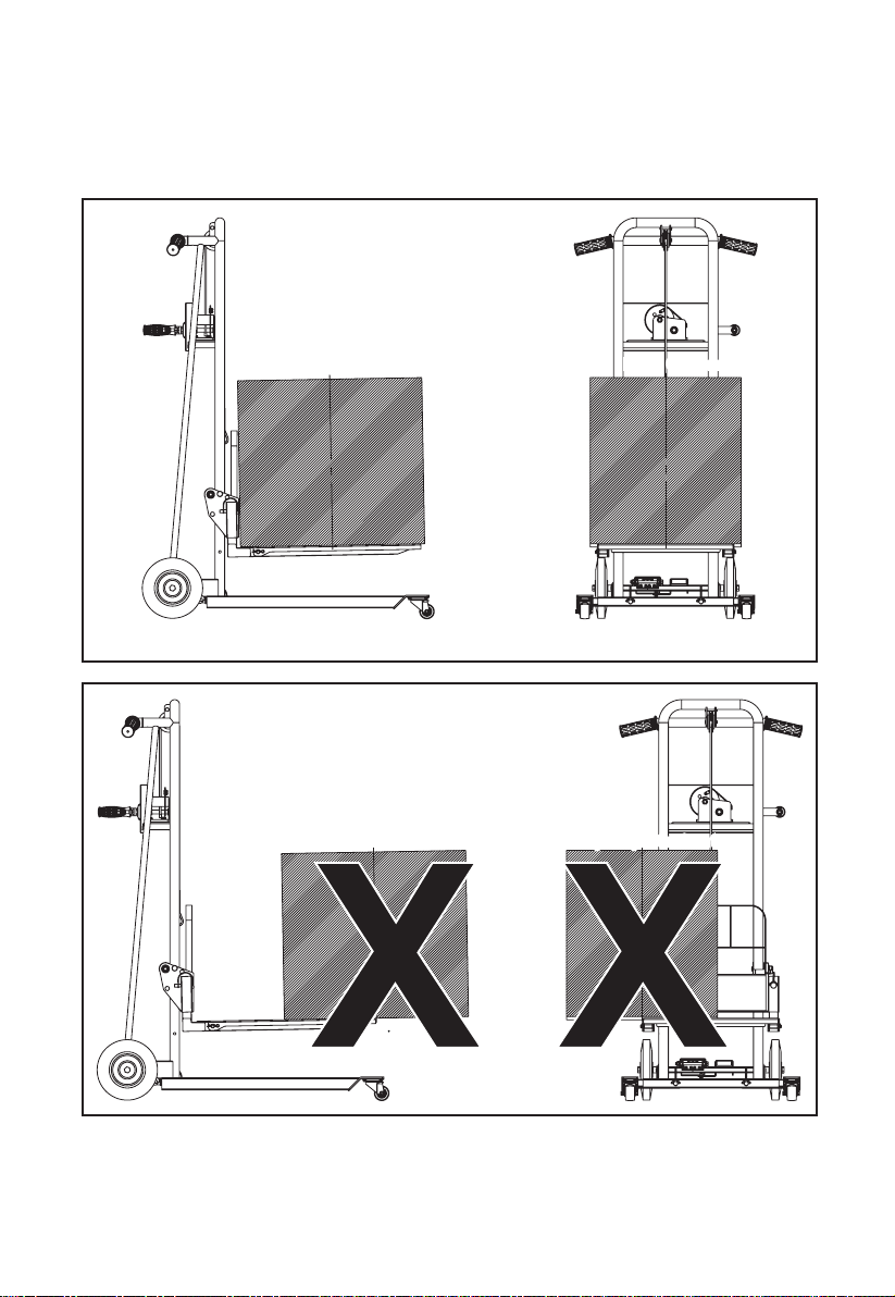
• To avoid the risk of lift overturning when loading, ensure that the center of gravity of the heavy
objects is in the right place on the forks or flatbed (refer to 7.1).
• All heavy objects should be centered properly before lifting or moving the unit.
• Do not turn the winch counterclockwise to lift weight.
• Do not put polyethylene rope close to a fire source or sharp objects,such as blade.
• Do not overload the lift.
• The operator must not leave the lift unattended while in use during the lifting process of the
heavy objects. When walking away from the Lift, operator must lower the height of the heavy
objects.
• Do not remove or obscure the labels on the lift, make sure all labels are clear and easy to
read, otherwise do not use it.
• Do not operate this material lift if you are under 16 years old.
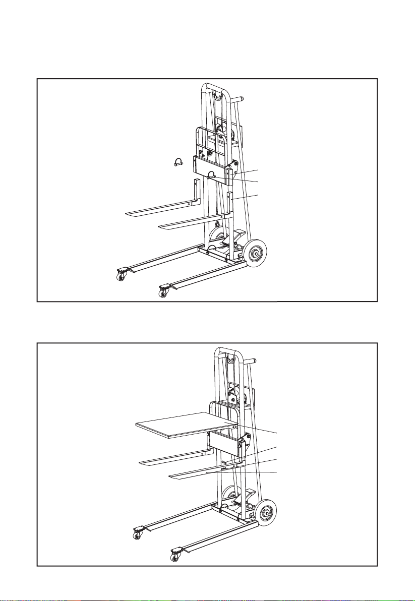
2. MAIN USE
Material lift with compact design and ease of operation. Intended for small and medium-sized
warehouses, processing workshops, home areas handling or loading and unloading heavy
objects, can achieve short distance or small space to move heavy objects and other opera-
tions.
3. TECHNICAL SPECIFICATIONS
• The maximum load capacity of the heavy objects in area
from center to root area is 330Lbs (150Kgs).
• The maximum load capacity of the heavy objects in head
area is 156Lbs (70Kgs).
EN 1
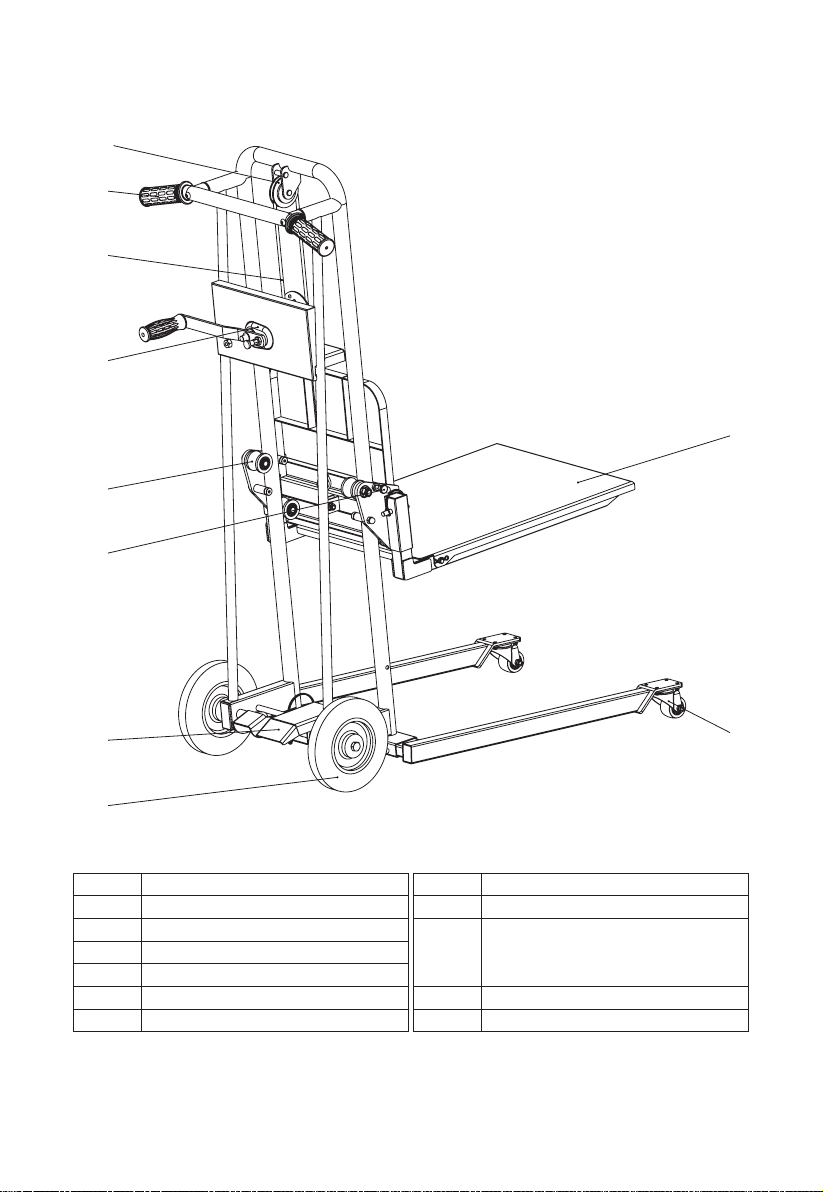
SKU#
Lifting Height
Max. Lifting Weight
Load Mode
Lift Height
Fork Size
Plate Size
Item Size
Net Weight
GUO097
39.37" (1000mm)
330Lbs (150Kgs)
Fork; Flatbed (option)
3.14"~39.37"(80~1000mm)
23.62"x17.71"(600x450mm)
23.42"x17.79"(595x452mm)
38.2"x23.6 "x51.2" (970x600x1300mm)
79Lbs(36Kgs)
Fork Center
Head
Area
Head
Area
Root
Area
Root
Area