© 2023
Step 4 of 5
Order #XXXXX
Locked layer contains
placeholder marks.
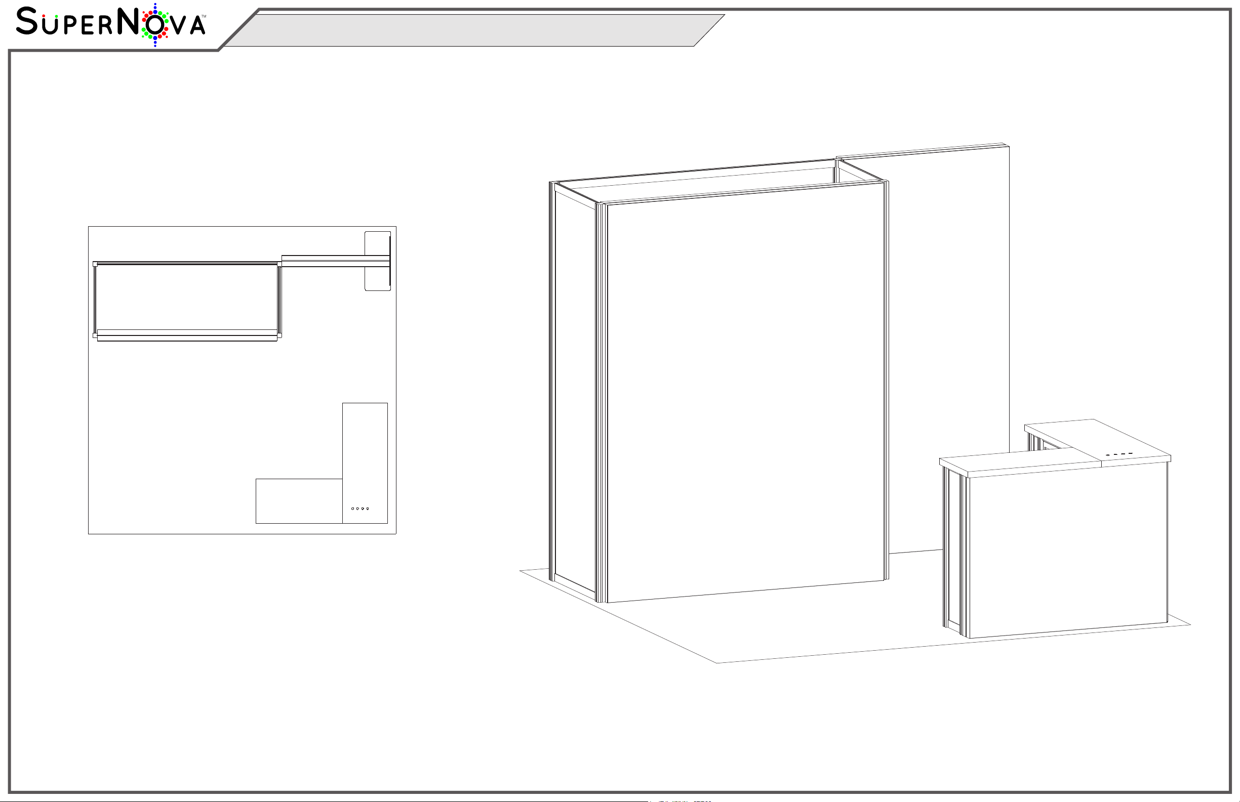
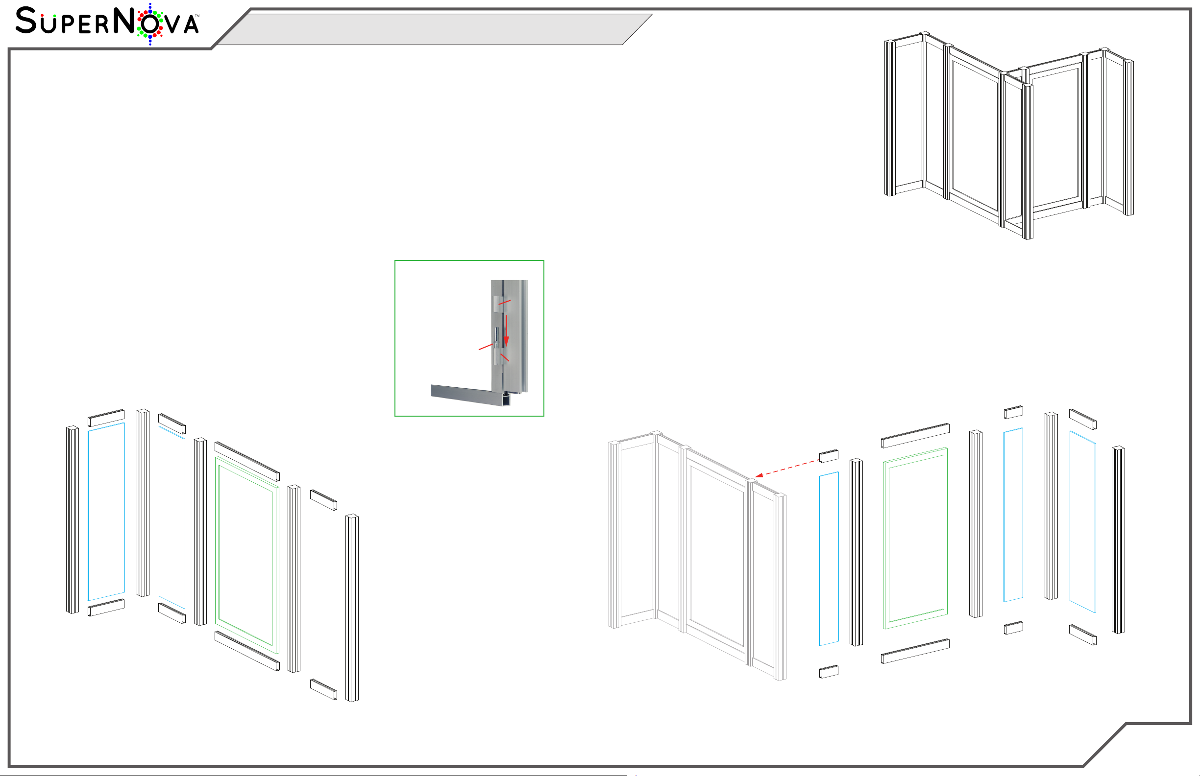
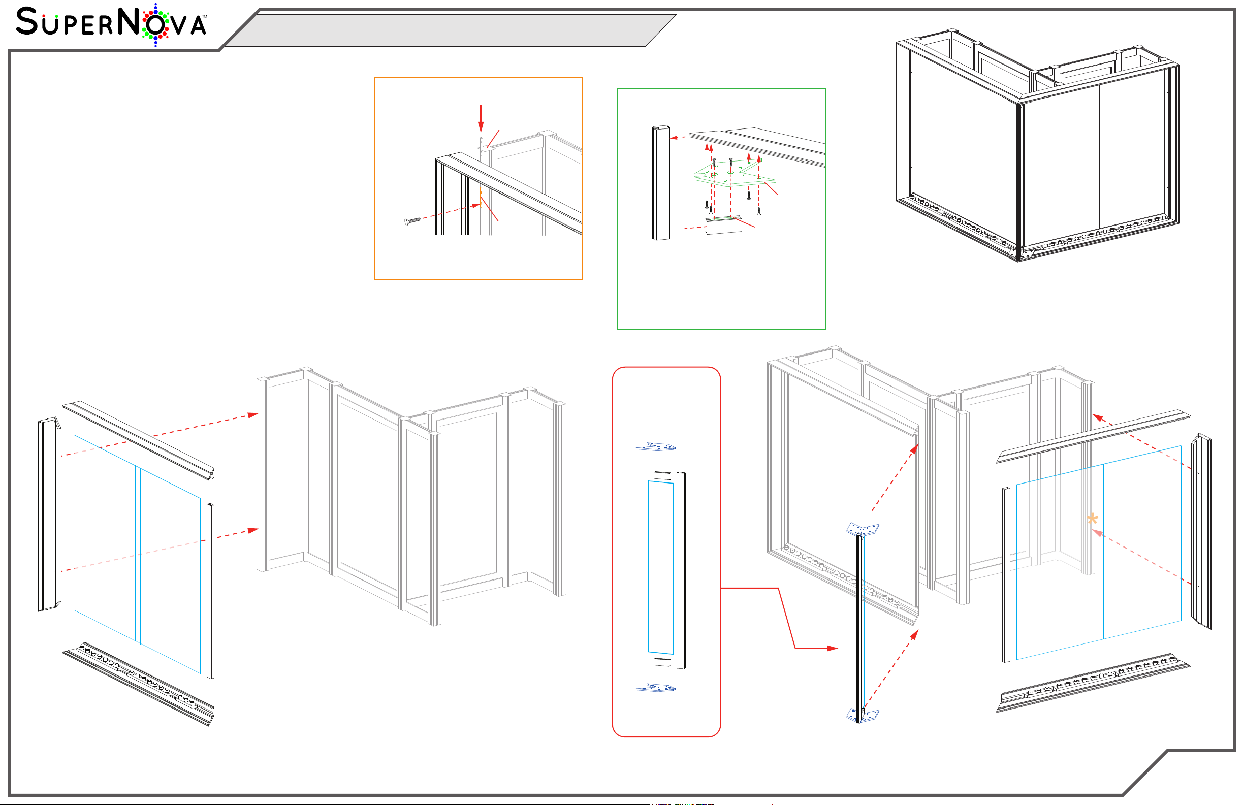
Completed Assembly
Steps:
1) Connect horizontals [23] and [23A] to vertical [22] and
horizontals [25] and [25A] to vertical [24] See CEI110
Frame Assembly sheet for instruction.
2) Attach assembled frames to verticals [1] and [15], as
shown. See Frame to Assembly Attachment detail.
3) Slide 2-part Infills into back of both assembled
CEI110 frames & secure with verticals [11] & [11A].
4) Assemble horizontals [21,21A] & two brackets to vertical [20],
then attach brackets to CEI110 corners [23/25] & [23A/25A],
inserting Infill. See Z45 & Bracket Connection detail.
Item
11,11A
20
21,21A
22
23,23A
24
25,25A
Qty.
1,1
1
1,1
1
1,1
1
1,1
Description
35.853”h Z33 Vertical Extrusion
38.752” TSP2 Vertical Extrusion
3.193” Z31 Horizontal Extrusion
39.5” CEI110 Vertical Extrusion
47.75” CEI110 Horizontal Extrusion
39.5” CEI110 Vertical Extrusion
50.037” CEI110 Horizontal Extrusion
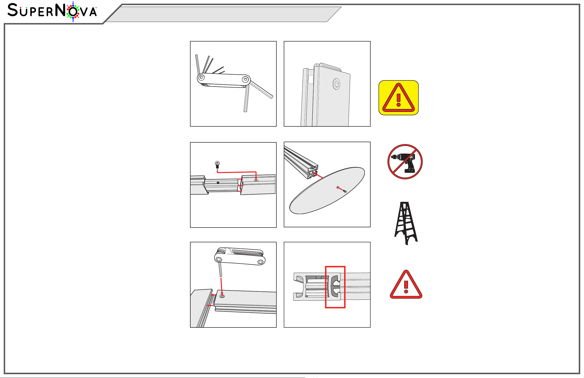
Frame to Assembly Attachment
Bolt
CEI110
S44
Connector
*
Slide Connector into S44 vertical, then
tighten set screws to secure. Attach
CEI110 vertical to Connector, using bolt.
Slide Connector into Z31 horizontal, then
tighten set screws to secure. Attach Z31
to Bracket, using bolts. Attach bracket to
CEI110 horizontal, using bolts. Slide TSP2
vertical into slot of Bracket, then
secure lock of Z31 into vertical TSP2.
Connector
Z31
CEI110
TSP2
Z31 & Bracket Connection
*
Bracket
Corner
Assembly
Infill
23A
23
11
1
22
Infill
Infill
*
*
11A
*
*
20
15
24
25
25A
21
21A
Bracket
Bracket
*
*Infill
Infill
Infill
20
Bracket
Bracket
21
21A
MOD-1702 Counter Assembly (Cont’d)