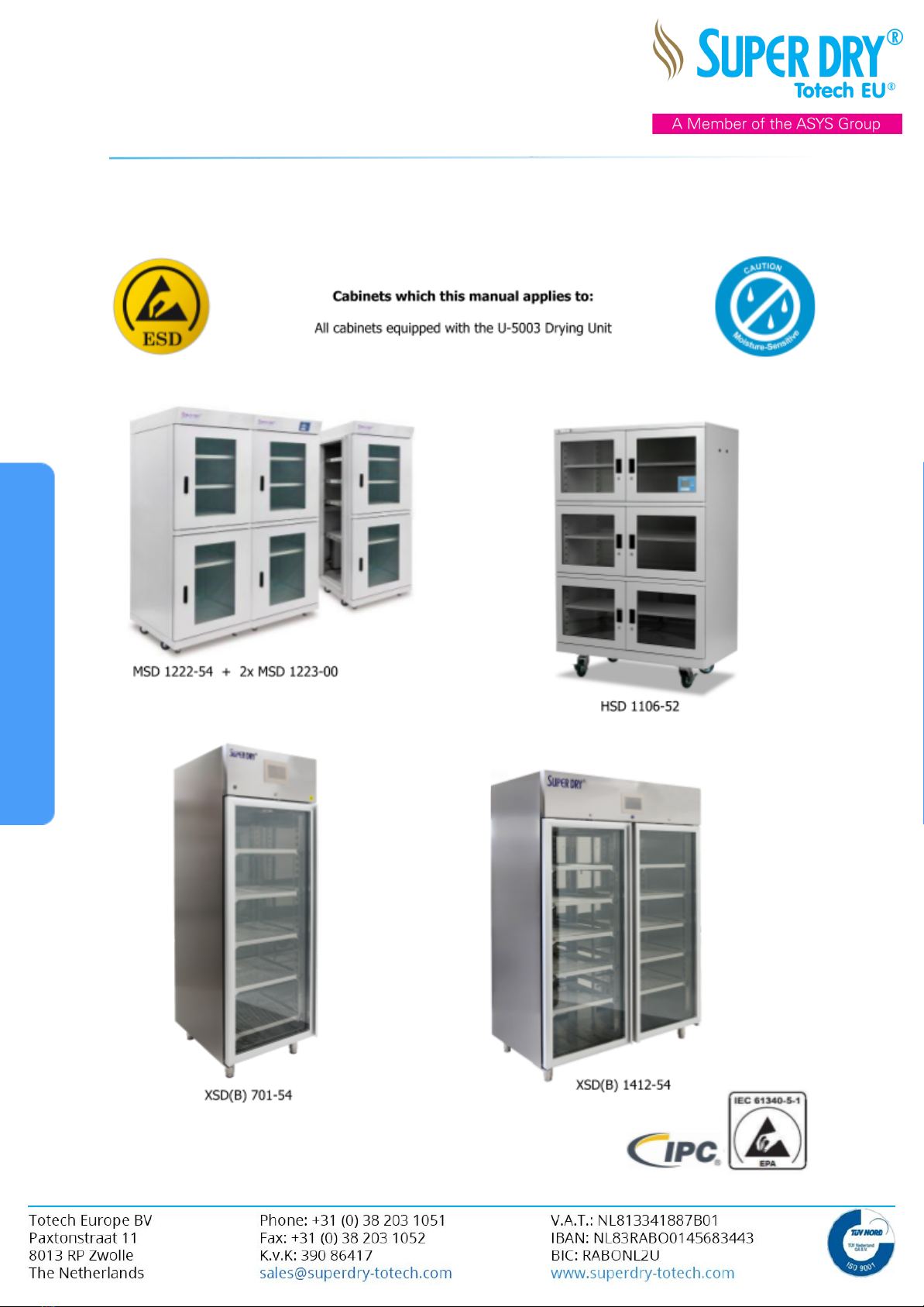
Superdry U-5003 User manual

U-5003 Drying Unit
Operation manual for cabinets with the
U-5003 Drying Unit

U-5003 Drying Unit
Contents
1. Safety Information 4
1.1 Adherence to information provided in the Operation Manual 4
1.2 Operator Obligations 4
1.3 Personnel Obligations 4
1.4 Organizational Measures 4
1.5 Information related safety precautions 4
1.6 Intended use 5
1.7 Hazards related to dryer handling 5
1.8 Protective devices 5
1.9 Electrical hazards 5
1.10 Hazards arising from hot surfaces 5
1.11 Maintenance, Service and troubleshooting 6
1.12 Dehumidifier modification 6
1.13 Dehumidifier cleaning and disposal 6
2. Specification 7
2.1 Use 7
2.2 Operating conditions 7
2.3 Function 7
3. Start-Up 8
3.1 Handling with hoisting gear 8
3.2 Installation 8
3.3 Startup 8
4. Settings 9
4.1 Access to the menu 9
4.2 Language menu + Software version 9
4.3 Humidity set point 9
4.4 Humidity alarm limit 9
4.5 Humidity alarm delay 9
4.6 Set point temperature + heater timer 10
4.7 Temperature alarm deviation 10
4.8 Temperature alarm delay 10
4.9 Door alarm 10
4.10 Interlocking (key-lock display) 10
4.11 Manual regeneration 10
4.12 Changing the standard IP address from the cabinet 11
4.13 Setting the time and date 13
5. Software 13

U-5003 Drying Unit
6. Webserver 14
6.1 Supported Browsers 14
6.2 Supported Devices 14
6.3 Supported language versions of web pages 14
6.4 Log on to the web server 14
6.5 Display LOGO! system information 15
6.6 Using the virtual display on the web server 15
7. Calibration 16
8. Maintenance 16
9. Troubleshooting 17
9.1 For malfunction 17
9.2 Measuring faults 17
9.3 Communication error via Ethernet 17
9.4 Display indicates “BM no resp Press ESC” 17
9.5 No indication on Display 17
9.6 Logic module and extension module checking 17
9.7 Humidity too high 18
9.8 Temperature too low 18
10. Warranty and Liability 19
10.1 Warranty and liability 19
10.2 Full Warranty 19
10.3 Exchange warranty 19
10.4 Third year warranty 20
10.5 Guidelines for the RMA procedure of Totech Europe B.V. 20
11. Serial numbers 21
11.1 Cabinet serial numbers 21
11.2 Dry-unit serial numbers 21
12. CE Declaration 22

U-5003 Drying Unit
1. Safety Information
1.1 Adherence to information provided in the Operation Manual
Being familiar with the basic safety information and regulations is essential for safe handling and
failure-free operation of this dehumidifier.
✓This Operation Manual contains the most important information required in order to safely
operate the dehumidifier.
✓Please ensure, all personnel operating the dehumidifier adheres to this Operation Manual and
in particular to the safety information provided herein.
✓Additionally, any rules and regulations with respect to accident prevention, applicable at the
your respective location, are to be complied with.
1.2 Operator Obligations
The operator undertakes to exclusively authorize individuals to work at the dehumidifier, who:
✓are familiar with relevant regulations on occupational safety and accident prevention, and
have been trained in the dehumidifiers handling;
✓are in possession of and/or have proven to possess the required expertise and know-how;
✓have read and understood the safety information and precautions provided in this Operation
Manual.
✓Furthermore, the operator undertakes to regularly check its personnel's for a safety-conscious
mode of practice.
1.3 Personnel Obligations
All personnel assigned to operate the dehumidifier, undertake to:
✓comply with the relevant occupational safety and accident prevention regulations and follow
the safety information and precautions provided herein, before operating the dehumidifier.
1.4 Organizational Measures
✓Required personal protective equipment (PPE) is to be provided by the operator.
✓All existent safety installations are to be inspected regularly.
1.5 Information related safety precautions
✓Ensure the Operation Manual's general availability at the dehumidifiers application site.
✓In addition to the Operation Manual, also provide for and ensure to comply with general as
well as local regulations on accident prevention and environmental protection.
✓Ensure to keep all safety information and precautions applied to the dehumidifier in legible
condition.

U-5003 Drying Unit
1.6 Intended use
The dehumidifier is exclusively intended to dehumidify atmospheric air. Any deviating or exceeding
deployment is considered unintended use. Totech EU will not assume any liabilities for damage
resulting therefrom.
Dehumidifiers must not be mounted in and/or exposed to the intake of liquids (e.g. filled
tanks or sumps, flooded areas etc.).
Operation in and/or with potentially explosive ambiance is not permissible.
Intended use also includes compliance with all information provided in the Operation Manual as well
as adherence to the remarks made on.
1.7 Hazards related to dryer handling
The dehumidifier was built in accordance with state-of-the-art technology and generally accepted
technical safety requirements. Ensure to exclusively use it:
✓for its intended use;
✓in good order and condition with respect to safety.
✓Ensure to immediately remedy any malfunction, which might impede the dehumidifiers safety.
1.8 Protective devices
✓Generally ensure all protective devices to be properly installed and functional before operating
the dehumidifier.
✓Protective devices may only be removed:
a) After shutdown
b) As safeguarding against unintended restart.
✓For delivery of subcomponents, the operator shall ensure the standard installation of
protective devices.
1.9 Electrical hazards
✓Works performed at the electrical power supply are to be executed by qualified electricians
only.
✓Ensure to always keep the control area locked. Access is to be granted to authorized and
adequately equipped personnel only.
✓In the event works are to be performed at live parts, ensure to provide for a second person
who can switch off electricity, if necessary.
1.10 Hazards arising from hot surfaces
✓During regeneration cycles, the ambient is re-fed with absorbed humidity by heating. This
process may cause the dehumidifiers surface to heat up to approx. 60°C.
✓Ensure not to touch the operating dehumidifier without wearing adequate protective
equipment.
✓Ensure the dehumidifier to be adequately aerated.
✓Ensure to keep a minimum distance of 5 cm at the unit's back side.

U-5003 Drying Unit
1.11 Maintenance, Service and troubleshooting
✓The dehumidifier is maintenance-free.
✓Ensure to inform operators prior to the commencement of maintenance activities.
✓For repair works, switch dehumidifier to neutral and secure main switch against unexpected
restart.
✓Apply restart warning sign.
✓Check unscrewed fastenings for secure tightness.
✓After completion of repair works, check safety devices for functionality.
1.12 Dehumidifier modification
✓Any modification, extension, and/or conversions to the dehumidifier are subject to Totech
EU's written consent.
✓Exclusively use original spare parts to ensure the dehumidifiers proper and safe function and
operation.
1.13 Dehumidifier cleaning and disposal
Ensure proper handling and disposal of deployed substance and materials. This particularly applies to
cleaning activities including the use of solvents.

U-5003 Drying Unit
2. Specification
2.1 Use
Dehumidifiers, which function according to the adsorption principle, are deployed for drying functions
in process engineering, air-conditioning technology, and air-dehumidification in production and
storage spaces, inside which products and installations require particularly low humidity. Drying Unit
U-5003 with integrated humidity control has been specifically designed for being deployed in drying
storage cabinets and drying rooms, in which a particularly low residual moisture content is of specific
importance.
2.2 Operating conditions
In general, dehumidifiers made by Totech are designed for initial conditions of 20-40°C at 0-60%RH.
The process air decreasing relative humidity and/or the regeneration air increasing relative humidity
will adversely affect dehumidification performance.
✓Ensure to exclusively operate the dehumidifier in ambient temperatures (control-side) ranging
between -20°C and +40°C!
✓The process air intake temperature may not exceed a maximum of +60°C; the regeneration
air intake temperature may not drop below the minimum of -15°C!
✓Ensure the intake air does not contain any free water (water drops)!
✓Ensure dehumidifiers are not mounted in and/or exposed to the intake of liquids (e.g. filled
tanks or sumps, flooded areas etc.).
✓Any operation in and/or with potentially explosive ambience is not permissible.
✓In case contaminated air is used for pressure admission, ensure to consider respective
adverse effects on the adsorbent!
2.3 Function
The device has been equipped with a custom-programmable logic module, mounted in the cabinet.
The respective module serves to control the device's humidity, temperature, and functions monitoring.
It provides an external display, indicating several reports such as malfunction, alarms, actual and
pre-set values. Individual data can be retrieved by pressing the control panel's pushbuttons, whereas
fault reports are given highest priority.
In order to ensure ideal dehumidification, the zeolite-filled drying unit requires adequate regeneration.
Therefore the device has a dynamic regeneration cycle. This means when the set point cannot be
reached within a preset time, the dry-unit will start a regeneration cycle automatically. The minimum
time between 2 regeneration cycles is 3 hours to protect the desiccant material inside. Each individual
regeneration cycle will take about 30 minutes. During regeneration processes, active dehumidification
is not feasible.
In order to facilitate the cabinet's tempering an additional circulating air-heater - depending on
respective design models - can be installed.
The air temperature can be controlled by means of the logic module, integrated with the drying unit.
The function is operated via the central text display. The cabinet heater will be deactivated during the
regeneration process and in case of sensor failure.
An alternative option is using an additional heater functioning as a stand-alone unit.
The regeneration process of the dry unit generates heat, which causes a short-term increase in
temperature inside the cabinet. The net increase is dependent on many factors, and a net increase of
5°C is not uncommon.

U-5003 Drying Unit
3. Start-Up
3.1 Handling with hoisting gear
Ensure to lift the device by means of forklifts or with secured harnesses. Do not use pipe connections
or other attachment parts as lifting points.
3.2 Installation
With respect to the device's installation, please adhere to the following:
✓Do not expose the device to weather. Only special weatherproof models are suitable for
outdoor installation.
✓Ensure the intended installation site to be plain and capable of carrying the dehumidifiers
operating weight. The device does not require foundation.
✓Provide for a clearance of at least the device's width (height) for repair and
maintenance/servicing works at the operating side and the inspection lids, in particular at the
rotor.
✓Dehumidifiers may not be mounted in and/or exposed to the intake of liquids, e.g. filled tanks
or sumps, flooded installation sites etc.
✓Operation in and/or with potentially explosive ambience is not permissible.
3.3 Startup
Prior to initial operation, ensure to check all mechanical and electrical connections for secureness
and leak-tightness. Also remove possible soiling.
The drying unit has been designed for a supply voltage of 230 Volts / 50 Hz, and may exclusively be
operated with the respective voltage.
Connect the plug to a safety socket. If the device does not immediately start automatically, it is in
standby mode. In that case, please press the [ON]-button in order to activate the device.
The cabinet's initializer will then start. As soon as initialization has been completed, the main menu
will appear on the display, and the ventilators will start. Following initialization, the program will start
with regeneration of the absorber. The display will indicate "Regeneration". Furthermore, it will
indicate relative humidity and temperature of the cabinet's/room's interior. The (optional) green signal
light will indicate the respective state by means of a blinking green signal. After the regeneration
process completion, the device will switch to drying mode, which is indicated by a continuous
green-colored signal. After regeneration which takes about 20-30 minutes the heater inside the
cabinet will be activated.
The preset temperature will be reached after approximately 4 hours. After the preset value has been
reached the temperature will stay at the preset level.
The cabinet is enabled immediately after start-up; its full drying performance will be achieved after
approx. 24 hours.
In order to switch off the device, please press the [ON]-button during the drying operation, located
on the external display. Keep the pushbutton pressed for 3 seconds. This power-off function will
switch the device to idle mode, and deactivate all control outputs and display functions. However, the
device itself will remain switched on. Consequently, please always disconnect the device from the
mains connection if maintenance/servicing activities are performed. This function is deactivated during
regeneration.

U-5003 Drying Unit
4. Settings
4.1 Access to the menu
Pressing the [SET]-button once will open the setup menu. It allows for defining respective setting by
means of the buttons [+] and [-].
Briefly pressing the [SET]-button again will open the following reference input menus in sequence:
✓Language
✓Humidity setpoint
✓Humidity alarm limit
✓Humidity alarm delay
✓Setpoint temperature (only available with integrated heater)
✓Temperature alarm deviation (only available with integrated heater)
✓Temperature alarm delay (only available with integrated heater)
If neither the buttons [SET] nor [+] [-] are pressed for a period of 20 seconds, the program will
automatically switch back to the standard display.
4.2 Language menu + Software version
This function serves to define your local language. Available are:
1. German
2. English
The lower section of this menu provides information on the current software version.
4.3 Humidity set point
The reference input menu "Humidity" serves to define requested relative humidity in percent, which -
if undercut - will shut down active dehumidification processes. If the nominal value is not achieved
within a period of 15 minutes, the device will automatically initiate a regeneration process.
Setting a value of "0" will activate the drying unit's non-stop operation. This will realize the lowest
possible residual humidity content by maximum energy use.
4.4 Humidity alarm limit
Pressing the [SET]-button again will open the Alarms Menu. It serves to define humidity alarm limit
value, which activates audible - or optionally visible - alarm, if exceeded.
The alarm will activate an acoustic signal, and switch on the signal light's flashing light. Briefly
pressing the [SET]-button will serve to acknowledge the audible alarm. It will then be reactivated for
new alarms. Both, the alarm signal on the display as well as the signal light are automatically deleted
upon correction of respective alarm causes.
4.5 Humidity alarm delay
This display serves to define the humidity alarm delay, which prevents short-term humidity increases
from triggering alarms.

U-5003 Drying Unit
4.6 Set point temperature + heater timer
This menu will be available if the optional heater has been installed. It serves to define the
temperature requested for the cabinet. In case the defined nominal value is below cabinet
temperature / ambient temperature, the heater will not be activated.
4.7 Temperature alarm deviation
Pressing the [SET]-button again will open the menu Temperature Alarm. It serves to define the
deviation (difference) from set nominal values, which will activate audible or - optionally - visible
alarms, if being undercut or exceeded.
The alarm will activate an acoustic signal, and switch on the signal light's flashing light. Briefly
pressing the [SET]-button will serve to acknowledge the audible alarm. It will then be reactivated for
new alarms. Both, the alarm signal on the display as well as the signal light are automatically deleted
upon correction of respective alarm causes.
4.8 Temperature alarm delay
This display serves to define alarm delays for temperature decreases, in order to prevent short-term
temperature decreases or increases from triggering alarms.
Please note that the heater will be deactivated during regeneration processes. This may cause
short-term decreases (max. 20 minutes) in the cabinet's temperature.
4.9 Door alarm
The alarm delay for a door alarm has been preset to 90 seconds, and does not allow for modification.
In the event doors are opened for longer periods, the alarm will activate an acoustic signal, the
display backlight will change to blinking red, and switch on the signal lamp flashing red, if provided.
Briefly pressing the [SET]-button will serve to acknowledge the audible alarm. It will then be
reactivated for new alarms. Both, the alarm signal on the display as well as the signal light are
automatically deleted upon correction of respective alarm causes.
4.10 Interlocking (key-lock display)
Simultaneously pressing the buttons [+] [-] for 5 seconds will cause the indication "Interlocking
Activated" to appear on the display. The control system is now protected from unintended parameter
re-adjusting. Currently set parameters can be viewed but not modified. If you request to modify the
settings, please press the buttons [+] [-] for another 5 seconds, until the display indicates "Unlocked".
All functions can be re-accessed unrestrictedly again.
4.11 Manual regeneration
This function is only available during drying operation. Short press the [ON]-button. Text will appear
on-screen above the 4 buttons, the third button reads REG. Pressing this button will initiate a
regeneration cycle. The required regeneration intensity will be defined automatically.
Note:
During regeneration (displayed with orange background) you have the possibility to prematurely end a
regeneration cycle with the "stop" button. After the cooling time of 3 minutes, the drying unit switches
to the drying mode.

U-5003 Drying Unit
4.12 Changing the standard IP address from the cabinet
The IP setting cannot be used with a local DHCP server, so the IP address need to be set manually
The Standard IP setting is:
BM (base Module) IP address: 10.31.0.xxx
TDE (display) IP address: 10.31.0.xxx
Subnet mask: 255.255.255.0
Gateway: 10.31.0.1
Choose your own IP address:
Before starting with this procedure please determine 2 IP addresses which can be used for the cabinet
in your local network, and write them down below:
BM (base Module) IP address: __________________
TDE (display) IP address: __________________
Subnet mask: __________________
Gateway: __________________
If you do not know which IP address can be used please ask your local IT administrator.

U-5003 Drying Unit
Procedure on how to change the IP address:
For this procedure use only the arrow keys on the right side of the screen
From the standard screen press:
✓Arrow down
✓ESC
✓Arrow down
✓Select Logo settings ⇒ OK
✓Select stop ⇒ OK
If the stop function is not available, please navigate to Setup and press OK. The display will ask you to
login as Admin, enter password “LOGO” to login and press OK. Now you should be able to continue,
select stop and press OK.
✓Arrow left (Select yes) ⇒ OK (BM is stopped)
✓Arrow down (3x) (select Network) ⇒ OK (3x)
✓Select the IP address of your desire with Arrow up/down and Arrow right ⇒ OK
✓Arrow down
✓Select the subnet mask of your desire with Arrow up/down and Arrow right ⇒ OK
✓Arrow down
✓Select the Gateway of your desire with Arrow up/down and Arrow right ⇒ OK
✓ESC (3x)
✓Arrow down (2x) ⇒ OK (TDE settings)
✓Select TDE Network ⇒ OK (2x)
✓Select the IP address of your desire with Arrow up/down and Arrow right ⇒ OK
✓Arrow down
✓Select the subnet mask of your desire with Arrow up/down and Arrow right ⇒ OK
✓Arrow down
✓Select the Gateway of your desire with Arrow up/down and Arrow right ⇒ OK
✓ESC (2x)
✓Arrow up (2x) Logo selection ⇒ (OK)
✓Select the IP address from LOGO with Arrow up/down and Arrow right ⇒ OK
✓ESC
✓Arrow down (Logo! Setting) ⇒ OK
✓Arrow up (3x) ⇒ OK (start)
✓Arrow left (select yes)
✓(BM is running)
✓The display switches automatically to Drying or regeneration

U-5003 Drying Unit
4.13 Setting the time and date
From the standard screen press:
✓Arrow down
Check the current time and date in the display
If it is not ok please follow the next steps:
✓ESC
✓Select LOGO! settings
✓OK
✓Select Setup
✓OK
✓Select Clock
✓Arrow down
✓OK
✓Select set clock
✓OK
✓Change the time (hh:mm) and date (yyyy-mm-dd) with Arrow up/down and Arrow left / right
✓OK
✓ESC (4x)
✓Arrow up
5. Software
This cabinet comes with standard software which can be downloaded from our website at
http://www.superdry-totech.com/
With this software the cabinet’s Humidity (RH %) and Temperature (T °C) can be monitored, and
history log files downloaded from the cabinet via TCP / IP.
In order to have the software working correctly the time and date in the cabinet should be set
correctly, see chapter 4.13

U-5003 Drying Unit
6. Webserver
The SuperDry cabinet has an integrated web server which allows you to operate the drying unit from
a conventional PC or a mobile device via the IP address of the LOGO! Device. With this method you
can access the LOGO! Basic module using an internet-connected device (conventional PC, tablet or
smartphone with web browser function).
Via mouse or touch screen - depending on the device being used - the web server allows you to
quickly and easily operate the virtualized LOGO! Basic module or LOGO! TDE (display)
6.1 Supported Browsers
The LOGO! web server supports the following web browsers:
✓Microsoft Internet Explorer with at least version 8.0
✓Mozilla Firefox with at least Version 11.0
✓Google Chrome with at least version 16.0
✓Apple Safari with at least version 5.0
✓Opera with at least version 12.0
6.2 Supported Devices
The LOGO! web server supports the following communication devices:
✓traditional PC
✓Apple iPhone
✓Apple iPad
✓Smartphones and tablet PCs with Android system with at least version Android 2.0
6.3 Supported language versions of web pages
The LOGO! web server supports the following languages for web pages:
✓German
✓English
✓Italian
✓French
✓Spanish
✓Simplified Chinese
✓Japanese
6.4 Log on to the web server
To log on to the desired LOGO! Basic module, follow these steps:
a) Open your web browser.
b) Enter the IP address of your LOGO! Basic module into the address bar. (see chapter 4.12)
- (EXAMPLE) LAN access (Local Area Network) via: http://192.168.0.27
- (EXAMPLE) Remote access via: http://192.168.0.27:8080
Note: Make sure that TCP port 8080 is selected for remote access.

U-5003 Drying Unit
c) Click or tap the button. The LOGO! web server guides you to the welcome page.
Note:
Use the following credentials to logon to the web interface:
Name: Web User
Password: LOGO
d) If necessary select the drop-down list for the desired language.
e) To log into the web server, click or tap the [Log on] button.
Note:
Remote access to the sign-in process may takes several seconds.
If the login fails, press or tap the refresh button or display in your browser (on a conventional
PC alternatively on the function key "F5") to try again.
6.5 Display LOGO! system information
Once you are logged in, the LOGO! web server shows all system information of your LOGO! Basic
module, e.g. module generation, module type, firmware (FW) version, IP address and module status.
6.6 Using the virtual display on the web server
On the left side of the screen, select LOGO! TD.
The real time readings of Humidity (%rH) and Temperature (T °C) are displayed.
The LOGO! web server also enables the normal operation as can be done on the actual display of the
cabinet.
The function keys (F1 to F4) are always enabled. The current function is displayed on the bottom line
of the text display.

U-5003 Drying Unit
7. Calibration
Totech recommends annual calibration inspection or the system's calibration by sensor replacement,
respectively. For the drying unit's calibration, we recommend the following two options:
1. Replacing the sensor by a factory-calibrated sensor. After detaching the screw-fastened
retaining ring, the plug-in sensor can simply be unplugged. The replacement sensor is
mounted in reverse order. Since all settings have been stored in the sensor, its replacement
will serve to calibrate the dehumidifier overall measuring. Additional measurement equipment
or software is not required.
2. Define deviations by means of a calibrated reference dew point meter (minimum accuracy
±0.2%RH or higher), and calibrate the sensor via the software's calibration function. This
proceeding requires data connection to PC and software (for detailed instructions, please refer
to the Software Manual of the manufacturer).
8. Maintenance
Ensure to generally disconnect the dehumidifier from the electrical power supply before opening or
disassembling the device.
Ensure all motors - in particular ventilators - are at standstill before reaching inside the device!
In case the dehumidifier was in operation, please allow a cooling time of at least 30 minutes before
disassembling the device!
General maintenance; Dehumidifier U-5000 has been designed for maintenance-free long-term
operation. A maintenance schedule does thus not exist.
Sensor replacement and calibration; please proceed as described under item 7.
Repair works are to be performed by qualified Totech service engineers or adequately trained
personnel only. Please contact your local Totech dealer, or Totech EU directly at the service portal
found on the website: http://service.superdry-totech.com/

U-5003 Drying Unit
9. Troubleshooting
9.1 For malfunction
✓Disconnect device from power supply completely, and restart after 10 seconds.
✓Check logic module and extension module as described under item 9.6.
9.2 Measuring faults
✓Unplug the sensor and check plug connector.
✓Check the sensor pins.
9.3 Communication error via Ethernet
✓No communication: Check TCP/IP settings, see item 4.12.
9.4 Display indicates “BM no resp Press ESC”
✓Malfunctioning connection between display and logic module.
Check plug connections of display, drying unit, and logic module.
(For checking, the display can be directly connected to the drying unit with a standard
Ethernet cable).
✓Check logic module as described under item 9.6.
9.5 No indication on Display
✓Check plug connections.
✓Check mains fuse in port, and replace if necessary.
✓Check LED for illumination on power supply unit.
a) No LED illuminated ⇒check input-side power supply unit (230VAC); if present, the
logic module needs to be replaced.
b) Red LED illuminated ⇒disconnect secondary power supply unit. If red color remains,
the power supply unit is to be replaced.
c) If illumination switches to green, identify and remedy cause for short-circuit fault.
✓Disconnect external optional equipment (alarm signal light, heater, N2, …) and re-check
✓Disconnect display and re-check
9.6 Logic module and extension module checking
✓Green LED illuminated ⇒ proper function.
✓Red LED illuminated ⇒software update via Ethernet module required. If the respective state
remains, the logic module is to be replaced.
✓No LED illuminated ⇒check voltage supply (24VDC); if present, the logic module is to be
replaced.

U-5003 Drying Unit
9.7 Humidity too high
✓At first startup, wait at least 24 hours for the cabinet to stabilize.
✓The cabinet is in a regeneration cycle, it is normal the humidity will rise during this procedure.
✓Unplug the cabinet, wait 5 seconds and power up the cabinet. Wait at least 6 hours to check
if the humidity decreases.
✓Check the cabinet for any leakage, check the doors and any open connections to the
environment.
✓Check if the cabinet is fully loaded with wet components, the cabinet needs time to dry these
components.
✓Insufficient air flow ⇒ convections vents covered.
✓Fan failure ⇒ replace drying unit.
9.8 Temperature too low
✓Heating module switched off ⇒ switch on heating module.
✓Heating module power supply interrupted ⇒ check mains connection.
✓Plug connection to drying unit disconnected ⇒ check plug connection.
✓Heater or ventilator failure ⇒ replace defect components.

U-5003 Drying Unit
10. Warranty and Liability
10.1 Warranty and liability
Principally, we apply our "General Terms & Conditions", which the operator has been provided with
upon contract conclusion at the latest. Warranty and liability claims in relation to personal injury and
property damage shall be excluded if the same arise from one or more of the causes below:
✓the dehumidifiers unintended use;
✓the dehumidifiers improper and inappropriate installation, commissioning, operation, and/or
maintenance;
✓operation with defect safety devices or non-functional safety and protective devices;
✓unauthorized modification or unauthorized alteration of the technical design;
✓repair works performed in an inappropriate manner;
✓disaster situations, impact by foreign objects, and events of force majeure.
After purchase we provide warranty on all our new products, unless agreed differently.
10.2 Full Warranty
Valid during the first year after purchase of the new product.
✓All drying cabinets, Vacuum machines & spare parts (including dry-units)
Full warranty:
The end user will receive the defective part replaced at no costs, including transport costs. Totech EU
will collect the defective part after it is replaced with the new one. Actual replacement is done by the
end user with support from Totech technical support if needed.
10.3 Exchange warranty
Valid during the second year after purchase of the new product.
✓All drying cabinets, Vacuum machines & spare parts (including dry-units)
Exchange warranty:
The end user will receive the defective part at a reduced price.
The old part will be returned by the end user to Totech EU as soon as the defective part is replaced
with the new one.
Actual replacement is done by the end user with support from Totech technical support if needed.

U-5003 Drying Unit
10.4 Third year warranty
Valid during the third year after purchase of a new product.
✓Only U-5000 series & U-7000 series
Third year warranty:
Each case will be evaluated by the technical support department, and the part(s) will be provided
under leniency circumstances.
The end user will receive the defective part at an especially quoted price by Totech EU sales
department. The old part will be returned by the end user to Totech EU as soon as the defective part
is replaced with the new one. Actual replacement is done by the end user with support from Totech
technical support if needed.
Please note: all the parts need to be shipped back to Totech Europe B.V. within 30 days of receiving
the warranty parts. If not, you will be invoiced for the normal price.
10.5 Guidelines for the RMA procedure of Totech Europe B.V.
The RMA form:
Requirement: Microsoft Excel, Email.
You can download the RMA from: http://www.superdry-totech.com/
The purpose of this new RMA form is to make one standard form for all Totech dealers & customers.
Please provide us as much as possible details by filling in the yellow lines to speed up the process.
✓Do not change, rename and/or delete any of the worksheets.
✓Please fill in the, Company name, Address, Zip code, City, Country, Tel. nr., Fax. nr., Contact
person, and Email.
✓Fill in ALL the yellow lines of the Complaint form starting with the first one.
✓When the complaint form is filled in correctly the overview sheet will be filled in automatically.
✓Use the “Save as” function in Excel to rename the form. Send the completely filled in
complaint form to our service portal at http://service.superdry-totech.com/
✓Totech Europe B.V. will only accept the Complaint form send in electronically at this stage.
✓We will provide you the warranty and/or repair parts as soon as possible.
Shipping the parts to Totech Europe B.V.
✓Each part must have its own complaint form attached.
✓All parts must be shipped back in original packaging as much as possible, and ESD safe.
✓Those parts that are returned to Totech EU without any proper packaging will not be accepted
for warranty or repair.
✓Broken or damaged parts due to shipping, or bad packaging, will not be accepted for
warranty.
Send all parts to:
Totech Europe B.V.
To: Technical support department
Paxtonstraat 11
8013 RP Zwolle
The Netherlands Europe
Table of contents
Popular Dryer manuals by other brands

Frigidaire
Frigidaire FEQ1442CES0 operating instructions

GE
GE GHDS830EDWS Technical service guide

Bosch
Bosch WTMC6321CN Operating, care and installation instructions

Zanussi
Zanussi ZDC 5370 W Instruction booklet

Kenmore
Kenmore 29" installation instructions

Sloan
Sloan EHD-511 SPOUT installation instructions