Suzuki Baleno User manual

IMPORTANT
WARNING/CAUTION/NOTE
Please read this manual and follow its instructions
carefully. To emphasize special information, the words
WARNING, CAUTION and NOTE have special mean-
ings. Pay special attention to the messages high-
lighted by these signal words.
WARNING:
Indicates a potential hazard that could result
in death or injury.
CAUTION:
Indicates a potential hazard that could result
in vehicle damage.
NOTE:
Indicates special information to make mainte-
nance easier or instructions clearer.
WARNING:
This service manual is intended for autho-
rized SUZUKI dealers and qualified service
mechanics only. Inexperienced mechanics
or mechanics without the proper tools and
equipment may not be able to properly per-
form the services described in this manual.
Improper repair may result in injury to the
mechanic and may render the vehicle un-
safe for the driver and passengers.
WARNING:
For vehicles equipped with Supplemental
Restraint (Air Bag) System:
!Service on or around the air bag system
components must be performed only by
an authorized SUZUKI dealer. Please ob-
serve all WARNINGS, CAUTIONS and
“Service Precautions” under “On-Vehicle
Service” in SECTION 10B before perform-
ing service on or around the air bag sys-
tem components or wiring. Failure to
follow WARNINGS could result in uninten-
tional activation of the system or could
render the system inoperative. Either of
these two conditions may result in severe
injury.
!If the air bag system and another vehicle
system both need repair, SUZUKI recom-
mends that the air bag system be repaired
first, to help avoid unintentional activa-
tion of the air bag system.
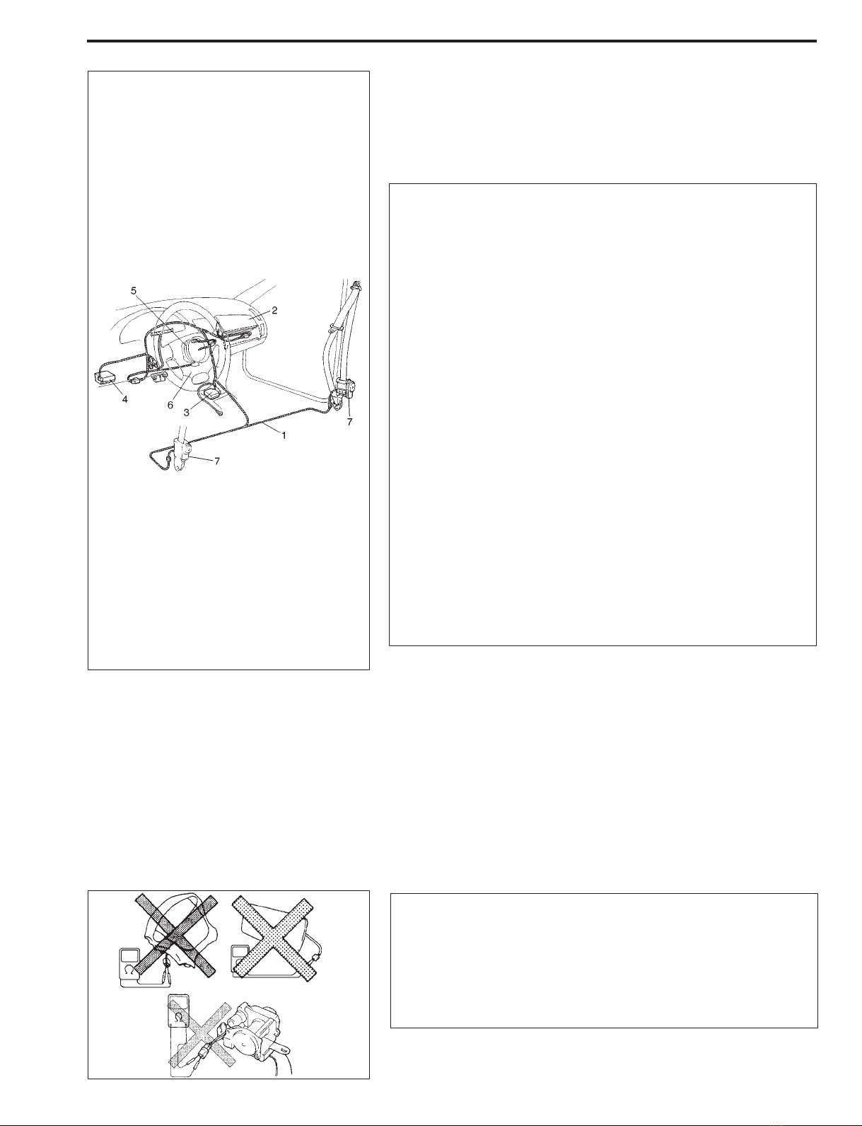
!Do not modify the steering wheel, instru-
ment panel or any other air bag system
component. Modifications can adversely
affect air bag system performance and
lead to injury.
!If the vehicle will be exposed to tempera-
tures over 93!C (200!F) (for example, dur-
ing a paint baking process), remove the
air bag system components (air bag (infla-
tor) modules, SDM and seat belt preten-
sioner (if equipped)) beforehand to avoid
component damage or unintended activa-
tion of the system.

(
x
)(
x
)(
x
)(
x
)
(
x
) (
x
)(
x
)(
x
)
(
x
)
(
x
)
(
x
)
(
x
)
(
x
)
(
x
)
(
x
)(
x
)
(
x
)(
x
)
(
x
)(
x
)
(
x
)(
x
)
(
x
)
(
x
)
(
x
)(
x
)
(
x
)(
x
)
(
x
)
(
x
)
(
x
)
(
x
)
FOREWORD
This manual (Volumes 1 and 2) contains procedures for diagnosis, maintenance, adjustments, minor service op-
erations, replacement of components (Service) and for disassembly and assembly of major components (Unit Re-
pair-Overhaul).
VOLUME 1 contains Chassis, Electrical and Body sections (all sections except engine).
VOLUME 2 contains Engine sections (Section 6 – 6K).
Applicable model: SY413/SY416/SY418 on and after the following VIN NO.
HATCHBACK
GA11S-200001 JSAEGA11S00200001 JSAEGA41S00200001
JSAEGA31S00200001 JSAEGB31S00200001
SEDAN
GC11S-200001 JS2GB31S 15200001 JSAEGC31S15200001
GC31S-200001 JS2GB41S 15200001 JSAEGC41S00200001
JS2GA11S 15200001 JSAEGC11S00200001 JSAEGD31S00200001
JS2GA31S 15200001 JSAEGC31S00200001
JS2GA41S 15200001 JSAEGC31S10200001
WAGON
GC31W-200001 JS2GB31W 15200001 JSAEGC31W10200001
GC41W-200001 JS2GB41W 15200001 JSAEGC31W15200001
JS2GA31W 15200001 JSAEGC11W00200001 JSAEGC41W00200001
JS2GA41W 15200001 JSAEGC31W00200001 JSAEGD31W00200001
The contents are classified into sections each of which is given a section number as indicated in the Table of Con-
tents on next page. And on the first page of each individual section is an index of that section.
This manual should be kept in a handy place for ready reference of the service work.
Strict observance of the so specified items will enable one to obtain the full performance of the vehicle.
When replacing parts or servicing by disassembling, it is recommended to use SUZUKI genuine parts, tools and
service materials (lubricant, sealants, etc.) as specified in each description.
All information, illustrations and specifications contained in this literature are based on the latest product informa-
tion available at the time of publication approval. And used as the main subject of description is the vehicle of stan-
dard specifications among others.
Therefore, note that illustrations may differ from the vehicle being actually serviced.
The right is reserved to make changes at any time without notice.
RELATED MANUAL
!SY413/SY416/SY418 Wiring Diagram Manual
(99512-60G60-015)
OVERSEAS SERVICE DEPARTMENT
"COPYRIGHT SUZUKI MOTOR CORPORATION 2000

7A
7A1
7A2
7B
7B1
7C
7C1
7F
8
8A
8G
9
9J
6
0A
6-1
6-2
6A1
6A3
6B
6C
6E1
6E2
6E3
6E4
6F1
6F2
6G2
6G3
6H
6K
0B
1A
1B
3
3A
3B
3B1
3C
3C1
3D
3E
3E1
3F
3G
4
4A
4B
4C
5
5B
6G1
NOTE:
The screen toned Sections 6 – 6K are included in Volume 2 of 2 and Section 8A is in Wiring Diagram Manual.
SECTIONTABLE OF CONTENTS
GENERAL INFORMATION
General Information
Maintenance and Lubrication
HEATING AND VENTILATION
Heater and Ventilation
Air Conditioning (Optional)
STEERING, SUSPENSION,
WHEELS AND TIRES
Steering, Suspension,
Wheels and Tires
Front End Alignment
Manual Rack and Pinion
Power Steering (P/S) System
(Hydraulic Type)
Steering Wheel and Column
(Without Air Bag)
Air Bag Steering and Column
Front Suspension
Rear Suspension (2WD)
Rear Suspension (4WD)
Wheels and Tires
Suspension Control System
DRIVE SHAFT
Front Drive Shaft (DOJ Type)
Front Drive Shaft
(Tripod Joint Type)
Propeller Shafts
Rear Drive Shaft
BRAKE SYSTEM
Brakes
Antilock Brake System (ABS)
0A
1A
0B
3
3A
3C
3D
3F
4A
1B
3B
3E
5
3B1
3C1
3E1
3G
4
4B
4C
5B
TABLE OF CONTENTS
ENGINE
Engine (G13/G16 Engine without
WU-TWC)
Engine General Information and
Diagnosis
(G13/G16 Engine with WU-TWC)
Engine General Information and
Diagnosis
(J18 Engine with WU-TWC)
Engine Mechanical
(G13 and G16 Type Engine)
Engine Mechanical
(J18 Type Engine)
Engine Cooling
Engine Fuel
Electronic Fuel Injection System
(G13/G16 Engine without
WU-TWC)
Engine and Emission Control
System
(G13/G16 Engine with WU-TWC)
Electronic Fuel Injection System
(J18 Engine without WU-TWC)
Engine and Emission Control Sys-
tem (J18 Engine with WU-TWC)
Ignition System (G13/G16 Engine)
Ignition System (J18 Engine)
Cranking System
(0.8 kW Reduction Type)
Cranking System
(0.8 kW Conventional Type)
Cranking System
(0.9/1.2/1.4 kW Reduction Type)
Charging System
Exhaust System
TRANSMISSION AND CLUTCH
Manual Transmission
(G13 and G16 Engine Models)
Manual Transmission
(J18 Engine Model)
Manual Transmission (4WD)
Automatic Transmission (3 A/T)
Automatic Transmission (4 A/T)
Clutch (Cable Type)
Clutch (Hydraulic Type)
Rear Differential
BODY ELECTRICAL SYSTEM
WIRING DIAGRAM
IMMOBILIZER CONTROL SYSTEM
BODY SERVICE
AIR BAG SYSTEM
8A
SECTION
6
6B
6A1
6G1
7B
7C
8
6C
6K
6E1
6F1
6H
8G
7A
6-1
6-2
6A3
6E2
6E3
9
7F
7C1
7B1
7A1
7A2
6G2
6F2
6E4
6G3
9J

0A
GENERAL INFORMATION 0A-1
SY413/
416/
418
SECTION 0A
GENERAL INFORMATION
CONTENTS
HOW TO USE THIS MANUAL 0A- 2. . . . . . . . . . . . . .
PRECAUTIONS 0A- 3. . . . . . . . . . . . . . . . . . . . . . . . . .
Precaution for Vehicle Equipped with a
Supplemental Restraint (Air Bag) System 0A- 3.
General Precautions 0A- 7. . . . . . . . . . . . . . . . . . . .
Precaution for Catalytic Converter 0A-10. . . . . . . . .
Precautions for Electrical Circuit Service 0A-10. . .
Precaution for Installing Mobile
Communication Equipment 0A-13. . . . . . . . . . . . . .
Precaution in Servicing Full Time 4WD
Vehicle 0A-14. . . . . . . . . . . . . . . . . . . . . . . . . . . . . . .
Intermittent and Poor Connection 0A-15. . . . . . . . .
IDENTIFICATION INFORMATION 0A-16. . . . . . . . . . .
Vehicle Identification Number 0A-16. . . . . . . . . . . . .
Identification Whether Vehicle Equipped
With WU-TWC or Not 0A-16. . . . . . . . . . . . . . . . . .
Engine Identification Number 0A-16. . . . . . . . . . . . .
Transmission Identification Number 0A-16. . . . . . .
WARNING, CAUTION AND INFORMATION
LABELS 0A-17. . . . . . . . . . . . . . . . . . . . . . . . . . . . . . . . .
VEHICLE LIFTING POINTS 0A-18. . . . . . . . . . . . . . . .
ABBREVIATIONS AND SYMBOLS MAY BE
USED IN THIS MANUAL 0A-20. . . . . . . . . . . . . . . . . . .
FASTENER INFORMATION 0A-23. . . . . . . . . . . . . . . .
Metric Fasteners 0A-23. . . . . . . . . . . . . . . . . . . . . . . .
Fastener Strength Identification 0A-23. . . . . . . . . . .
Standard Tightening Torque 0A-24. . . . . . . . . . . . . .

HOW TO USE THIS MANUAL
1) There is a TABLE OF CONTENTS FOR THE WHOLE MANUAL
on the first page of this manual, whereby you can easily find the
section that offers the information you need. Also, there is a
TABLE OF CONTENTS on the first page of EACH SECTION,
where the main items in that section are listed.
2) Each section of this manual has its own pagination. It is indi-
cated at the top of each page along with the Section name.
3) The SPECIAL TOOL usage and TIGHTENING TORQUE
SPECIFICATION are given as shown in figure below.
6) Install oil pump. Refer to Item “Oil pump” for installation of
oil pump.
7) Install flywheel (M/T vehicle) or drive plate (A/T vehicle).
Using special tool, lock flywheel or drive plate, and tighten
flywheel or drive plate bolts to specification.
Special Tool
(A): 09924-17810
Tightening Torque
(c): 78 N·m (7.8 kg-m, 56.5 lb-ft)
1. Flywheel bolts or drive plate bolts for A/T vehicle
4) A number of abbreviations and symbols are used in the text.
For their full explanations, refer to “ABBREVIATIONS AND
SYMBOLS MAY BE USED IN THIS MANUAL” of this section.
5) The SI, metric and foot-pound systems are used as units in this
manual.
6) DIAGNOSIS and CORRECTION are included in each section
as necessary.
7) At the end of each section, there are descriptions of SPECIAL
TOOLS, REQUIRED SERVICE MATERIALS and TIGHT-
ENING TORQUE SPECIFICATIONS that should be used for
the servicing work described in that section.
0A-2 GENGERAL INFORMATION
SY413/
416/
418

PRECAUTIONS
PRECAUTION FOR VEHICLES EQUIPPED
WITH A SUPPLEMENTAL RESTRAINT (AIR
BAG) SYSTEM
1. Air bag wire harness
2. Passenger air bag (inflator) module (if equipped)
3. SDM
4. J/B
5. Contact coil
6. Driver air bag (inflator) module
7. Seat belt pretensioner (if equipped)
WARNING:
!The configuration of air bag system parts are as
shown in the figure. When it is necessary to service
(remove, reinstall and inspect) these parts, be sure to
follow procedures described in SECTION 9J. Failure to
follow proper procedures could result in possible air
bag system activation, personal injury, damage to
parts or air bag system being unable to activate when
necessary.
!If the air bag system and another vehicle system both
need repair, Suzuki recommends that the air bag sys-
tem be repaired first, to help avoid unintended air bag
system activation.
!Do not modify the steering wheel, dashboard, or any
other air bag system components. Modifications can
adversely affect air bag system performance and lead
to injury.
!If the vehicle will be exposed to temperature over 93!C
(200!F) (for example, during a paint baking process),
remove the air bag system components beforehand to
avoid component damage or unintended air bag sys-
tem activation.
DIAGNOSIS
!When troubleshooting air bag system, be sure to follow “DIAG-
NOSIS” in SECTION 9J. Bypassing these procedures may re-
sult in extended diagnostic time, incorrect diagnosis, and
incorrect parts replacement.
!Never use electrical test equipment other than that specified in
this manual.
WARNING:
Never attempt to measure the resistance of the air bag
(inflator) modules (driver and passenger) and seat belt
pretensioners (driver an passenger). It is very dangerous
as the electric current from the tester may deploy the air
bag or activate the pretensioner.
GENERAL INFORMATION 0A-3
SY413/
416/
418

SERVICING AND HANDLING
ALWAYS CARRY AIR BAG (INFLATOR) MODULE WITH
TRIM COVER (AIR BAG OPENING) AWAY FROM BO-
DY.
1. Slit on workbench
2. Workbench vise
3. Lower mounting bracket
ALWAYS PLACE AIR BAG (INFLATOR) MODULE ON
WORKBENCH WITH TRIM COVER (AIR BAG OPEN-
ING) UP, AWAY FROM LOOSE OBJECTS.
WARNING:
Many of service procedures require disconnection of
“AIR BAG” fuse and all air bag (inflator) module(s) from
initiator circuit to avoid an accidental deployment.
Driver and Passenger Air Bag (Inflator) Modules
!For handling and storage of a live air bag (inflator)
module, select a place where the ambient temperature
below 65!C (150!F), without high humidity and away
from electric noise.
!When carrying a live air bag (inflator) module, make
sure the bag opening is pointed away from you. In case
of an accidental deployment, the bag will then deploy
with minimal chance of injury. Never carry the air bag
(inflator) module by the wires or connector on the un-
derside of the module. When placing a live air bag (in-
flator) module on a bench or other surface, always face
the bag up, away from the surface. As the live passen-
ger air bag (inflator) module must be placed with its
bag (trim cover) facing up, place it on the workbench
with a slit or use the workbench vise to hold it securely
at its lower mounting bracket. This is necessary so
that a free space is provided to allow the air bag to ex-
pand in the unlikely event of accidental deployment.
Otherwise, personal injury may result.
!Never dispose of live (undeployed) air bag (inflator)
modules (driver and passenger). If disposal is neces-
sary, be sure to deploy them according to deployment
procedures described in SECTION 9J before disposal.
!The air bag (inflator) module immediately after deploy-
ment is very hot. Wait for at least half an hour to cool
it off before proceeding the work.
!After an air bag (inflator) module has been deployed,
the surface of the air bag may contain a powdery resi-
due. This powder consists primarily of cornstarch
(used to lubricate the bag as it inflates) and by-prod-
ucts of the chemical reaction. As with many service
procedures, gloves and safety glasses should be
worn.
0A-4 GENGERAL INFORMATION
SY413/
416/
418

WARNING:
SDM
!During service procedures, be very careful when han-
dling a Sensing and Diagnostic Module (SDM). Never
strike or jar the SDM.
!Never power up the air bag system when the SDM is
not rigidly attached to the vehicle. All SDM and mount-
ing bracket fasteners must be carefully torqued and
the arrow must be pointing toward the front of the ve-
hicle to ensure proper operation of the air bag system.
The SDM could be activated when powered while not
rigidly attached to the vehicle which could cause de-
ployment and result in personal injury.
ALWAYS PLACE SEAT BELT PRETENSIONER ON
WORKBENCH WITH ITS WARNING LABEL ATTACHED
SIDE FACING UP, AWAY FROM LOOSE OBJECTS.
1. Warning label
WARNING:
Driver and Passenger Seat Belt Pretensioners
!For handling and storage of a live seat belt pretension-
er, select a place where the ambient temperature be-
low 65!C (150!F), without high humidity and away from
electric noise.
!Never carry the seat belt pretensioner by the wires or
connector on the underside of the pretensioner. When
placing a live seat belt pretensioner on a bench or oth-
er surface, always face its warning label attached side
up, away from the surface. As the live must be placed
with its warning label attached side facing up, place it
on the workbench. Otherwise, personal injury may re-
sult.
!Never dispose of live (inactivated) seat belt preten-
sioners (driver and passenger). If disposal is neces-
sary, be sure to activate them according to activation
procedures described in SECTION 9J before disposal.
!The seat belt pretensioner immediately after activation
is very hot. Wait for at least half an hour to cool it off
before proceeding the work.
!With many service procedures, gloves and safety
glasses should be worn to prevent any possible irrita-
tion of the skin or eyes.
GENERAL INFORMATION 0A-5
SY413/
416/
418

CAUTION:
!Even when the accident was light enough not to cause
air bags to activate, be sure to inspect system parts
and other related parts according to instructions un-
der “Repair and Inspection Required after an Acci-
dent” in SECTION 9J.
!When servicing parts other than air bag system, if
shocks may be applied to air bag system component
parts, remove those parts beforehand.
!When handling the air bag (inflator) modules (driver
and passenger), seat belt pretensioners (driver and
passenger) or SDM, be careful not to drop it or apply
an impact to it. If an excessive impact was applied
(e.g., dropped from a height of 91.4 cm (3 feet) or
more), never attempt disassembly or repair but re-
place it with a new one.
!When grease, cleaning agent, oil, water, etc. has got
onto air bag (inflator) modules (driver and passenger)
or seat belt pretensioners (drive and passenger), wipe
off immediately with a dry cloth.
!Air bag wire harness can be identified easily as it is
covered with a yellow protection tube. Be very careful
when handling it.
!When an open in air bag wire harness, damaged wire
harness, connector or terminal is found, replace wire
harness, connectors and terminals as an assembly.
!Do not apply power to the air bag system unless all
components are connected or a diagnostic chart re-
quests it, as this will set a diagnostic trouble code.
!Never use air bag system component parts from
another vehicle.
!When using electric welding, be sure to temporarily
disable air bag system referring to “Disabling Air Bag
System” described in “Precaution” in SECTION 9J.
!Never expose air bag system components parts di-
rectly to hot air (drying or baking the vehicle after
painting) or flames.
!WARNING/CAUTION labels are attached on each part
of air bag system components. Be sure to follow the
instructions.
!After vehicle is completely repaired, perform “Air Bag
Diagnostic System Check” described in “Diagnosis”
in SECTION 9J.
0A-6 GENGERAL INFORMATION
SY413/
416/
418

GENERAL PRECAUTIONS
The WARNING and CAUTION below describe some general precautions that you should observe when servicing
a vehicle. These general precautions apply to many of the service procedures described in this manual, and they
will not necessarily be repeated with each procedure to which they apply.
WARNING:
!Whenever raising a vehicle for service, be sure to follow the instructions under “VEHICLE LIFTING
POINTS” on SECTION 0A.
!When it is necessary to do service work with the engine running, make sure that the parking brake
is set fully and the transmission is in Neutral (for manual transmission vehicles) or Park (for auto-
matic transmission vehicles). Keep hands, hair, clothing, tools, etc. away from the fan and belts
when the engine is running.
!When it is necessary to run the engine indoors, make sure that the exhaust gas is forced outdoors.
!Do not perform service work in areas where combustible materials can come in contact with a hot
exhaust system. When working with toxic or flammable materials (such as gasoline and refriger-
ant), make sure that the area you work in is well-ventilated.
!To avoid getting burned, keep away from hot metal parts such as the radiator, exhaust manifold,
tailpipe, muffler, etc.
!New and used engine oil can be hazardous. Children and pets may be harmed by swallowing new
or used oil. Keep new and used oil and used engine oil filters away from children and pets. Continu-
ous contact with used engine oil has been found to cause [skin] cancer in laboratory animals, brief
contact with used oil may irritate skin. To minimize your exposure to used engine oil, wear a long-
sleeve shirt and moisture-proof gloves (such as dishwashing gloves) when changing engine oil.
If engine oil contacts your skin, wash thoroughly with soap and water. Launder any clothing or rags
if wet with oil, recycle or properly dispose of used oil and filters.
!Make sure the bonnet is fully closed and latched before driving. If it is not, it can fly up unexpected-
ly during driving, obstructing your view and resulting in an accident.
CAUTION:
!Before starting any service work, cover fenders, seats and
any other parts that are likely to get scratched or stained
during servicing. Also, be aware that what you wear (e.g,
buttons) may cause damage to the vehicle’s finish.
!When performing service to electrical parts that does not
require use of battery power, disconnect the negative cable
of the battery.
GENERAL INFORMATION 0A-7
SY413/
416/
418

!When removing the battery, be sure to disconnect the nega-
tive cable first and then the positive cable. When reconnect-
ing the battery, connect the positive cable first and then the
negative cable, and replace the terminal cover.
!When removing parts that are to be reused, be sure to keep
them arranged in an orderly manner so that they may be re-
installed in the proper order and position.
!Whenever you use oil seals, gaskets, packing, O-rings,
locking washers, split pins, self-locking nuts, and certain
other parts as specified, be sure to use new ones. Also, be-
fore installing new gaskets, packing, etc., be sure to remove
any residual material form the mating surfaces.
!Make sure that all parts used in reassembly are perfectly
clean.
!When use of a certain type of lubricant, bond or sealant is
specified, be sure to use the specified type.
“A”: Sealant 99000-31150
!Be sure to use special tools when instructed.
Special Tool
(A): 09917-98221
(B): 09916-58210
0A-8 GENGERAL INFORMATION
SY413/
416/
418

!When disconnecting vacuum hoses, attach a tag describ-
ing the correct installation positions so that the hoses can
be reinstalled correctly.
!After servicing fuel, oil, coolant, vacuum, exhaust or brake
systems, check all lines related to the system for leaks.
!For vehicles equipped with fuel injection systems, never
disconnect the fuel line between the fuel pump and injector
without first releasing the fuel pressure, or fuel can be
sprayed out under pressure.
!Always be careful not to handle electrical parts (computer,
relay, etc.) in a rough manner or drop them.
!When performing a work that produces a heat exceeding
80"C in the vicinity of the electrical parts, remove the heat
sensitive electrical part(s) beforehand.
GENERAL INFORMATION 0A-9
SY413/
416/
418

!Use care not to expose connectors and electrical parts to
water which will be a cause of a trouble.
PRECAUTION FOR CATALYTIC CONVERTER
For vehicles equipped with a catalytic converter, use only un-
leaded gasoline and be careful not to let a large amount of un-
burned gasoline enter the converter or it can be damaged.
– Conduct a spark jump test only when necessary, make it as
short as possible, and do not open the throttle.
– Conduct engine compression checks within the shortest
possible time.
– Avoid situations which can result in engine misfire (e.g.
starting the engine when the fuel tank is nearly empty).
PRECAUTIONS FOR ELECTRICAL CIRCUIT
SERVICE
!When replacing a fuse, make sure to use a fuse of the speci-
fied capacity. Use of a fuse with a larger capacity will cause
a damage to the electrical parts and a fire.
!When disconnecting and connecting coupler, make sure to
turn ignition switch OFF, or electronic parts may get dam-
aged.
!When disconnecting connectors, never pull the wiring har-
nesses. Unlock the connector lock first and then pull them
apart by holding connectors themselves.
0A-10 GENGERAL INFORMATION
SY413/
416/
418

!When connecting connectors, also hold connectors and
put them together until they lock securely (a click is heard).
!Be careful not to touch the electrical terminals of parts
which use microcomputers (e.g. electronic control unit like
as ECM, TCM, ABS control module, SDM etc). The static
electricity from your body can damage these parts.
!Never connect any tester (voltmeter, ohmmeter, or whatev-
er) to electronic control unit when its coupler is discon-
nected. Attempt to do it may cause damage to it.
!Never connect an ohmmeter to electronic control unit with
its coupler connected to it. Attempt to do it may cause dam-
age to electronic control unit and sensors.
!Be sure to use a specified voltmeter/ohmmeter. Otherwise,
accurate measurements may not be obtained or personal
injury may result. If not specified, use a voltmeter with high-
impedance (M !/V minimum) or a digital type voltmeter.
!When taking measurements at electrical connectors using
a tester probe, be sure to insert the probe from the wire har-
ness side (backside) of the connector.
1. Coupler
2. Probe
!When connecting meter probe from terminal side of coupler
because it can’t be connected from harness side, use extra
care not to bend male terminal of coupler of force its female
terminal open for connection.
In case of such coupler as shown connect probe as shown
to avoid opening female terminal.
Never connect probe where male terminal is supposed to
fit.
1. Coupler
2. Probe
3. Where male
terminal fits
GENERAL INFORMATION 0A-11
SY413/
416/
418

!When checking connection of terminals, check its male half
for bend and female half for excessive opening and both for
locking (looseness), corrosion, dust, etc.
!Before measuring voltage at each terminal, check to make
sure that battery voltage is 11V or higher. Such terminal
voltage check at low battery voltage will lead to erroneous
diagnosis.
!When installing the wiring harness, fix it with clamps so that
no slack is left.
!When installing vehicle parts, be careful so that the wiring
harness is not interfered with or caught by any other part.
!To avoid damage to the harness, protect its part which may
contact against a part forming a sharp angle by winding
tape or the like around it.
0A-12 GENGERAL INFORMATION
SY413/
416/
418

PRECAUTION FOR INSTALLING MOBILE
COMMUNICATION EQUIPMENT
When installing mobile communication equipment such as
CB (Citizens-Band)-radio or cellular-telephone, be sure to ob-
serve the following precautions.
Failure to follow cautions may adversely affect electronic con-
trol system.
!Keep the antenna as far away as possible from the vehicle’s
electronic control unit.
!Keep the antenna feeder more than 20 cm (7.9 in.) away from
electronic control unit and its wire harnesses.
!Do not run the antenna feeder parallel with other wire har-
nesses.
!Confirm that the antenna and feeder are correctly adjusted.
GENERAL INFORMATION 0A-13
SY413/
416/
418

PRECAUTION IN SERVICING FULL-TIME 4WD VEHICLE
When performing any of the following types of work, be sure to make the vehicle as front wheel drive by
cutting transmission of driving force to the rear wheels. Otherwise, rear wheels are driven and vehicle
accidents, damage and personal injury may result.
Testing following items
!Speedometer
!Chassis dynamo
!Brake
!Wheel balance
(on-vehicle type)
Towing vehicle with front
or rear wheels lifted up
Driving front wheels
which are jacked up
SWITCHING FROM 4WD TO 2WD
Set 4WD/2WD select lever located at lower side of transfer driven
case to 2WD.
1) Loosen transfer lock bolt.
2) Push in shift fork shaft fully.
3) With shift fork shaft pushed in, tighten transfer lock bolt.
Tightening Torque
(a): 19 N·m (1.9 kg-m, 14.0 lb-ft)
NOTE:
!If shift fork shaft is hard to move, try to move it while turn-
ing it to the right and left little by little Do the same when
setting back to 4WD after servicing vehicle.
!Upon completion of servicing, always set shift fork shaft
back to 4WD.
1. Transfer lock bolt
2. Shift fork shaft
0A-14 GENGERAL INFORMATION
SY413/
416/
418

INTERMITTENT AND POOR CONNECTION
Most intermittents are caused by faulty electrical connections or
wiring. When a check for proper connection is requested in a diag-
nostic flow chart, perform careful check of suspect circuits for:
!Poor mating of connector halves, or terminals not fully seated in
the connector body (backed out).
!Dirt or corrosion on the terminals. The terminals must be clean
and free of any foreign material which could impede proper ter-
minal contact. However, cleaning the terminal with a sand paper
or the like is prohibited.
!Damaged connector body, exposing the terminals to moisture
and dirt, as well as not maintaining proper terminal orientation
with the component or mating connector.
!Improperly formed or damaged terminals.
Check each connector terminal in problem circuits carefully to
ensure good contact tension by using the corresponding mating
terminal included in the connector test adapter kit (special tool).
If contact tension is not enough, reform it to increase contact ten-
sion or replace.
1. Check contact tension by inserting and removing just once
2. Check each terminal for bend and proper alignment
!Poor terminal-to-wire connection.
Check each wire harness in problem circuits for poor connection
by shaking it by hand lightly. If any abnormal condition is found,
change the wire harness assembly or component parts with new
ones.
!Wire insulation which is rubbed through, causing an intermittent
short as the bare area touches other wiring or parts of the ve-
hicle.
!Wiring broken inside the insulation. This condition could cause
a continuity check to show a good circuit, but if only 1 or 2 strands
of a multi-strand-type wire are intact, resistance could be far too
high.
If any abnormality is found, repair or replace as a wire harness as-
sembly.
GENERAL INFORMATION 0A-15
SY413/
416/
418

IDENTIFICATION INFORMATION
VEHICLE IDENTIFICATION NUMBER
The number is located on the front dash panel in the engine room.
IDENTIFICATION WHETHER VEHICLE
EQUIPPED WITH WU-TWC OR NOT
It can be identified by the shape of exhaust manifold (1) and ex-
haust pipe (2).
[A]: Vehicle equipped with WU-TWC (3).
[B]: Vehicle not equipped with WU-TWC.
[A]
[B]
[A]
[B]
G13/G16 J18
G16X–XXXXXX
ENGINE IDENTIFICATION NUMBER
The number is located on the cylinder block.
Serial number
Engine displacement
(13:1.3 Litter, 16:1.6 Litter, 18:1.8 Litter)
Engine type (G, J)
TRANSMISSION IDENTIFICATION NUMBER
The number is located on the transmission case.
M/T (G13/G16)
3-speed A/T
4-speed A/T
0A-16 GENGERAL INFORMATION
SY413/
416/
418

WARNING, CAUTION AND INFORMATION LABELS
The figure below shows main labels among others that are attached to vehicle component parts. When servicing
and handling parts, refer to WARNING/CAUTION instructions printed on labels.
If any WARNING/CAUTION label is found stained or damaged, clean or replace it as necessary.
NOTE:
Air bag CAUTION/WARNING labels are attached on the vehicle equipped with air bag system only.
1. Air bag caution label
2. Emission control information label (if equipped)
3. Tire information placard
4. Child lock caution label
5. Seat belt pretensioner warning label (if equipped)
6. Engine cooling fan warning label
7. Radiator cap warning label
8. Air bag warning label on driver air bag (inflator) module
9. Air bag warning label on combination switch / contact coil assembly
10. Air bag caution label on steering column
11. Air bag warning label on passenger air bag (inflator) module
12. Air bag warning label on SDM
13. Child seat warning label (if equipped)
GENERAL INFORMATION 0A-17
SY413/
416/
418
Other manuals for Baleno
1
Table of contents
Other Suzuki Automobile manuals

Suzuki
Suzuki Maruti User manual

Suzuki
Suzuki VITARA series User manual

Suzuki
Suzuki Swift User manual

Suzuki
Suzuki GA413 User manual

Suzuki
Suzuki Canvas SQ416 User manual

Suzuki
Suzuki ERTIGA User manual

Suzuki
Suzuki VITARA 1993 Manual

Suzuki
Suzuki GRAND VITARA - User manual

Suzuki
Suzuki Jimny User manual

Suzuki
Suzuki SWIFT RS415 2017 User manual

Suzuki
Suzuki Liana RH418 Manual

Suzuki
Suzuki Jimny User manual

Suzuki
Suzuki ERTIGA User manual

Suzuki
Suzuki Baleno User manual

Suzuki
Suzuki Aerio User manual

Suzuki
Suzuki GRAND VITARA - Manual

Suzuki
Suzuki GRAND VITARA - User manual

Suzuki
Suzuki LJ80 User manual

Suzuki
Suzuki GRAND VITARA - User manual

Suzuki
Suzuki GRAND VITARA JB416 User manual