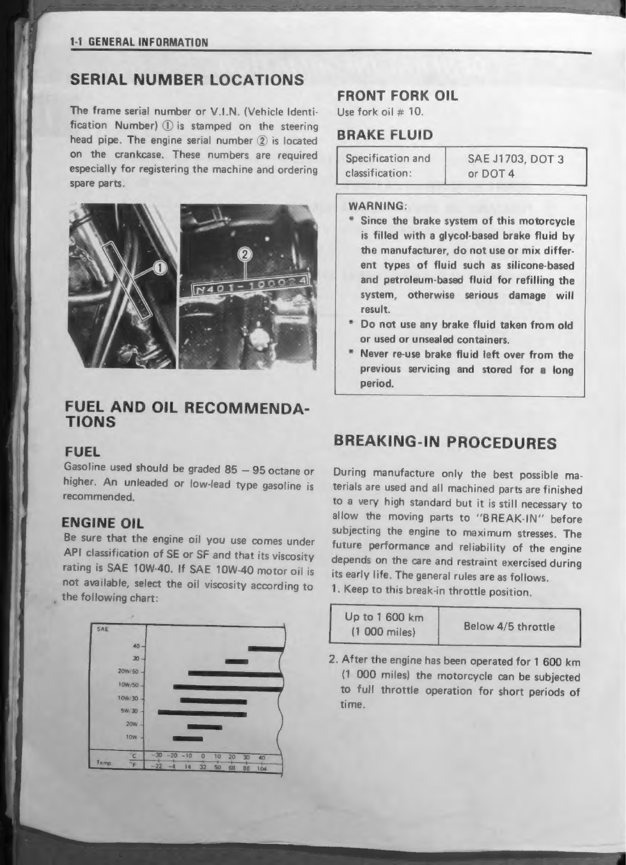
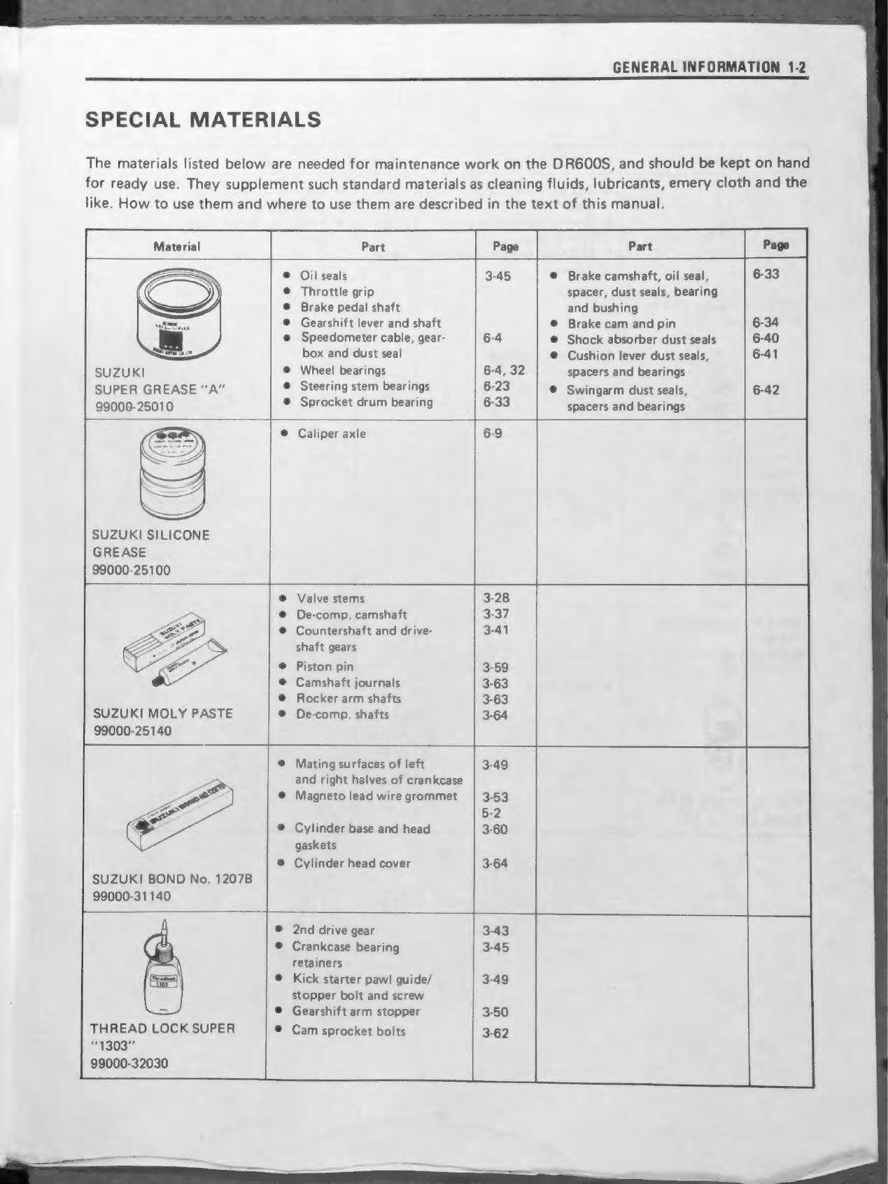
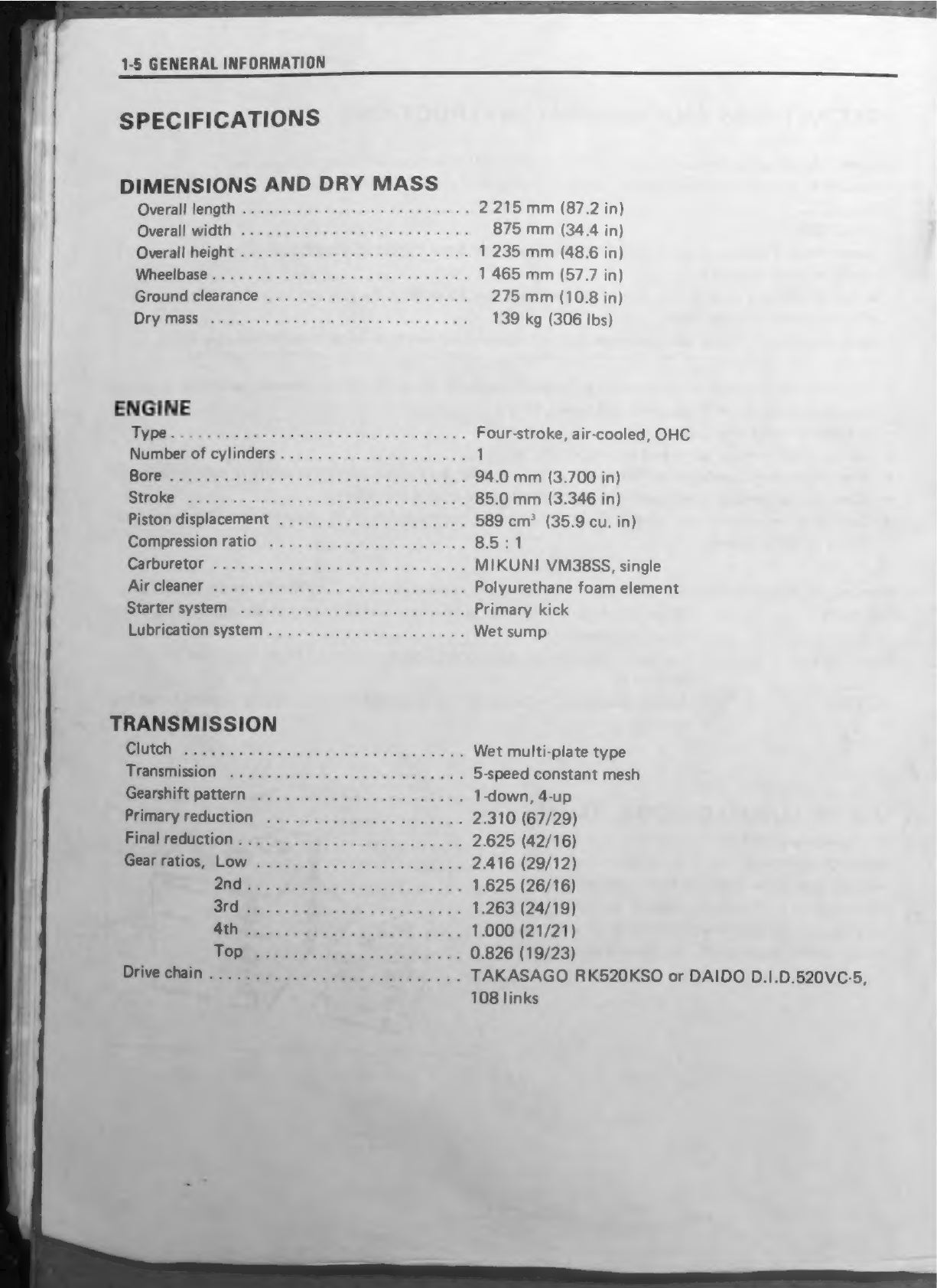
Suzuki DR600S User manual

SUZUKI
ORGOO"
SERVICE
MANUAL
|
4

gr
i
tien
key
No
ios
2.&
#
FOREWORD
The
SUZUKI
DR6O00S
was
designed
to
offer
superior
performance
through
lightweight
design,
four
stroke-power
(TSCC
engine),
engine
counter-balancers
and
full-floating
suspen-
sion.
This
service
manual
has
been
produced
primarily
for
experienced
mechanics
whose
job
is
to
inspect,
adjust,
repair
and
service
Suzuki
Motorcycles.
Apprentice
mechanics
and
do-it-
yourself
mechanics
will
also
find
this
manual
to
be
an
extremely
useful
repair
guide.
This
manual
contains
up-to-date
information
at
the
time
of
publication.
The
rights
are
reserved
to
update
or
make
corrections
to
this
manual
at
any
time.
SUZUKI
MOTOR
CO.,LTD.
Motorcycle
Technical
Service
Department
©
COPYRIGHT
SUZUKI
MOTOR
CO.,
LTD.
1985

VIEW
OF
SUZUKI
DR6OOSF
(‘85—MODEL)
RIGHT
SIDE
LEFT
SIDE

GROUP
INDEX
GENERAL
INFORMATION
—lc
ile
FUEL
AND
LUBRICATION
SYSTEM
PERIODIC
MAINTENANCE
AND
TUNE-UP
PROCEDURES
SERVICING
ENGINE
ELECTRICAL
SYSTEM
ee.
CHASSIS
EE
SERVICING
INFORMATION
DR600SG/
DR500SG
(‘86—MODEL)
DR600RG/
DR500RG
(‘86—MODEL)
Bo
DR600RH/DR500RH
DR600SH/DR500SH
(87—MODEL)
|
10
ie
DR600SJ/DR600RJ
,.
DR500SJ/DR500RJ(
88—MODEL)
HE
APPENDIX
J
i20
DR600SK/RK
(‘'89-MODEL)
Ei

GENERAL
INFORMATION
CONTENTS
SERIAL
NUMBER
LOCATIONS
4h:
0-
on
--ae
e
FUEL
AND
OIL
RECOMMENDATIONS
0000000000000:
eee
BREAKING-IN
PROCEDURES
«+++++>--2520s--22++0duestutabrties
soxsUnass-onseas
SPECIAL
IVA
TERIA
LS
305:
0-8
ss
res
scarey
ane
eogeeae
ee
Cee
eaeaamatae>
ae
PRECAUTIONS
AND
GENERAL
INSTRUCTIONS
SPECTFICA
TIONS
005+
-02
fo
0cthies
sce
accatduaretant
dnensltses
ans
ues:
atv
Sena

1-1
GENERAL
INFORMATION
SERIAL
NUMBER
LOCATIONS
The
frame
serial
number
or
V.I.N.
(Vehicle
Identi-
fication
Number)
@
is
stamped
on
the
steering
head
pipe.
The
engine
serial
number
(2)
is
located
on
the
crankcase.
These
numbers
are
required
especially
for
registering
the
machine
and
ordering
spare
parts.
FUEL
AND
OIL
RECOMMENDA-
TIONS
FUEL
Gasoline
used
should
be
graded
85
—
95
octane
or
higher.
An
unleaded
or
low-lead
type
gasoline
is
recommended.
ENGINE
OIL
Be
sure
that
the
engine
oil
you
use
comes
under
API
classification
of
SE
or
SF
and
that
its
viscosity
rating
is
SAE
10W-40.
If
SAE
10W-40
motor
oil
is
not
available,
select
the
oil
viscosity
according
to
_
the
following
chart:
-%
-20 -10
0
10
20
30 40
=22_-4
14
32
SO
68
86
104
FRONT
FORK
OIL
Use
fork
oil
#
10.
BRAKE
FLUID
SAE
J1703,
DOT
3
or
DOT
4
Specification
and
classification:
WARNING:
*
Since
the
brake
system
of
this
motorcycle
is
filled
with
a
glycol-based
brake
fluid
by
the
manufacturer,
do
not
use
or
mix
differ-
ent
types
of
fluid
such
as
silicone-based
and
petroleum-based
fluid
for
refilling
the
system,
otherwise
serious
damage
will
result.
*
Do
not
use
any
brake
fluid
taken
from
old
or
used
or
unsealed
containers.
Never
re-use
brake
fluid
left
over
from
the
previous
servicing
and
stored
for
a
long
Period.
*
BREAKING-IN
PROCEDURES
During
manufacture
only
the
best
possible
ma-
terials
are
used
and
all
machined
parts
are
finished
to
a
very
high
standard
but
it
is
still
necessary
to
allow
the
moving
parts
to
‘‘BREAK-IN”
before
subjecting
the
engine
to
maximum
stresses.
The
future
performance
and
reliability
of
the
engine
depends
on
the
care
and
restraint
exercised
during
its
early
life.
The
general
rules
are
as
follows.
1.
Keep
to
this
break-in
throttle
position.
Below
4/5
throttle
2.
After
the
engine
has
been
operated
for
1
600
km
(1
000
miles)
the
motorcycle
can
be
subjected
to
full
throttle
operation
for
short
periods
of
time.
Up
to
1
600
km
(1
000
miles)

SPECIAL
MATERIALS
The
materials
listed
below
are
needed
for
maintenance
work
on
the
DR6OOS,
and
should
be
kept
on
hand
for
ready
use.
They
supplement
such
standard
materials
as
cleaning
fluids,
lubricants,
emery
cloth
and
the
GENERAL
INFORMATION
1-2
like.
How
to
use
them
and
where
to
use
them
are
described
in
the
text
of
this
manual.
Material
Part
Part
SUZUKI
SUPER
GREASE
“A”
99000-25010
Oil
seals
Throttle
grip
Brake
pedal
shaft
Gearshift
lever
and
shaft
Speedometer
cable,
gear-
box and
dust
seal
Wheel
bearings
Steering
stem
bearings
Sprocket
drum
bearing
Brake
camshaft,
oil
seal,
spacer,
dust
seals,
bearing
and
bushing
Brake
cam
and
pin
Shock
absorber
dust
seals
Cushion
lever
dust
seals,
spacers
and
bearings
Swingarm
dust
seals,
spacers
and
bearings
SUZUKI
SILICONE
GREASE
99000-25100
Caliper
axle
SUZUKI
MOLY
PASTE
99000-25140
Valve
stems
De-comp.
camshaft
Countershaft
and
drive-
shaft
gears
Piston
pin
Camshaft
journals
Rocker
arm
shafts
De-comp.
shafts
SUZUKI
BOND
No.
1207B
99000-31140
Mating
surfaces
of
left
and
right
halves
of
crankcase
Magneto
lead
wire
grommet
Cylinder
base
and
head
gaskets
Cylinder
head
cover
THREAD
LOCK
SUPER
1303”
99000-32030
2nd
drive
gear
Crankcase
bearing
retainers
Kick
starter
pawl
guide/
stopper
bolt
and
screw
Gearshift
arm
stopper
Cam
sprocket
bolts

Material
1-3
GENERAL
INFORMATION
Part
Part
Page
*
THREAD
LOCK
SUPER
“1360”
99000-32130
@
Gearshift
cam
stopper
3-48
Magneto
stator
coil
5-2
bolt
securing
screws
@
Gearshift
cam
guide/paw!
3-50
Front
fork
damper
rod
6-16
lifter
screws
bolts
@
Engine
oil
pump
mounting
3-54
screws
THREAD
LOCK
“1342”
99000-32050
|
@
Magneto
rotor
bolt
3-53
THREAD
LOCK
SUPER
"1305"
99000-32100
if
©
Disc
mounting
bolts
6-8
v
SUZUKI
BRAKE
FLUID
99000-23021
(0.5
L)
|e
Front
brake

GENERAL
INFORMATION
1-4
PRECAUTIONS
AND
GENERAL
INSTRUCTIONS
Observe
the
following
items
without
fail
when
disassembling
and
reassembling
motorcycles.
e
Be
sure
to
replace
packings,
gaskets,
circlips,
O-rings
and
cotter
pins
with
new
ones.
CAUTION.
Never
reuse
a
circlip.
After
a
circlip
has
been
removed
from
a
shaft,
it
should
be
discarded
and
a
new
circlip
must
be
installed.
When
installing
a
new
circlip,
care
must
be
taken
not
to
expand
the
end
gap
larger
than
required
to
slip
the
circlip
over
the
shaft.
After
installing
a
circlip,
always
insure
that
it is
completely
seated
in
its
groove
and
securely
fitted.
®
Tighten
bolts
and
nuts
from
the
ones
of
larger
diameter
to
those
of
smaller
diameter,
and
from
inside
to
outside
diagonally,
with
specified
tightening
torque.
e
Use
special
tools
where
specified.
e
Use
specified
genuine
parts
and
recommended
oils.
e
When
more
than
2
persons
perform
work
in
cooperation,
pay
attention
to
the
safety
of
each
other.
e
After
the
reassembly,
check
parts
for
tightening
condition
and
operation.
e
Treat
gasoline,
which
is
extremely
flammable
and
highly
explosive,
with
greatest
care.
Never
use
gaso-
line
as
cleaning
solvent.
Warning,
Caution
and
Note
are
included
in
this
manual
occasionally,
describing
the
following
contents.
MOORS
INNINGS
5
cha.
sere
oe
Personal
safety
of
the
rider
is
involved,
and
disregard
of
the
information
could
result
in
injury.
GATHON
oodce
te
ones
sews
For
the
protection
of
the
motorcycle,
the
instruction
or
rule
must
be
strictly
adhered
to.
DUNN
eri
tics
wesc
veoe
«tose
Advice
calculated
to
facilitate
the
repair
of
the
motorcycle
is
given
under
this
heading.
USE
OF
SUZUKI
GENUINE
PARTS
To
replace
any
part
of
the
machine,
use
a
genuine
SUZUKI
replacement
part
or
an
equivalent.
Imita-
tion
parts
or
parts
supplied
from
any
other
source
than
SUZUKI,
if
used
to
replace
SUZUKI
Parts,
can
reduce
the
machine’s
performance
and,
even
worse,
could
induce
costly
mechanical
troubles.

1-5
GENERAL
INFORMATION
SPECIFICATIONS
DIMENSIONS
AND
DRY
MASS
CO
TANCE
8
Be
oe
ea
Overall
width
Overall
height
Wheelbase
Ground
clearance
ie
ES
GIGI
ess
oa
ENGINE
eS
ee
Petre
See
eG
be
ose
See
a
des
Piston
displacement
Compression
ratio
Carburetor
Air
cleaner
Starter
system
Lubrication
system
TRANSMISSION
Clutch
Gearshift
pattern
Primary
reduction
Final
reduction
Drive
chain
2
215
mm
(87.2
in)
875
mm
(34.4
in)
1
235
mm
(48.6
in)
1
465
mm
(57.7
in)
275
mm
(10.8
in)
139
kg
(306
Ibs)
Four-stroke,
air-cooled,
OHC
94.0
mm
(3.700
in)
85.0
mm
(3.346
in)
589
cm?*
(35.9
cu.
in)
8.5:1
MIKUNI
VM38SS,
single
Polyurethane
foam
element
Primary
kick
Wet
sump
Wet
multi-plate
type
.
5-speed
constant
mesh
.
1-down,
4-up
2.310
(67/29)
2.625
(42/16)
2.416
(29/12)
1.625
(26/16)
1.263
(24/19)
1.000
(21/21)
0.826
(19/23)
TAKASAGO
RK520KSO
or
DAIDO
D.1.D.520VC-5,
108
links

GENERAL
INFORMATION
146
ELECTRICAL
[GnithOn
AV
pees...
as
tee
ie
ee
SUZUKI
“PEI”
Kefothitelotadianttal
tecture
sce
tay
eee
ee
Ne
0°
B.T.D.C.
Below
2
200
r/min
and
30°
B.T.D.C.
Above
4
300
r/min
Spark)
PlUg-
scx:.cke.ahernc
ave
«eect
anode
eee
NGK
DP9EA-9
or
NIPPON
DENSO
X27EP-U9
(For
E-01,
24,
25
and
34)
NGK
DPR9EA-9
or
NIPPON
DENSO
X27EPR-U9
(For
others)
Battery
t.
aciewke-ce
a
no
eutsinaros
ei
ee
12V
18kC
(5
Ah)/10
HR
GON
GATOR
ratiig
ir
rua
cetera:
See
eee
Three-phase
A.C.
generator
FUSE
tenets
sc
Sehocos
Hatake
Ree
eh
ee
ees
15A
CHASSIS
PPVSME
SUMEMIPISID
oid.
ox
ny
edwin
ca
6
9:0
we
at
eoat
Telescopic,
pneumatic/coil
spring,
oil
dampened
FIGHT
AMMO
TMOM
irs
ding
case
5,
sieta
eta
Full
floating
suspension
system,
gas/oil
dampened,
spring
5-way
adjustable
BRUBEIN
rani
eid
a.
&
asia.
sin
gs
alain
tatareumme
ie
45°
(Right
&
Left)
(ATCT
RNEL
oe
Sle:
Sone
aap
mo
ueee
©
SOR
be
Y
@
60°
00’
BUG
SAL
Np
eipa
Accrtatss
5
ce
av
Sore.
wy
dyatee
revere
Rua
ree
eh
125
mm
(4.92
in)
PUL
CRONE:
ove
aie
g
charts
oophemte
w
Way
viatehaete
2.3
m
(7.5
ft)
FGrarit
BLAKE:
Gon
sevrteen.
cgchaceete-
ann
each
Disc
brake,
hydraulically
operated
ABA
DRE
KA
to.totii
cies:
bso
een
ome
cmtie
Internal
expanding
PONTE
MIZE
xo)
«
cugnatetetal
ceaeenereent
ont
ha
cet
aie
100/80-21
56S
say
Soe
othe
ROMs
Ce
130/80-17
65S
CAPACITIES
Fuel
tank
including
reserve...............
21L
(5.5/4.6
US/Imp
gal)
FORBUVE
rate
sata
ain
4.5
L
(4.8/4.0
US/Imp
qt)
ENGINE
Ol
cementing
To
RRitent
iss
+
oa).
2.3
L
(2.4/2.0
US/Imp
qt)
EQONUHORMVOH
tarexatiworee.cewle
es
kp
ean
wh
creas
475
ml
(16.1/16.7
US/Imp
oz)
These
specifications
are
subject
to
change
without
notice.

led
11
(0)
0)
fom
eV
ea
a
eee
TUNE-UP
PROCEDURES
CONTENTS
PERIODIC
MAINTENANCE
SCHEDULE
MAINTENANCE
AND
TUNE-UP
PROCEDURES
°*°---:0+0-0000-""
1-9
W
iy
f
1)
COPPER
CREE
RECEP,
PREPS
EE
Tre
Or
re
eS
|
CO
CYLINDER
HEAD
NUTS,
EXHAUST
PIPE
BOLTS
AND
MUFFLER
CONNECTIONS.
<+-++++ss++ssessessesseeseeseeseesenes
AIR
CLEANER:
ELEMENT
-2---2-<2--202-20<0s
0002s
s0secnevnsesuse>
bern
ed
sone
AUTOMATIC
DE-COMPRESSION
LEVER
+++-+--0-0000000000
VALVE
CLEARANCE
6
occa
ek
‘SPARK
PL
UG
Sissons
eres
aga
sven
sae
duntnetnuges
torueatodacn
wwesensomessdaee
iby
Lihie
os
eee
ee
ee
ENGINE
OFL
AND
OIL
FILTER
<++-<s+<2065---+<05-c2y0nevzcovansacenaten
CARBURETOR
BALANCER
CHAIN:
srr
cr
reece
cere
ete
ee
eee eee
e
eee
n
eee
e
cece
ee
eeeeeeeeenene
STEERING
AAA
Penne
eee
n
eens
anaes
eneneneeeeserenesseesseessseeeenernsesasessessseese
FRONT
FORK
TERR
nee
eee
e
ener
eee eee
seen
a
eeae
sees
eee
esse
eeeeseseeesessssssesesses
CHASSIS
BOLTS
AND
NUTS
Seen
ene
cere
een
eseceneensenenscsenseesecs

PERIODIC
MAINTENANCE
SCHEDULE
2-1
PERIODIC
MAINTENANCE
AND
TUNE-UP
PROCEDURES
The
chart
below
lists
the
recommended
intervals
for
all
the
required
periodic
service
work
necessary
to
keep
the
motorcycle
operating
at
peak
performance
and
economy.
Mileages
are
expressed
in
terms
of
kilometers,
miles
and
time
for
your
convenience.
NOTE:
More
frequent
servicing
may
be
performed
on
motorcycles
that
are
used
under
severe
conditions.
PERIODIC
MAINTENANCE
CHART
INTERVAL:
THIS
INTERVAL
SHOULD
BE
JUDGED
BY
ODOMETER
READING
OR
MONTHS
WHICHEVER
COMES
FIRST
Battery
(Specific
gravity
of
electrolyte)
Cylinder
head
nuts,
exhaust
pipe
bolts
and
muffler
connections
Air
cleaner
element
Automatic
de-compression
lever
Valve
clearance
Spark
plugs
Fuel
line
Fuel
strainer
Replace
every
fou
—
Engine
oil
and
oil
filter
Carburetor
idle
rpm
Balancer
chain
Clutch
Drive chain
Brakes
and
lubricate
every
1
000
km
(600
miles).
nspect
every
3
000
km
(2
000
miles).
Brake
hoses
aeenes.4
Replace
every
four
years.
Brake
fluid
Change
every
two
years.
Tires
Steering
Front
forks
Chassis
bolts
and
nuts
NOTE:
T
=
Tighten,
|
=
Inspect,
R=
Replace,
C=
Clean

PERIODIC
MAINTENANCE
AND
TUNE-UP
PROCEDURES
2-2
OILING
POINTS
Proper
lubrication
is
important
for
smooth
operation
and
long
life
of
each
working
part.
Major
oiling
points
are
indicated
below.
G:
Throttle
grip
:
Throttle
cabl
3
ee
M
@:
Brake
lever
holder
:
Rear
suspension
bearing
A
and
dust
seal
‘
P
vA
&
J:
Steering
stem
bearing
&:
Swingarm
pivot
bearing
i?
.
and
dust
seal
_o:
Speedometer
cable
G:
Brake
pedal pivot
&.
,.
;
ae
“ee:
@:
Kick
starterlever
pivot
@:
Spherical
ball
bearing
and
dust
seal
@:
Clutch
cable
and
clutch
lever
holder
|
@:
Manual
De-comp.
cable
)
@:
Automatic
De-comp.
cable
We.
Motor
oil
G:
Side
stand
pivot
Grease
@:
Gearshift
lever
pivot
NOTE:
*
Lubricate
exposed
parts
which
are
subject
to
rust,
with
a
rust
preventative
spray
whenever
the
motorcycle
has
been
operated
under
wet
or
rainy
conditions.
If
the
spray
is
unavailable,
use
either
motor
oil
or
grease.
*
Before
lubricating
each
part,
clean
off
any
rusty
spots
and
wipe
off
any
grease,
oil,
dirt
or
grime.
L
[
WARNING:
ral
Be
careful
not
to
apply
too
much
grease
to
the
brake
cam
shaft.
If
grease
gets
on
the
linings,
brake
ie
slippage
will
result.
=

2-3
PERIODIC
MAINTENANCE
AND
TUNE-UP
PROCEDURES
MAINTENANCE
AND
TUNE-UP
PROCEDURES
This
section
describes
the
servicing
procedures
for
each
item
of
the
Periodic
Maintenance
require-
ments.
BATTERY
Inspect
Every
6
000
km
(4
000
miles)
e@
Remove
the
frame
covers
and
seat.
(Refer
to
page
3-2)
e@
Check
electrolyte
for
level
and
specific
gravity.
Add
distilled
water,
as
necessary
to
keep
the
surface
of
the
electrolyte
above
the
MIN.
level
line
but
not
above
the
MAX.
level
line.
e
For
checking
specific
gravity,
use
a
hydrometer
to
determine
the
charged
condition.
cee
weenie
1.28
at
20°C
(68°F)
gravity
An
S.G.
reading
of
1.22
(at
20°C)
or
under
means
that
the
battery
needs
recharging.
Remove
the
battery
from
the
motorcycle
and
charge
it
with
a
battery
charger.
|
CauTioN:
*
When
removing
the
battery
from
the
motorcycle,
be
sure
to
disconnect
the
©
lead
wire
first.
*
Never
charge
a
battery
while
still
in
the
motorcycle
as
damage
may
result
to
the
battery
or
regulator/rectifier.
*
Be
careful
not
to
bend,
obstruct,
or
change
the
routing
of
the
breather
pipe
from
the
battery,
make
certain
that
the
breather
pipe
is
attached
to
the
battery
vent
fitting
and
that
the
opposite
end
is
always
open.
*
When
installing
the
battery
lead
wires,
fix
the
@
lead
first
and
©
lead
last.
a
e@
Make
sure
that
the
breather
pipe
is
tightly
secured
and
undamaged,
and
is
routed
as
shown
in
the
figure.
Hydrometer
Battery
breather
pipe

PERIODIC
MAINTENANCE
AND
TUNE-UP
PROCEDURES
24
CYLINDER
HEAD
NUTS,
EXHAUST
PIPE
BOLTS
AND
MUFFLER
CONNECTIONS
Tighten
Initial
1
000
km
(600
miles)
and
Every
6
000
km
(4
000
miles)
CYLINDER
HEAD
e
Remove
the
frame
covers,
seat
and
fuel
tank.
(Refer
to
page
3-2)
e
Remove
the
cylinder
head
cover.
(Refer
to
page
3-11)
e
Disconnect
the
de-comp.
cables,
automatic
and
manual.
(Refer
to
page
3-4)
e
First
loosen
and
retighten
the
four
10-mm
@
and
two
8-mm
@)
nuts
to
the
specified
torque
with
a
torque
wrench
sequentially
in
diagonally
with
the
engine
cold.
35
—40N-.m
(
3.5
—
4.0
kg-m
)
25.5
—
29.0
Ib-ft
torque
23
—27N-m
(
2.3
—
2.7
kg-m
)
16.5
—
19.5
Ib-ft
Tightening
e
After
firmly
tightening
the
six
nuts,
tighten
the
two
6-mm
nuts
(indicated
as
@))
to
the
torque
value
below:
7-—11N-m
Tightening
torque
@)
ee
—11
a
5.0
—
8.0
Ib-ft
e@
When
installing
the
cylinder
head
cover,
apply
SUZUKI
Bond
No.
12078
to
the
mating
surface.
(Refer
to
page
3-64)
EXHAUST
PIPE
AND
MUFFLER
©
Tighten
the
exhaust
pipe
bolts,
muffler
connec-
tion bolt
and
muffler
mounting
bolts to
the
specified
torque
with
a
torque
wrench.
Tightening
torque
9-—12N-m
Exhaust
pipe
bolts
@)
is
—
1.2
kg-m
6.5-—8.5
ay
Muffler
connection
and
18
—
28
N.m
muffler
mounting
bolts
(
1.8
—
2.8
kg-m
)
®
13.0
—
20.0
Ib-ft

2-5
PERIODIC
MAINTENANCE
AND
TUNE-UP
PROCEDURES
AIR
CLEANER
ELEMENT
Clean
Every
3
000
km
(2
000
miles)
lf
the
air
cleaner
is
clogged
with
dust,
intake
resistance
will
be
increased
with
a
resultant
decrease
in
power
output
and
an
increase
in
fuel
consump-
tion.
Check
and
clean
the
element
in
the
following
manner.
Remove
the
frame
covers
and
seat.
(Refer
to
page
3-2)
Remove
the
air
cleaner
case
cover
by
loosening
screw
(1).
Remove
the
wing
nut
(2)
and
take
off
the
air
cleaner
element.
Remove
the
polyurethane
foam
element
(3)
from
the
element
frame
@).
Fill
a
washing
pan
of
a
proper
size
with
non-
flammable
cleaning
solvent.
Immerse
the
ele-
ment
in
the
cleaning
solvent
and
wash
it
clean.
Squeeze
the
cleaning
solvent
out
of
the
washed
element
by
pressing
it
between
the
palms
of
both
hands.
Immerse
the
element
in
motor
oil,
and
squeeze
the
oil
out
of
the
element
leaving
it
slightly
wet
with
oil.
NOTE:
Do
not
twist
or
wring
the
element
because
it
will
tear
or
the
individual
cells
of
the
element
will
be
damaged.
CAUTION:
Inspect
the
element
carefully
for
rips,
torn
seams,
etc.
If
any
damage
is
noted,
replace
the
element.
Non-flammable
ges
cleaning
solvent
=>
ae
ae
a
“
«
|
SAE
10W/40
OIL
=:

PERIODIC
MAINTENANCE
AND
TUNE-UP
PROCEDURES
246
AUTOMATIC
DE-COMPRESSION
LEVER
Inspect
Initial
1
000
km
(600
miles)
and
Every
6
000
km
(4
000
miles)
Incorrect
adjustment
of
the
lever
free
play
may
result
in
starting
difficulties
or
engine
damage.
Check
the
lever
free
play
and
if
necessary,
adjust
as
follows:
e
Remove
the
spark
plug
and
valve
timing
inspec-
tion
plug.
e
Remove
the
magneto
cover
cap
and
turn
the
crankshaft
counterclockwise
with
the
box
wrench
to
set
the
piston
at
T.D.C.
on
the
com-
pression
stroke.
(Refer
to
page
2-7)
e
Loosen
both
lock
nuts
(1)
on
the
cable
adjuster
2).
e
Locate
the
adjuster
(2)
to
provide
the
specified
play.
@
Tighten
the
both
lock
nuts
(1).
VALVE
CLEARANCE
Inspect
Initial
1
000
km
(600
miles)
and
|
Every
6
000
km
(4
000
miles)
Excessive
valve
clearance
results
in
valve
noise
and
insufficient
valve
clearance
results
in
valve
damage
and
reduced
power.
At
the
distances
indicated
above,
check
and
adjust
the
clearance
to
the
specification.
The
procedure
for
adjusting
the
valve
clearance
is
as
follows:
When
the
de-compression
cable
play
is
properly
adjusted,
the
de-compression
lever
should
have
1
—
2
mm
of
free
play
with
the
piston
at
T.D.C.
on
the
compression
stroke.
1—2mm
(0.04
—
0.08
in)
De-compression
lever
play
@
NOTE:
Valve
clearance
is
to
be
checked
when
the
engine
is
cold.
Both
the
intake
and
exhaust
valves
must
be
checked
and
adjusted
when
the
piston
is
at
Top—Dead—Center
(TDC)
on
the
compression
stroke.
Remove
the
seat,
frame
covers
and
fuel
tank.
(Refer
to
page
3-2)
Remove
the
spark
plug
and
valve
inspection
caps,
intake
and
exhaust.
(Refer
to
page
3-11)
CAUTION:
Before
adjusting
the
valve
clearance,
check
or
adjust
the
automatic
decompression
lever
play.
Valve
clearance
specifications
IN.
and
EX.
0.08
—
0.13
mm
(0.003
—
0.005
in)

2-7
PERIODIC
MAINTENANCE
AND
TUNE-UP
PROCEDURES
e@
Remove
the
valve
timing
inspection
plug
and
magneto
cover
cap.
e
Turn
the
crankshaft
counterclockwise
with
the
box
wrench
to
set
the
piston
at
T.D.C.
on
the
compression
stroke.
(Turn
the
crankshaft
until
the
“T”
line
on
the
magneto
rotor
is
aligned
with
the
center
of
hole
on
the
magneto
cover.)
@
Insert
the
thickness
gauge
into
the
clearance
between
the
valve
stem
end
and
the
adjusting
screw
on
the
rocker
arm.
e
If
clearance
is
off
the
specification,
bring
it
into
the
specified
range
by
using
the
screw
driver.
Securely
tighten
the
lock
nut
after
adjustment
is
completed.
CAUTION:
Both
the
right
and
left
valve
clearances,
should
be
as
closely
set
as
possible.
—t
NOTE:
Make
sure
to
recheck
the
automatic
de-
compression
lever
play,
after
valve
clearance
adjustment
is
made.
e
Reinstall
the
spark
plug,
valve
inspection
caps,
valve
timing
inspection
plug
and
magneto
cover
cap.
MANUAL
DE-COMPRESSION
LEVER
e
After
adjusting
the
valve
clearance,
adjust
the
de-compression
cable.
@
With
the
de-compression
lever
squeezed,
loosen
and
adjust
the
two
adjuster
lock
nuts
so
that
the
clearance
between
the
lever
on
the
engine
and
upper
cylinder
head
cover
becomes
zero
as
indicated
in
Fig.
at
right.
©
After
adjusting
the
cable
correctly,
tighten
the
two
lock
nuts.
S
wii
Lock
nut
Lock
nut
Cylinder
head
cover

PERIODIC
MAINTENANCE
AND
TUNE-UP
PROCEDURES
2-8
SPARK
PLUGS
Clean
Every
6
000
km
(4
000
miles)
and
Replace
Every
12
000
km
(7
500
miles)
The
plug
gap
is
adjusted
to
0.8
—
0.9
mm
(0.03
—
0.04
in).
The
gap
is
correctly
adjusted
by
using
a
thickness
gauge.
When
carbon
is
deposited
on
the
spark
plug,
remove
the
carbon
with
a
tool
with
a
pointed
end.
If
the
electrodes
are
extremely
worn
or
burnt,
replace
the
plug.
Also
replace
the
plug
if
it
has
a
broken
insulator,
damaged
thread,
etc.
NGK
DP9EA-9
or
NIPPON
DENSO
X27EP-U9
as
listed
in
the
table
should
be
used
as
the
standard
plug.
However,
the
heat
range
of
the
plug
should
be
selected
to
meet
the
requirements
of
speed,
actual
load,
fuel,
etc.
If
the
plugs
need
to
be
replaced,
it
is
recommended
that
the
standard
plugs
listed
in
the
table
be
selected.
Remove
the
plugs
and
inspect
the
insulators.
Proper
heat
range
would
be
indicated
if
all
insulators
were
light
brown
in
color.
If
they
are
blackened
by
carbon,
they
should
be
replaced
by
a
hot
type
NGK
DP8EA-9
or
NIPPON
DENSO
X24EP-U9.
NOTE:
To
check
the
spark
plugs,
first
make
sure
that
the
fuel
tank
contains
unleaded
gasoline,
and
after
a
test
ride
if
the
plugs
are
either
sooty
with
carbon
or
burnt
white,
replace
them.
_——
NOTE:
Confirm
the
thread
size
and
reach
when
replacing
the
plug.
If
the
reach
is
too
short,
carbon
will
be
deposited
on
the
screw
portion
of
the
plug
hole
and
engine
damage
may
result.
Gap
0.8
—
0.9mm
(0.03
—
0.04
in)
NIPPON
DENSO
REMARKS
NGK
If
the
standard
plug
is
apt
to
get
wet,
replace
it
|
with
this
hot
type
plug.
DP8EA-9
X24EP-U9
DP9EA-9
X27EP-U9
“R”’
type
spark
plug
NIPPON
DENSO
NGK
REMARKS
If
the
standard
plug
is
apt
to
get
wet,
replace
it
with
this
hot
type
plug.
NOTE:
“R”
type
spark
plug
is
installed
for
some
specifications.
“‘R’”
type
spark
plug
has
a
resister
located
at
the
center
electrode
to
prevent
radio
noise.
DPR8EA-9
X24EPR-U9
This manual suits for next models
15
Other Suzuki Motorcycle manuals

Suzuki
Suzuki VLR1800 User manual

Suzuki
Suzuki 700 User manual

Suzuki
Suzuki 1989 GS500EK User manual

Suzuki
Suzuki AN650 User manual

Suzuki
Suzuki T250 User manual

Suzuki
Suzuki GS1100E User manual

Suzuki
Suzuki GSX650F Manual

Suzuki
Suzuki Intruder VZ800 User manual

Suzuki
Suzuki GSR600 User manual

Suzuki
Suzuki Katana 1100 User manual

Suzuki
Suzuki RM-Z250L9 User guide

Suzuki
Suzuki rg500 User manual

Suzuki
Suzuki Intruder VS600GL User manual

Suzuki
Suzuki GS500/F User manual

Suzuki
Suzuki GSX-R750 User manual

Suzuki
Suzuki GSX-R1000 User manual

Suzuki
Suzuki DR-Z70 User manual

Suzuki
Suzuki gsr750 Manual

Suzuki
Suzuki DL650 User manual

Suzuki
Suzuki FL125S User manual