Foreword
This
manual
is designed
primarily
for
use by
snow-
mobile mechanics in a properly equipped shop.
However,
it
contains enough detail and basic
in-
formation
to make
it
useful to the snowmobile user
who
desires to perform his
own
basic
mainte-
nance and repair
work
. A basic knowledge
of
mechanics, the proper use
of
tools, and workshop
procedures
must
be understood in order to carry
out
maintenance and repair satisfactorily.
When-
ever the
owner
has
insufficient
experience
or
doubts his ability to do the work, the adjustments,
maintenance, and repair should be carried
out
only
by qualified mechanics.
In order to perform the
work
efficiently
and to
avoid costly mistakes, the mechanic should read
the
text, thoroughly familiarize
himself
with
the
procedures before starting work, and
then
do
the
work
carefully in a clean area.
Whenever
special
tools
or
equ ipment is specified, makeshift tools or
equipment
should
not
be used. Precision measure-
ments
can only
be
made
if
the proper
instruments
are used, and the use
of
substitute tools may
adversely affect safe operation
of
the
snowmobile.
Whenever
you see
the
symbols
shown
below, heed
their
instructionsI
Always
follow
safe operating
and maintenance practices.
IWARNINGI
This
warning
symbol
identifies
special
in-
structions
or
procedures
which
if
not
cor-
rectly
followed
,
could
result
in
personal
injury,
or
loss
of
life.
This
caution
symbol
identifies
special
in-
structions
or
procedures
which
if
not
strictly
observed,
could
result
in
damage to,
or
destruction
of
equipment
.
NOTE:
Indicates points
of
particular interest
for
more
efficient
and convenient operation.
This manual is divided
into
the
following
four
sections:
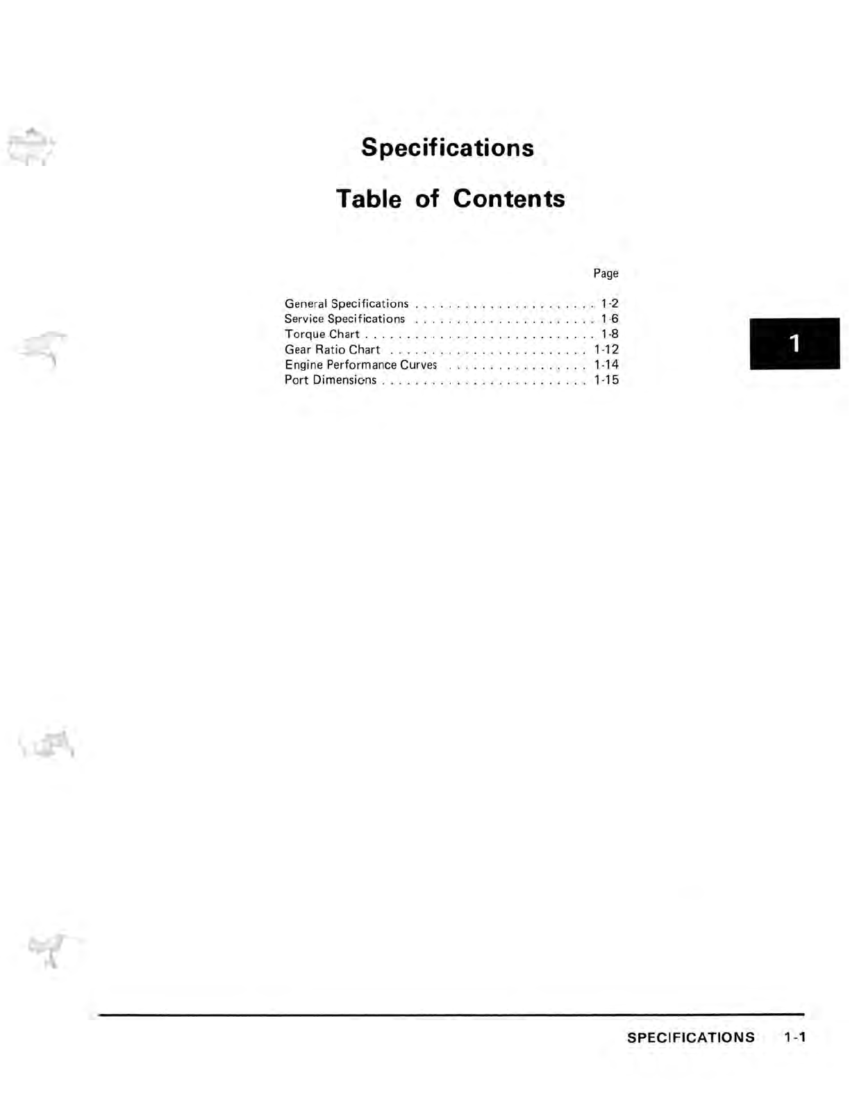
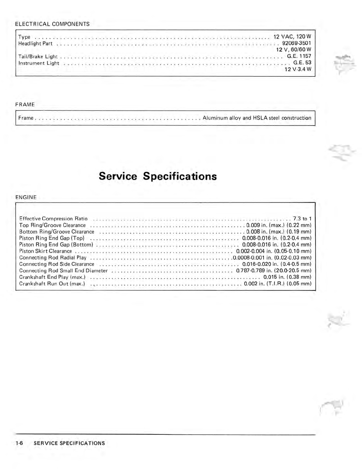
(1) Specifications
This section contains general and technical specifi-
cations, a complete torque chart and engine per-
formance
cu
rves.
(2)
Maintenance
and Theory
of
Operation
The procedures
for
inspection, adjustments and
minor
repair are described in
this
section.
An
explanation on the
structure
and
function
of each
of
the
major
components and assembly enables
the mechanic
to
better understand
what
he is
doing.
(3) Repair
This section shows the best method
for
removal,
disassembly, inspection, assembly, and installation
which
are necessary
for
proper
maintenance and
repair. Assembly and
installation
notes are pro-
vided to explain special points.
(4)
Appendix
The appendix in the back
of
the
manual
contains
miscellaneous
information,
including
metric
refer-
ence and conversion charts, special tools,
wiring
diagram, and an index.
This shop manual has been prepared to assist the
mechanic in servicing
the
KAWASAKI
snow-
mobiles.
All
procedures contained
within
should be
followed closely.
FOREWORD


 Supplementary service manual")