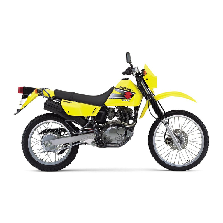
Suzuki RM85K4 2003 Reference manual

HAMAMATSU-NISHI P.O. BOX 1, 432-8611 HAMAMATSU, JAPAN.
MOTERCYCLE
DATE:
Jun. 1, 2003
PAGE:
1
OF
8
SUBUJECT:
NOTICE OF SET-UP MANUAL
APPLICABLE MODEL:
RM85K4/LK4
EFFECTIVE ENGINE OR FRAME NO.:
REFERENCE:
This bulletin is to inform you of set-up procedures of RM85K4/LK4. Please inform your dealers of
this notice.
RM85K4/LK4 set-up manual will not be issued because the set-up procedures for this model
remain unchanged from RM85K2 except the differences described below.
To set-up RM85K4/LK4, please use the RM85K2 set-up manual and this service bulletin.
DIFFERENCE BETWEEN RM85K2 AND RM85K4/LK4
RM85K2 set-up manual: 99505-01032-011
1. LOCATION OF PARTS [Page: 2, 4, 6]
Item Part Name Q’ty Remarks
A
Number plate 1
Flange bolt 1 6 × 20 mm
Washer 1 OD:14.0 ID:6.5
B Radiator louver 1
C
Handlebars assembly 1
Clamp 2
Flange bolt 4 8 × 35 mm
Clutch lever cover 1
Fuel tank vent hose 1
Screw 1 5 × 16 mm
For throttle assembly
Clamp 1 For throttle cable
Strap 2 L:120
Engine stop switch holder 2 Upper and lower
Screw (with lock washer) 1 3 × 14 mm
D
Radiator cover 1
*Flange bolt 36 × 12 mm
Stepped washer 3 OD:16.0 ID:6.5 T:3.5
EFront fork assembly 2 Right and Left
Flange bolt 6 8 × 40 mm
F
Seat assembly 1
Flange bolt 2 6 × 16 mm
Washer 2 OD:20.0 ID:6.5 T:1.6
G
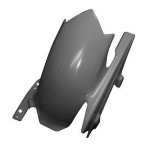
Rear fender 1
Washer 2 OD:26.0 ID:6.5
Flange bolt 3 6 × 30 mm
Washer 4 OD:20.0 ID:6.5 T:1.2
*Self-lock nut 26 mm
Flange bolt 1 6 × 20 mm
Washer 2 OD:18.0 ID:6.5 T:1.6
Flange self-lock nut 2 6 mm (Black)
Item Part Name Q’ty Remarks
H
Front fender 1
Flange bolt 4 6 × 16 mm
Stepped washer 4 OD:16.0 ID:6.5 T:3.5
*Stepped washer 4OD:17.0 ID:6.5 T:6.0
I
Front axle 1
Front wheel spacer 2
Washer 1 OD:20.0 ID:12.5
Axle nut 1 12 mm
Cotter pin 1 L:27.0
J
Front brake hose cover 1
Flange bolt 2 6 × 12 mm
*Stepped washer 2OD:16.0 ID:6.5 T:3.5
KFront brake hose clip 2 Right and Left
*Flange bolt 26 × 16 mm
LFront brake hose guide 1
Flange bolt 1 6 × 20 mm
MFront fork protector 2 Right and Left
Flange bolt 6 6 × 10 mm
N Front wheel assembly 1
OFrame cover 2 Right and Left
Strap 2 L:140
*P Side stand assembly 1Spec is eliminated.
Flange bolt 2
Q
Main jet 3 Exchanging parts
Spark plug and spoke
nipple wrench 1
R Fuel label 1
S Owner’s manual 1
*T Stand 1
OD : Outside diameter (mm)
ID : Inside diameter (mm)
L : Length (mm)
T : Thickness (mm)
TL
OD ID

HAMAMATSU-NISHI P.O. BOX 1, 432-8611 HAMAMATSU, JAPAN.
MOTERCYCLE
DATE
: Jun. 1, 2003
PAGE
: 2
OF
8
2. SPARE PARTS [Page: 2, 4, 6]
3. ASSEMBLY
Part Name Q’ty
Piston pin bearing 1
Piston pin circlip 2
Cylinder head O-ring No.1 2
Cylinder head O-ring No.2 2
Cylinder cover gasket No.1 2
Cylinder cover gasket No.2 1
Cylinder gasket 2
Crankcase gasket 1
Clutch cover gasket 1
Piston complete 1
Piston pin 1
Piston ring 2
Exhaust valve rod bush 2
Exhaust flange O-ring 2
Brake lever 1
Clutch lever 1
FRONT FORK (RM85L) [Page: 9, 10]
!
!
Insert each fork leg assembly into the lower and
upper brackets. Adjust the line of front fork to the top
face of the upper bracket and air valve is positioned
at the front.
A: Caliper D: Line
B: Right fork leg E: Front fork upper bracket
C: Left fork leg F: Air pressure
FRONT FORK [Page: 11, 12 Paragraph: 1, 2]
Tighten the lower bracket side bolts to the specified
torque.
"
""
"Front fork lower bracket bolt:
23 N·m (2.3 kgf-m)
A: Front fork assembly
B: 8 × 40 mm flange bolt
Keep the position of front brake master cylin-
der with its cap facing upwards until it is
installed.
Install the front fork assembly with front brake
caliper to the left side.

HAMAMATSU-NISHI P.O. BOX 1, 432-8611 HAMAMATSU, JAPAN.
MOTERCYCLE
DATE
: Jun. 1, 2003
PAGE
: 3
OF
8
Tighten the upper bracket side bolts to the specified
torque.
"
""
"Front fork upper bracket bolt:
23 N·m (2.3 kgf-m)
A: Front fork assembly
B: 8 × 40 mm flange bolt
FRONT FENDER [Page: 13, 14 Paragraph: 2]
Install the front fender with four sets of mounting
parts as shown. Each of the four mounting bolts
requires two stepped washers.
A: Front fender
B: Stepped washer OD:17.0 mm ID:6.5 mm T:6.0 mm
C: Stepped washer OD:16.0 mm ID:6.5 mm T:3.5 mm
D: 6 × 16 mm flange bolt
STAND [Page: 17, 18 Paragraph: 2, 3]
Insert the boss of stand to the hole of frame as shown
in the photograph.
A: Stand
Place the motorcycle on the stand, then remove the
hoist hook.

HAMAMATSU-NISHI P.O. BOX 1, 432-8611 HAMAMATSU, JAPAN.
MOTERCYCLE
DATE
: Jun. 1, 2003
PAGE
: 4
OF
8
BRAKE HOSE CLIP [Page: 19, 20 Paragraph: 1]
Align the groove of front brake hose with the groove
of brake hose clip.
Install the brake hose clip to the front fork protector.
A: Brake hose clip
B: Front brake hose
C: Groove
D: 6 × 16 mm flange bolt
E: Front fork protector
FRONT BRAKE HOSE COVER
[Page: 19, 20 Paragraph: 2]
Install the front brake hose cover to the left fork leg.
A: Brake hose cover
B: 6 × 12 mm flange bolt
C: Stepped washer OD:16.0 mm ID:6.5 mm T:3.0 mm
REAR FENDER [Page: 25, 26 Paragraph: 3]
Install the rear fender with fitting parts as shown in
the photograph.
Securely tighten the two nuts Ifixed temporarily.
A: Rear fender
B: 6 × 20 mm flange bolt
C: 6 × 30 mm flange bolt
D: Washer OD:20.0 mm ID:6.5 mm T:1.2 mm
E: 6 mm self-lock nut
F: Frame
G: Spacer
H: Second muffler
I: 6 mm flange self-lock nut (Black)
J: Rubber cushion
K: Washer OD:18.0 mm ID:6.5 mm
RADIATOR COVER [Page: 27, 28 Paragraph: 3]
Install the radiator cover with flange bolt and stepped
washer.
A: Radiator cover
B: 6 × 12 mm flange bolt
C: Stepped washer OD:16.0 mm ID:6.5 mm T:3.5 mm

HAMAMATSU-NISHI P.O. BOX 1, 432-8611 HAMAMATSU, JAPAN.
MOTERCYCLE
DATE
: Jun. 1, 2003
PAGE
: 5
OF
8
4. SERVICING
40–50 mm
(1.6–2.0 in)
REAR BRAKE PEDAL
[Page: 35, 36 Paragraph: 1]
Check the rear brake pedal height.
Rear brake pedal height: 0–10 mm (0–0.4 in)
If the rear brake pedal height is not adjusted cor-
rectly, adjust in the following manner:
1. Loosen the lock nut A.
2. Adjust the brake pedal height by turning the
adjuster Bto locate the pedal to the correct height
below the top face of the footrest C.
3. Tighten the lock nut A.
DRIVE CHAIN [Page: 35, 36 Paragraph: 3, 4]
Check the drive chain slack.
Drive chain slack: 40–50 mm (1.6–2.0 in)
If it is too tight or too loose, follow these procedures.
Loosen the axle nut. Loosen the lock nut. Adjust the
slack in the drive chain by turning the right and left
chain adjuster bolts. Proper chain slack is obtained
when the drive chain slack is up and down, at a point
midway between the two sprockets.
A: Axle nut
B: Lock nut
C: Adjuster bolt
D: Reference marks
After adjusting, tighten the axle nut to the specified
torque. Tighten the lock nuts securely.
#$
"
""
"Rear axle nut: 72 N·m (7.2 kgf-m)
FRONT FORK [Page: 37, 38 Paragraph: 2, 3]
Rebound Damping Force Adjustment
Adjust the setting of the rebound damping force to
the standard position. To adjust, turn the adjuster
screw Aclockwise until it stops, then turn it counter-
clockwise until 1-1/8 turns are felt.
%
Make sure that the rear sprocket is properly
aligned with the engine sprocket. Verify the
reference marks on the swing-arm by sighting
down along the chain from the rear end of the
motorcycle.
Do not force the adjuster screw A
AA
Apast the
stopped position or you may damage the
adjuster. Be sure to adjust the damping force
on both front forks equally.
HAMAMATSU-NISHI P.O. BOX 1, 432-8611 HAMAMATSU, JAPAN.
MOTERCYCLE
DATE
: Jun. 1, 2003
PAGE
: 6
OF
8
Compression Damping Force Adjustment
Adjust the setting of the compression damping force
to the standard position. To adjust, turn the adjuster
screw Bclockwise until it stops, then turn it counter-
clockwise until 7 clicks are felt.
%
REAR SUSPENSION
[Page: 39, 40 Paragraph: 1, 2]
Rebound Damping Force Adjustment
(FOR RM85K4)
Adjust the setting of the rebound damping force to
the standard position. To adjust, turn the adjuster
screw Aclockwise until it stops and then turn it coun-
terclockwise until approximately 1-1/2 turns are felt
and the two punch marks align.
%
(FOR RM85LK4)
Adjust the setting of the rebound damping force to
the standard position. To adjust, turn the adjuster
screw Aclockwise until it stops and then turn it coun-
terclockwise until approximately 1-1/4 turns are felt
and the two punch marks align.
%
Compression Damping Force Adjustment
Adjust the setting of the compression damping force
to the standard position. To adjust, turn the adjuster
screw Bclockwise until it stops and then turn it coun-
terclockwise until approximately 1-3/4 turns are felt
and the two punch marks align.
%
Do not force the adjuster screw B
BB
Bpast the
stopped position or you may damage the
adjuster. Be sure to adjust the damping force
on both front forks equally.
Do not force the adjuster screw A
AA
Apast the
stopped position or you may damage the
adjuster.
Do not force the adjuster screw A
AA
Apast the
stopped position or you may damage the
adjuster.
Do not force the adjuster screw B
BB
Bpast the
stopped position or you may damage the
adjuster.

HAMAMATSU-NISHI P.O. BOX 1, 432-8611 HAMAMATSU, JAPAN.
MOTERCYCLE
DATE
: Jun. 1, 2003
PAGE
: 7
OF
8
[Page: 43, 44 Paragraph: 1]
!
!&(FOR CANADA)
!
Use 30 : 1 pre-mixture of unleaded gasoline
minimum 95 octane (RON) and oil. For the oil
to be mixed with gasoline, any of the following
brands or its equivalent will do.
*MOTUL 800 2T
Use 30 : 1 pre-mixture of unleaded gasoline
minimum 90 pump octane (R/2+M/2) and oil.
For the oil to be mixed with gasoline, any of
the following brands or its equivalent will do.
*MOTUL 800 2T
Do not allow two different brands to get mixed
in the fuel-oil mixture.
4. TIGHTENING TORQUE [Page: 45, 46, 47]
Item Part Name N·mkgf-m
FRONT FORK
A Handlebar clamp bolt 26 2.6
B Steering stem head nut 65 6.5
*C Front fork upper bracket bolt 23 2.3
*D Front fork lower bracket bolt 23 2.3
BRAKE
E Front brake caliper mounting bolt 23 2.3
F Front brake master cylinder mounting bolt 10 1.0
G Rear brake caliper mounting bolt 23 2.3
H Rear brake master cylinder mounting bolt 10 1.0
I Rear brake push rod lock nut 18 1.8
J Brake caliper air bleeder 7.5 0.75
Item Part Name N·mkgf-m
AXLE
K Front axle nut 44 4.4
*L Rear axle nut 72 7.2
ABSORBER
M Rear shock absorber nut (Upper) 60 6.0
N Rear shock absorber nut (Lower) 60 6.0
OTHERS
O Rear swing arm pivot nut 58 5.8

HAMAMATSU-NISHI P.O. BOX 1, 432-8611 HAMAMATSU, JAPAN.
MOTERCYCLE
DATE
: Jun. 1, 2003
PAGE
: 8
OF
8
5. HARNESS ROUTING [Page: 49]
CDI unit
Ignition coil
Cushion
Exhaust breather hose
Clamp
Clamp
Magneto lead wire
Engine stop switch
lead wire
CDI unit lead wire
Clamp
Magneto lead wire
Engine stop switch lead wire
Cushion
Revised
Revised
This manual suits for next models
1
Other Suzuki Motorcycle manuals

Suzuki
Suzuki VL125 User manual

Suzuki
Suzuki GSX-R1000 2007 User manual

Suzuki
Suzuki TU250X User manual

Suzuki
Suzuki RM-Z250 User manual

Suzuki
Suzuki GV1200GLG User manual

Suzuki
Suzuki GSX25 User manual

Suzuki
Suzuki GSX-R250 User manual

Suzuki
Suzuki PE250 User manual

Suzuki
Suzuki GN125F User manual

Suzuki
Suzuki GSX1300BK B-King User manual

Suzuki
Suzuki GS500/F User manual

Suzuki
Suzuki GS500E User manual

Suzuki
Suzuki XF650 Freewind User manual

Suzuki
Suzuki rg500 User manual

Suzuki
Suzuki FU150MF User manual

Suzuki
Suzuki T250 User manual

Suzuki
Suzuki DR-Z70K8 User guide

Suzuki
Suzuki RM85/LK5 User guide

Suzuki
Suzuki 1999 SV650 User manual

Suzuki
Suzuki RM250 Application guide