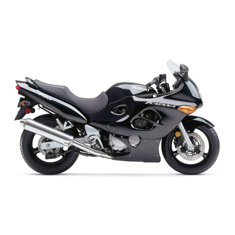
Suzuki VZR1800K6 User manual

Assembly and Pre-Delivery
Service Guide
K6
January ’06 Printed in Japan (TK) 03
99505-01096-03E
FOREWORD
This motorcycle has been designed and produced utilizing Suzuki’s most modern
technology. The finest product, however, cannot perform properly unless it is cor-
rectly assembled and serviced. This service guide has been produced to aid you in
properly assembling and servicing this motorcycle.
Please review this service guide carefully before performing any work. Take spe-
cial care to properly perform the required assembly and servicing marked by either
a Warning or a Caution. Failure to follow the directions in either of these two (2)
categories could lead to serious problems. # and
areas are denoted to emphasize certain areas and carry the following meanings:
#. . . . . . . Indicates a potential hazard that could result in
death or injury.
. . . . . . . . . . Indicates a potential hazard that could result in
motorcycle damage.
Any assembly and pre-delivery set-up performed on any Suzuki motorcycle by the
dealer shall be deemed by your Suzuki distributor to be performed at the dealer’s
sole risk and responsibility. The Suzuki distributor disclaims any and all liability,
obligation or responsibility for any defects resulting from said assembly and pre-
delivery set-up, and for any claims, demands or causes of action for damage to
property or for personal injuries resulting from the Dealer’s assembly and pre-
delivery set-up of Suzuki motorcycle.
This Assembly and Pre-Delivery Service Guide may contain photographs of
products sold in other markets. The assembly and pre-delivery service procedures
in this guide, however, apply to this market.
1
PREPARATION
WORKSHOP
#
A: Packed motorcycle
B: Working space
SELF PROTECTION
#
UNCRATING THE MOTORCYCLE
Remove the carton.
#
A: Crate
Remove the strap.
Take the front wheel assembly and handlebars assem-
bly off the crate base.
A: Strap
B: Front wheel assembly
C: Handlebars assembly
The workshop where the machine is assembled
should be clean, spacious, and have a level
floor.
The technician should wear protective clothing
such as leather gloves, a long sleeve shirt, eye
protection and safety shoes as shown in the
illustration when handling metal crates.
Metal crates may have sharp edges and may
cause injury.

2
Remove the bolts of the bracket.
A: Bolt
Remove the bolts from the crate.
A: Bolt
Lift the steel frame to separate it from the base of the
crate.
Carefully remove the various component parts pack-
aged around the motorcycle.
#
A: Steel frame
B: Crate base
Handling crates requires two operators.
Be careful not to scratch the motorcycle.

3
LOCATION OF PARTS
Check all the components which have been removed from the base of the crate.
Parts listed above are installed respectively into the positions as follows.
Item Part Name Q’ty Remarks
A
Handlebars assembly 1
Clamp 2
Allen bolt 4 8 × 35 mm
Plastic cap 4
OD:14.5
For handlebar
clamp bolt
Screw 1
5 × 35 mm
For throttle
assembly
Screw 1 5 × 30 mm
For left switch
Screw 1 5 × 45 mm
For left switch
Clutch lever cover 1
Strap 5 L:140
Plastic cap 2 OD:36.0
For handlebar end
BHolder 1 For front brake
master cylinder
Allen bolt 2 6 × 20 mm
CO-ring 1 For throttle cable
Strap 1 L:90
DFront fender 1
Stepped Allen bolt 4 6 × 16 mm
Item Part Name Q’ty Remarks
E Rear view mirror 2 Right and Left
F
Frame body cover 2 Right and Left
Frame body lower cover 1
Fastener 1 Large
Fastener 2 Medium
Tapping screw 2 5 × 16 mm
G Fastener 1 Small
HSeat tail cover 1
Hexagonal wrench 1 5 mm
I Front wheel spacer 1
J Front wheel assembly 1
K
Reflex reflector 2 Right and Left
Bracket 2 Right and Left
Flange nut 2 5 mm
Flange bolt 1 6 × 12 mm
LBattery electrolyte
container 1
M Owner’s manual 1
OD : Outside diameter (mm)
ID : Inside diameter (mm)
L : Length (mm)
T : Thickness (mm)
TL
OD ID
NOTE:
Please hand over the parts shown as Item H in the above table to your customer together with motor-
cycle.
JD EA H
IFK
G
FCK
EB

4
The photograph shown indicates the parts dismounted
from the motorcycle in addition to the items shown in
the preceding page.
A: Front brake master cylinder
B: Throttle assembly
C: Left switch
Clutch cable
AA
D
E
G
F
H
I
K
J
BB
L
MM
CC
D
E
F
G
H
I
J
KL

5
The certification of vehicle pre-delivery form must
be filled out in duplicate for every motorcycle.
Use of this form is mandatory and serves as pro-
tection for yourself and your customer, as well as
assuring that all necessary assembly and service
functions have been completed.
ASSEMBLY
REMOVING THE BRACKET
Remove the bolt to take off the front brake master cyl-
inder from the bracket.
A: Front brake master cylinder
B: Bolt
C: Bracket
Remove the bracket from the handlebar mounting
position.
A: Bracket
B: Bolt
HANDLEBARS
Loosen the throttle housing retaining screws.
Insert the throttle assembly onto the handlebars.
A: Throttle assembly
B: Handlebars
Keep the position of front brake master cylin-
der with its cap facing upwards until it is
installed.
NOTE:
The bolt is no longer needed and this may be
discarded.
Be careful not to scratch the fuel tank.
NOTE:
The bracket and bolts are no longer needed
and these may be discarded.

6
Install the handlebars assembly using the two clamps
and four bolts.
A: Clamp
B: 8 × 35 mm Allen bolt
C: Punch mark
D: Dot mark
E: Plastic cap OD:14.5 mm
Tighten the handlebar clamp bolts to the specified
torque.
"Handlebar clamp bolt:
23 N·m (2.3 kgf-m, 16.5 lb-ft)
After installing the handlebars, fit the plastic cap on the
head of each bolt.
A: 8 × 35 mm Allen bolt
B: 8 × 35 mm Allen bolt
C: Plastic cap OD:14.5 mm
#
A: Front brake hose
B: Throttle cables
C: Right switch wiring harness
D: Clutch cable
E: Left switch wiring harness
F: Tachometer lead wire
NOTE:
The punch mark on the clamps shows front
side.
Align the dot mark on the handlebars with the
mating surface of the front side of left clamp.
NOTE:
To install the handlebars correctly, first tighten
the bolt
Aof the front side with specified
torque and then tighten the bolt
Bof the rear
side.
Make sure that the clamp has no clearance at
the front side as shown in the illustration.
FORWARD
The line drawings on page 37, 38 and 39 show
the proper routing of the control cables, hose
and wirings.
Refer to them in addition to following the
instructions carefully.

7
THROTTLE
Insert the boss of the throttle housing into the hole on
the handlebars.
Tighten the throttle assembly with two screws.
#
A: Boss
B: Hole
C: 5 × 45 mm screw
D: 5 × 35 mm screw
FRONT BRAKE MASTER CYLINDER
Install the front brake master cylinder onto the handle-
bars.
Align the dot mark on the handlebars with the master
cylinder-to-holder fitting surface.
Tighten the master cylinder mounting bolts to the
specified torque.
"Front brake master cylinder mounting bolt:
10 N·m (1.0 kgf-m, 7.0 lb-ft)
A: Holder
B: Front brake master cylinder
C: 6 × 20 mm Allen bolt
D: 6 × 20 mm Allen bolt
E: Dot mark
A: Bolt
B: Holder
C: Front brake master cylinder
D: Handlebars
Check to ensure that the throttle operates
freely and closes automatically.
NOTE:
To install the holder correctly, first tighten the
bolt
Cof the upper side with specified torque
and then tighten the bolt
Dof the lower side.
NOTE:
Install the holder in position according to the
mark “UP”.
Make sure that the holder has no clearance at
the upper side as shown.
Check for brake fluid leakage.

8
Connect the front brake light switch lead wires coupler
to the brake light switch.
A: Front brake light switch
B: Lead wire coupler
LEFT SWITCH
Insert the boss of the left switch holder into the hole on
the handlebars.
Tighten the left switch assembly with the two screws.
A: Boss
B: Hole
C: 5 × 45 mm screw
D: 5 × 30 mm screw
Connect the clutch lever position switch lead wire cou-
pler to the switch.
A: Clutch lever position switch
B: Lead wire coupler
Be careful not to pinch the wiring harness
between the housing and holder.

9
CLUTCH CABLE
Pass the clutch cable through the lever cover.
A: Clutch cable
B: Clutch lever cover
Turn the clutch cable adjuster and lock nut in as far as
possible and align the slots.
Insert the inner cable end into the recess in the clutch
lever, then pull on the outer cable housing and insert it
into the adjuster.
Do not adjust at this time.
Adjustment will be covered in the SERVICING section.
Install the lever cover.
A: Clutch cable
B: Adjuster
C: Lock nut
D: Cable end
E: Clutch lever cover
RIGHT
CLAMP
Clamp the right handlebar switch wiring harness, front
brake hose union or front brake hoses with straps.
A: Strap L:140 mm
B: Right switch wiring harness
C: Front brake hose union
D: Front brake hose
NOTE:
Before installing the cable, grease the cable
end.
NOTE:
Cut the remaining of the strap as shown in the
photograph.
OUTSIDE
,

10
LEFT
Clamp the handlebar left switch wiring harness, clutch
cable and tachometer lead wire with strap.
A: Strap L:140 mm
B: Left switch wiring harness
C: Clutch cable
D: Tachometer lead wire
Clamp the throttle cable to the headlight stay with O-
ring.
A: Throttle cables
B: O-ring
C: Strap L:90 mm
D: Headlight stay
PLASTIC CAP
Install the plastic cap on the handlebars end.
A: Plastic cap OD:36.0 mm
Attach a hoist band, Pass the hoist band through the
handlebar as shown in the photograph.
A: Hoist band
B: Tachometer
NOTE:
Cut the remaining of the strap as shown in the
photograph.
OUTSIDE
OUTSIDE
NOTE:
Cut the remaining of the strap as shown in the
photograph.
Be careful dose not touch the hoist band and
tachometer.

11
Remove the crate axle bracket from the crate base.
A: Crate axle bracket
B: Bolt
1. Lift the front of motorcycle by using a hoist.
2. Raise the rear of motorcycle.
3. Pull the crate base forward, then balance the
motorcycle.
FRAME BODY COVER
Remove the seat using the key.
A: Seat lock
B: Seat
Remove the fastener.
A: Fastener
NOTE:
The bracket and bolts are no longer needed
and these may be discarded.
NOTE:
To remove the fastener, push in the center pin
and pull out the fastener.

12
Remove the screws.
Remove the frame covers.
A: Frame cover
B: Allen screw
C: Boss
D: Hook (Frame cover)
E: Rubber cushion (Fuel tank)
Remove the fuel tank fitting bolt.
Slide the fuel tank backward a little.
A: Fuel tank
B: Bolt
Remove the screws.
A: Frame body upper cover
B: Stepped Allen screw
Unhook the clicks.
Remove the frame body upper cover assembly.
A: Frame body upper cover
B: Frame body head cover
C: Click
FORWARD

13
RIGHT
Fix the frame body cover to the frame body upper
cover assembly with screw. (Right)
A: Frame body cover
B: Frame body upper cover
C: Guide
D: Hole
E: Hook
F: Click
G: 5 × 16 mm tapping screw
LEFT
Fix the frame body cover to the frame body upper
cover assembly with screw. (Left)
A: Frame body cover
B: Frame body upper cover
C: Guide
D: Hole
E: Hook
F: Click
G: 5 × 16 mm tapping screw
LEFT
Fit the frame body cover assembly (Left) to the frame
body lower cover.
A: Frame body lower cover
B: Frame body cover assembly (Left)
C: Guide
D: Hole
E: Boss
F: Hole (rubber cushion)
G: Hook
Fix the frame body cover assembly (Left) to the frame
body lower cover with fastener.
A: Fastener
B: Guide
C: Hook
NOTE:
To install the fastener, pull the center pin and
fix the fastener by pushing the center pin.

14
RIGHT
Fit the frame body cover assembly (Right) to the
frame body lower cover assembly.
A: Frame body lower cover assembly
B: Frame body cover assembly (Right)
C: Guide
D: Hole
E: Boss
F: Hole (rubber cushion)
G: Hook
Fix the frame body cover assembly (Right) to the
frame body lower cover assembly with fastener.
A: Fastener
B: Hook
Check the engine coolant and brake fluid level.
If the level is lower than the “LOW” level line, carry out
the SERVICING procedure.
A: Engine coolant reservoir
B: Rear brake master reservoir
C: Upper level line
D: Lower level line
Insert the breather hose to the hole.
A: Breather hose
B: Hole (Frame body lower cover)
NOTE:
To install the fastener, pull the center pin and
fix the fastener by pushing the center pin.
Be sure not to bend or twist the hose when
installing.

15
LEFT RIGHT
Install the recess of frame body lower cover to the
boss of frame.
A: Recess (Frame body lower cover)
B: Boss (Frame)
RIGHT
Install the fastener by pushing.
A: Fastener (Large)
B: Boss (Frame)
Install the frame body cover assembly.
Pass the throttle cable (Pulling) through over the boss
of frame body head cover.
A: Throttle cable (Pulling)
B: Throttle cable (Returning)
C: Clutch cable
D: Boss
Fit the frame body cover (Right and Left).
A: Frame body cover assembly
B: Click

16
Tighten the screws.
Install the fastener.
A: Stepped Allen screw
B: Fastener (Small)
Reinstall the fuel tank.
Reinstall the frame cover.
Reinstall the seat.
Insert the seat hook into the seat hook retainer and
push down the seat firmly.
A: Seat assembly
B: Seat hook
C: Seat hook retainer
FRONT FENDER
Remove the bolts.
A: 6 × 16 mm stepped Allen bolt
Install the front fender to the front fork legs with six
bolts.
A: Front fender
B: 6 × 16 mm stepped Allen bolt
C: Front fork
D: Bracket (Front brake hose)
NOTE:
To install the fastener, pull the center pin and
fix the fastener by pushing the center pin.

17
FRONT REAR
BRAKE DISC
To prevent brake squeaking and pad contamination,
carefully clean the front and rear brake disc plates with
alcohol or other non-petroleum based solvent.
This will remove the rust-preventive coating and dirt.
FRONT WHEEL
When installing the front wheel onto the axle, special
attention must be paid to the arrow of the rotational
direction on the tire sidewall.
When the tire is properly installed, the arrow must indi-
cate forward rotation of the wheel.
Loosen the axle clamp bolt.
Remove the front axle from the fork legs.
A: Axle clamp bolt
B: Front axle
Mount the front wheel assembly properly.
A: Right fork leg
B: Left fork leg
C: Front wheel spacer
D: Front axle
FRONT
FRONT

18
Temporarily remove the left front brake caliper.
A: Supporter
B: Brake caliper (Left)
C: Caliper mounting bolt
Remove the supporter from the brake pad of the right
front brake caliper.
A: Supporter
Attach the front wheel spacer to the front wheel hub.
Carefully insert the front brake disc plate between the
caliper brake pads.
A: Front wheel spacer
B: Oil seal (Lip)
C: Pads
D: Disc plate
Do not remove the supporter inserted between
the brake pads until the brake caliper is
installed.
When install the front wheel spacer, be careful
not to scratch the oil seal lip.

19
Insert the front axle from the right side of fork leg and
fix the front wheel assembly to the front fork.
A: Front axle
B: Oil seal (Lip)
Tighten the front axle to the specified torque.
"Front axle: 100 N·m (10.0 kgf-m, 72.5 lb-ft)
A: Front axle
Tighten the axle clamp bolt to the specified torque.
"Front axle clamp bolt:
23 N·m (2.3 kgf-m, 16.5 lb-ft)
A: Axle clamp bolt
When install the front axle, be careful not to
scratch the oil seal lip.
Never use force to install the front axle.
If it cannot be installed by hand, it is not cor-
rectly aligned.
Table of contents
Other Suzuki Motorcycle manuals

Suzuki
Suzuki LT-Z250 User manual

Suzuki
Suzuki GSX-1300R User manual

Suzuki
Suzuki RM250 Application guide

Suzuki
Suzuki GSF1250 User manual

Suzuki
Suzuki PE175 User manual

Suzuki
Suzuki GS1000G 1980 User manual

Suzuki
Suzuki GS700 Manual

Suzuki
Suzuki GSX 400F User manual

Suzuki
Suzuki GSX1400 User manual

Suzuki
Suzuki RV125K3 User guide

Suzuki
Suzuki SV1000K5 Manual

Suzuki
Suzuki GSX-R600 User manual

Suzuki
Suzuki DL1000 User manual

Suzuki
Suzuki 1989 GS500EK User manual

Suzuki
Suzuki DR350 User manual

Suzuki
Suzuki RMX450Z User manual

Suzuki
Suzuki AN650 User manual

Suzuki
Suzuki SFV650 User manual

Suzuki
Suzuki VL1500K7 Reference manual

Suzuki
Suzuki RG50 User manual