FAQs and Troubleshooting
Does my AV processor correct for the latency (time delay) of the wireless unit?
Yes, this will be reected in a longer than normal subwoofer distance, as shown under the
set-up section of the AV processor. An additional 25-28 feet (beyond the actual subwoofer
distance) is normal.
I keep hearing interference artifacts or experiencing signal drop-outs – how can I
correct for this?
Always try to keep a line-of-sight between the transmitter and receiver units with no hard
barriers or walls between them.
Avoid placing other 2.4 GHz devices near the units like wireless phones, mobile phones, Wi-
Fi routers, baby monitors, etc.
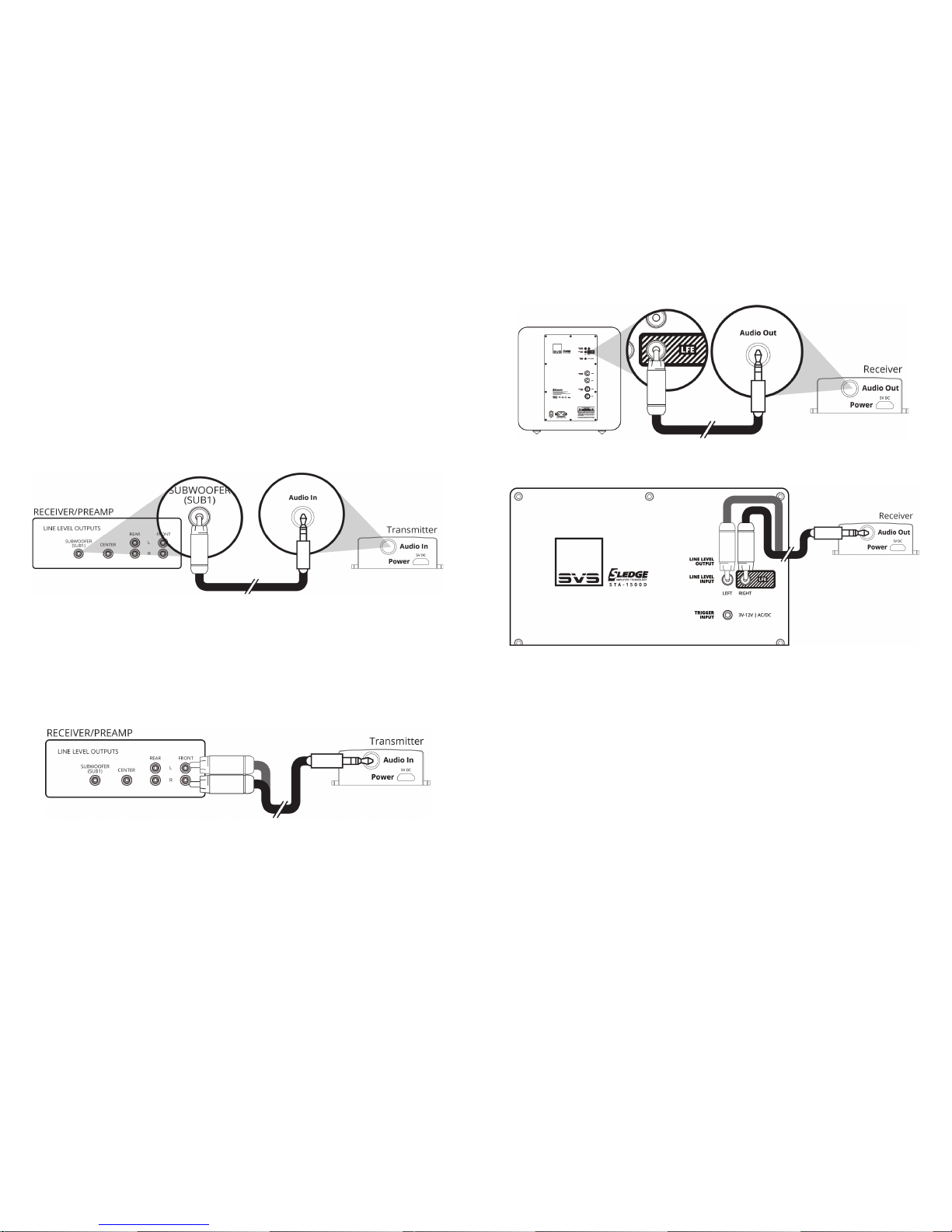
Can this unit be used for full-range loudspeaker applications?
Yes, the unit can support a full-range 2-channel stereo application. The loudspeakers will
need their own amplier. Connect the 3.5 mm to dual RCA adapter cable to the L/R line
level pre-outs of the 2-channel stereo source and to the input on the wireless transmitter.
Connect the 3.5 mm to dual RCA adapter cable to the L/R inputs of the loudspeaker
amplier and to the input on the wireless receiver. Connect the transmitter/receiver USB A
to Micro B cable and the 5 VDC power supply. Connect the speakers to the amplier with
conventional speaker wiring.
Warranty & Support
»5-YEAR UNCONDITIONAL WARRANTY
»SVS oers the industry’s most comprehensive warranty on all our products. SVS
warrants the SoundPath Wireless Subwoofer Kit and all products to be free from
defects in the workmanship for 5 years from date of purchase.
»This, and all the SVS customer Bill of Rights can be viewed online at:
www.svsound.com/bill-of-rights.
Share Your Thoughts
SVS Sound Experts are standing by Monday to Friday from 9AM-9PM ET, Saturday from
12PM-6PM, and Sunday from 12PM-4PM to assist you with set-up, optimization and any
questions you have about the SoundPath Wireless Subwoofer Kit. They can be reached by
phone, email or chat via the options below.
We also invite you to share a review on our website and to join our fun and active social
media community where we share reviews, featured systems, interesting audio articles and
more.
www.svsound.com | Facebook.com/svsound | Instagram.com/SVS_Sound | Twitter.com/SVS_Sound
Safety Instructions
»Read these instructions.
»Keep these instructions.
»Heed all warnings.
»Follow all instructions.
»Do not use this apparatus near water.
»Clean only with dry cloth.
»Install in accordance with the manufacturer’s instructions.
»Do not install near any heat sources such as radiators, heat registers, stoves, or
other apparatus (including ampliers) that produce heat.
»Do not defeat the safety purpose of any polarized or grounding-type plug. A
polarized plug has two blades with one wider than the other. A grounding type
plug has two prongs and a third grounding point. The wide blade or the third
prong are provided for your safety. If the provided plug does not t into your
outlet, consult an electrician for replacement of the obsolete outlet.
»Protect the power cord from being walked on or pinched particularly at plugs,
convenience receptacles, and the point where they exit from the apparatus.
»Only use attachments/accessories specied by the manufacturer.
»Unplug this apparatus during lightning storms or when unused for long periods
of time.
»Refer all servicing to qualied service personnel. Servicing is required when the
apparatus has been damaged in any way, such as power-supply cord or plug is
damaged, liquid has been spilled or objects have fallen into the apparatus, the
apparatus has been exposed to rain or moisture, does not operate normally, or
has been dropped.
»WARNING: To reduce the risk of re or electric shock, this apparatus should not
be exposed to rain or moisture and objects lled with liquids, such as vases,
should not be placed on this apparatus.
»To completely disconnect this equipment from the mains, disconnect the power
supply cord plug from the receptacle.
»The mains plug of the power supply cord shall remain readily operable.
The lightning ash with arrowhead symbol within an equilateral triangle
is intended to alert the user to the presence of uninsulated “dangerous
voltage” within the products enclosure that may be of sucient magnitude
to constitute risk of electric shock to persons.
The exclamation point within a triangle is intended to alert the user to the
presence of importance operating and maintenance {servicing) instructions
in the literature companying the product.
The equipment is a Class II or double insulated electrical appliance. It has
been designed in such a way that it does not require a safety connection to
electrical earth.