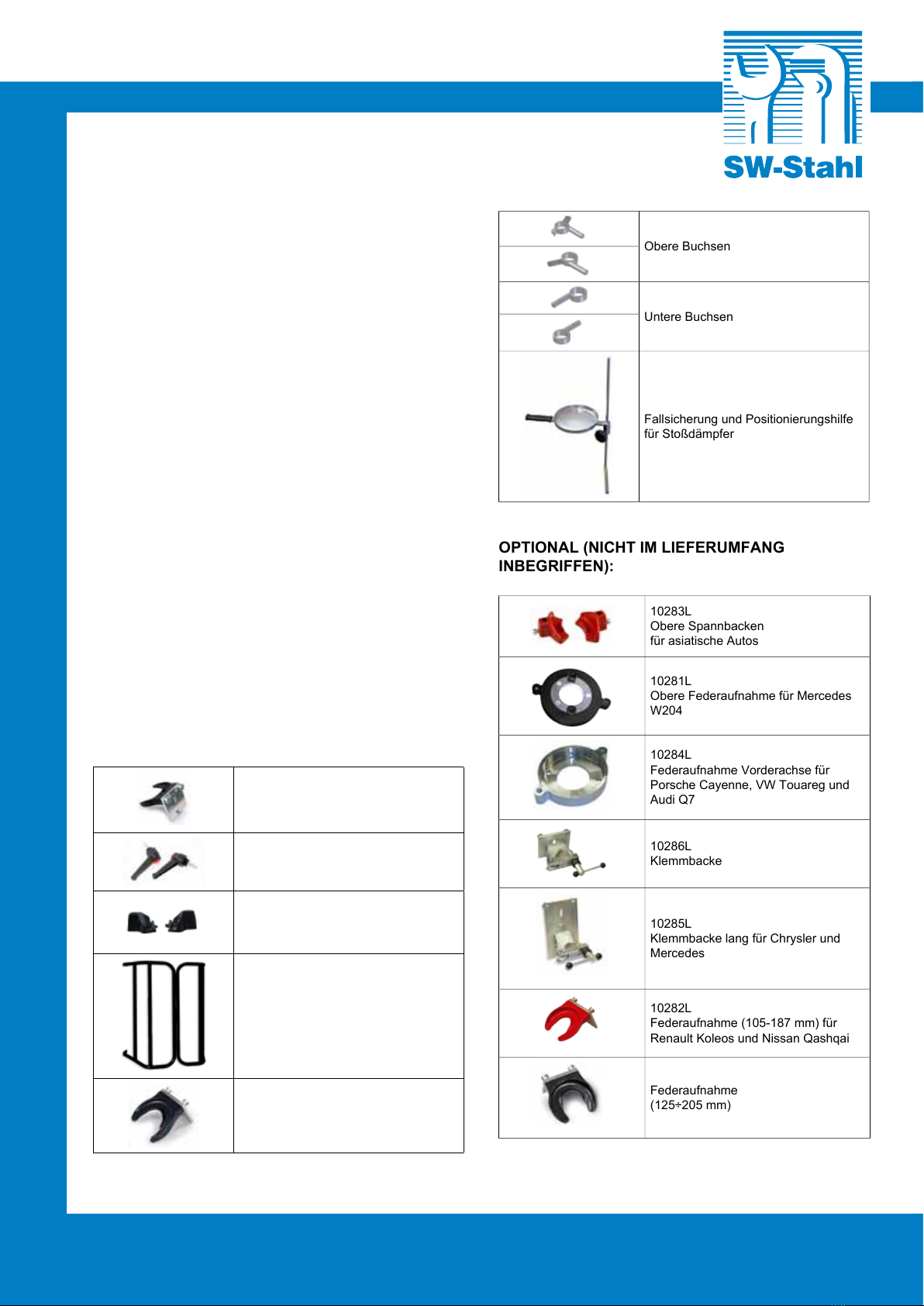
10278L
SW-Stahl GmbH
BEDIENUNGSANLEITUNG
7
nochmals kurzeitig Druckluft an, damit sich das Öl
gleichmaßig verteilen kann.
13. INSTANDHALTUNG
Regelmäßig (alle 2 Monaten oder 200 Betriebsabläufe)
die Führungssäulen von Ablagerungen (Staub,
Schmutz usw.) mit einem trockenem Tuch säubern.
VERWENDEN Sie NIEMALS Öl oder
reinigende Produkte um die Führungssäulen
zu reinigen.
14. REPARATUR
Eventuelle Reparaturen dürfen nur von Fachkräften
ausgeführt werden; wenden Sie sich für Reparaturen
und Originalersatzteile an Ihren Fachhändler.
15. ZUBEHÖR NICHT IM LIEFERUMFANG
15.1 Klemmbacke
15.2 Ausbau mit Klemmbacke
Die folgenden Anweisungen dienen lediglich als
Leitfaden für den Umgang mit dem Werkzeug.
Beachten Sie daher immer die Vorgaben und
Reparaturanweisungen des Fahrzeugherstellers!
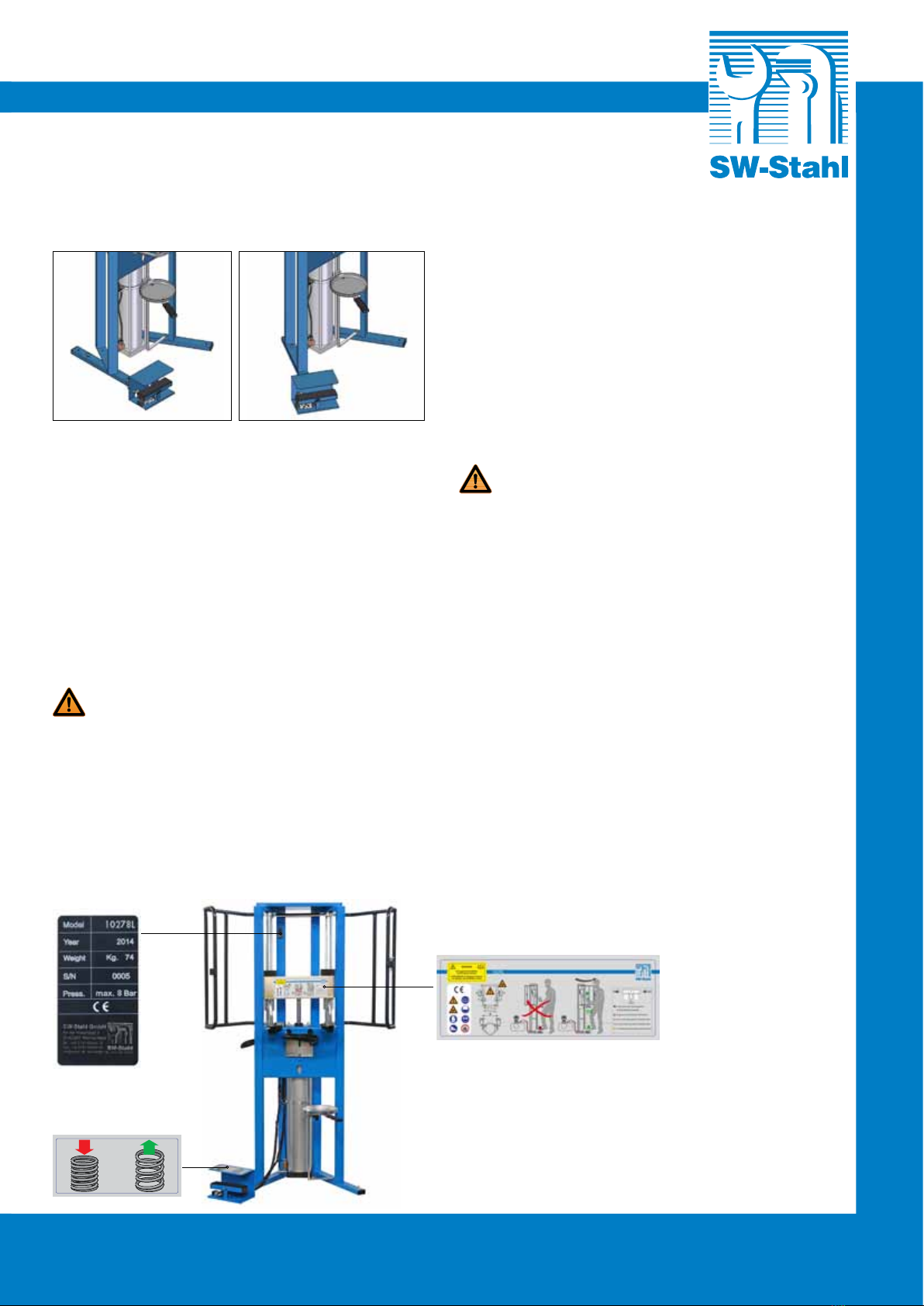
Um den Ausbau zu erleichtern, ist es angebracht, die
Befestigungsmutter auf dem Federbeinstützlager
zu lockern, bevor die Stoßdämpfer in die Maschine
10278L eingeführt werden. Den Stoßdämpfer
positionieren und das Stoßdämpferrohr fest in die
Klemmbacke einspannen, so dass der Stoßdämpfer
auf der Maschine zentriert ist (Abb. 5).
Die schwenkbaren Arme der Feder nähern und
anschließend die oberen Spannbacken auf der ersten
benutzbare Federwindung ansetzen.
Nach der genauen Positionierung der oberen
Spannbacken sind die schwenkbaren Arme (Abb. 4)
durch Anziehen der Arretierhebel auf der Rückseite
des Gehäuses zu blockieren.
Mit dem Fußdruckluftschalter die Feder so weit
spannen, dass der Druck, den die Feder auf das
Federbeinstützlager ausübt, gerade aufgehoben wird.
Die Feder nicht bis auf Block spannen.
Die Mutter des Federbeinstützlagers abschrauben und
das Federbeinstützlager entfernen.
Die Feder entspannen und alle verschlissenen und
defekten Bauteile austauschen.
15.3 Einbau mit Klemmbacke
Alle Arbeitsschritte in umgekehrter Reihenfolge
ausführen.DieEinbaupositiondesneuenStoßdämpfers
muss identisch mit dem alten Stoßdämpfer sein.
Das Federbeinstützlager auf der Kolbenstange
aufsetzen und mit einer neuen Befestigungsmutter
verschrauben.
Den Fußdruckluftschalter betätigen, bis die Feder an
dem Federbeinstützlager anliegt.
Der Stoßdämpfer ist jetzt montiert; mit dem
Fußdruckluftschalter die Feder vollständig entspannen,
die Arme nach außen schwenken und den so
zusammengebauten Stoßdämpfer aus der Maschine
10278L entfernen.
16. SCHMIERUNG DER VORRICHTUNG
Für dieses Gerät immer eine Druckluft-Wartungseinheit
auf in der Leitung verwenden. Es wird empfohlen
eine Wartungseinheit aus Öler-, Druckminderer- und
6
5