manuals.online logo
Brands
  1. Home
  2. •
  3. Brands
  4. •
  5. Swann
  6. •
  7. IP Camera
  8. •
  9. Swann SWPRO-1080PTZ User manual

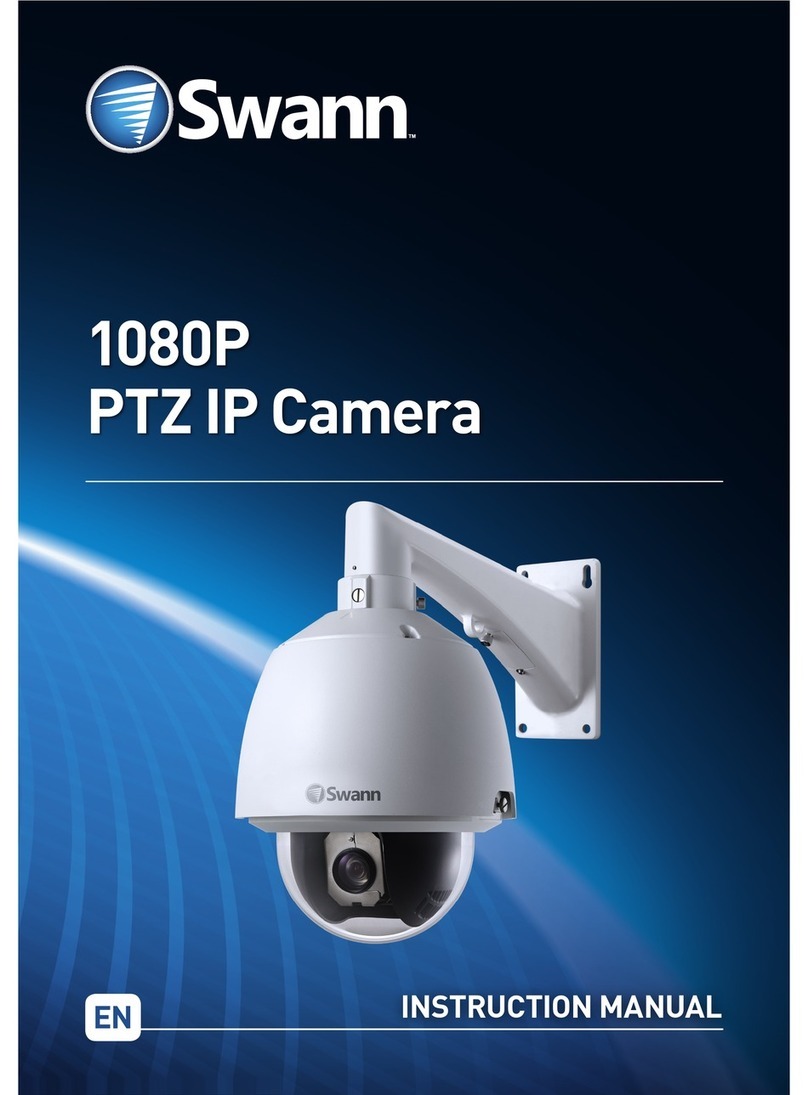
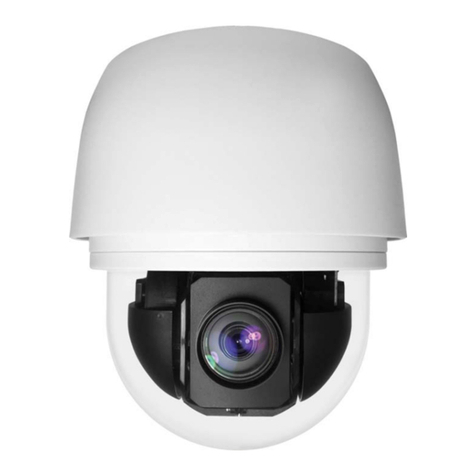
Swann SWPRO-1080PTZ User manual

Pan-Tilt-Zoom
Security Camera
For use with Swann Pro-Series 1080p DVRs
EN INSTRUCTION MANUAL
Security Made Smarter
M1080PTZVER1E | © Swann 2017
Step One - Introduction
Important instructions
1. Make sure the camera is securely fastened.
2. Do not operate if wires and terminals are exposed.
3. Only use the supplied power adapter (24V).
4. Do not manually move the camera when it is turned
on as this may damage the internal mechanism.
5. Use a small Phillips-head screwdriver to connect
the red and black PTZ wires on the camera, to the
PTZ connection on the video & power cable.
6. This camera is compatible with most Swann Pro-
Series 1080p DVRs.
Important note: All jurisdictions have specific laws
relating to the use of cameras. Before using any cam-
era for any purpose, it is the buyer’s responsibility to
be aware of all applicable laws and regulations that
prohibit or limit the use of cameras.
VGA 12V INVIDEO IN
AUDIO
OUT LAN&USB
7
8
5
6
3
4
1
2
AUDIO IN
B A
PTZ
If your DVR has a green PTZ connection (as shown
above), go to step two for instructions.
If your DVR has a green and orange PTZ connection
(as shown above), go to step three for instructions.
LANLAN
VGAVGA
7531
8 6 4 2
AUDIO
OUTPUT
AUDIO
OUTPUT
AUDIO
INPUT
AUDIO
INPUT
3 1
4 2
12V12V
RS485RS485
VIDEO INPUTVIDEO INPUT
The camera has an on-screen display that can
be accessed using the PTZ controls on your DVR.
For an explanation about the functions available,
download the instruction manual from support.
swann.com. Search for – 1080 PTZ OSD Manual.
Step Two - Connecting the Camera
Power Input
Video Output
1
Red
Black
21
3
Power Adapter
4
Power Input
Video Output
Video Input
Power Output
PTZ
Video & Power Cable
PTZ
VGA 12V INVIDEO IN
AUDIO
OUT LAN&USB
7
8
5
6
3
4
1
2
AUDIO IN
B A
PTZ
2 3
Red
Black
Step Two - Connecting the Camera
1. Using a small Phillips-head screwdriver, attach the
PTZ wires (red & black) on the camera, to the PTZ
connection on the video & power cable. Ensure the
wires are held firmly then tighten (don’t use too much
force). Connect the video output and power input on
the camera to the corresponding connections on the
video & power cable.
2. Connect the video output on the video & power ca-
ble to a spare video input on your DVR.
3. Disconnect the PTZ module on your DVR. Using a
flat-head screwdriver, attach the PTZ wires (red &
black) to the PTZ module. The red cable connects
to “A” and the black cable connects to “B” (as illus-
trated). Ensure the wires are held firmly then tighten
(don’t use too much force). Reconnect the PTZ mod-
ule to your DVR when finished.
4. Connect the power input on the video & power ca-
ble to the provided power adapter. Connect the power
adapter to a spare power outlet.
5. The camera will initialise a self-test when turned
on then display information about itself on-screen:
S/N: 201705090001
VERSION : V1.36AN
MODEL : DOME
PROTOCOL : PELCO
DOME ID : 001
BAUDRATE : 9600
Your DVR’s default PTZ settings should allow you to
use the camera without any configuration. Go to step
four for instructions on how to control your camera
and how to mount the camera onto a flat surface.
Step Three - Connecting the Camera
Power Input
Video Output
1
21
3
Power Adapter
4
Power Input
Video Output
Video Input
Power Output
PTZ
Video & Power Cable
PTZ
3
Red
Black
LANLAN
VGAVGA
7531
8 6 4 2
AUDIO
OUTPUT
AUDIO
OUTPUT
AUDIO
INPUT
AUDIO
INPUT
3 1
4 2
12V12V
RS485RS485
VIDEO INPUTVIDEO INPUT
2
Step Three - Connecting the Camera
1. Using a small Phillips-head screwdriver, attach the
PTZ wires (red & black) on the camera, to the PTZ
connection on the video & power cable. Ensure the
wires are held firmly then tighten (don’t use too much
force). Connect the video output and power input on
the camera to the corresponding connections on the
video & power cable.
2. Connect the video output on the video & power ca-
ble to a spare video input on your DVR.
3. Push the PTZ wires directly into the RS485 port
on your DVR. The red wire goes into the positive (+)
port and the black wire goes into the negative (-) port.
When pushing each wire into the port, the orange tab
above the port will push inward slightly. To remove
the wire, use a flat-head screwdriver to push the or-
ange tab inward then pull the wire.
4. Connect the power input on the video & power ca-
ble to the provided power adapter. Connect the power
adapter to a spare power outlet.
5. The camera will initialise a self-test when turned
on then display information about itself on-screen:
S/N: 201705090001
VERSION : V1.36AN
MODEL : DOME
PROTOCOL : PELCO
DOME ID : 001
BAUDRATE : 9600
Your DVR’s default PTZ settings should allow you to
use the camera without any configuration. Go to step
four for instructions on how to control your camera
and how to mount the camera onto a flat surface.
Step Four - Mounting & Controlling the Camera
The camera can be mounted onto a flat surface using
the pre-installed mounting bracket. Materials such
as hardwood, brick or concrete are good options, and
we’ve included all the gear you’ll need for mounting.
1. Position the camera in the location you want to
mount it. Make sure the location is rigid to prevent
vibration.
2. Using a pencil or felt tip maker, mark the four
screw holes on the surface to position the screws.
3. Using the appropriate screws for the surface you’re
fixing the camera to, screw the camera into place.
Make sure the camera’s bracket is aligned straight,
otherwise the image on the DVR will appear on an
angle.
4. For wooden surfaces, screw the camera directly
to the surface. For masonry surfaces (bricks or con-
crete) you’ll need to use the wall plugs.
To control the camera, use the mouse and click the
channel the camera is connected to. Click the “PTZ”
button on the camera toolbar (your DVR may differ
from the screenshot shown below).
1
23
1. Click the directional buttons to move the camera in
the direction selected.
2. This determines how fast the camera will move.
3. The ability to zoom into an object and to control the
level of focus. Press the Iris “+” button to access the
on-screen display.
Step Five - Installing the Ceiling Mount
1. The ceiling mount kit consists of three parts –
the ceiling mount, the cylinder pipe and the cam-
era mount. To use this, you need to remove the
wall mount first. Use a Phillips-head screwdriver
to remove the wall mount from the camera (three
screws in total). Gently pull the camera cable along
the wall mount to remove.
2. Now you’re ready to dismantle the ceiling mount.
Unscrew the ceiling mount counter-clockwise from
the cylinder pipe (the ceiling mount has an indent
where the camera cable can be placed). To remove
the camera mount from the cylinder pipe, unscrew
each screw located on the cylinder pipe until you
can remove the mount.
3. Drill a hole in the ceiling at the location you want
to mount it then mark the mounting holes on the
surface to position the screws (make sure the loca-
tion is rigid to prevent vibration). Using the appro-
priate screws for the surface you are mounting to,
secure the ceiling mount in place.
4. Screw the cylinder pipe counter-clockwise to the
ceiling mount and ensure the connection is secure.
5. Feed the cable through the top of the camera
mount (put the video connection through first
then the power and PTZ connections) then secure
the camera mount to the camera using the three
screws. Make sure the rubber seal is sitting flush
within the groove of the camera casing.
6. Feed the camera cable through the cylinder pipe
and ceiling mount and connect it to the provided vid-
eo & power cable.
7. Place the top of the camera mount into the cylin-
der pipe then fasten each screw to secure the cam-
era in place.
Other Swann IP Camera manuals

Swann Bolt HD 1080p User manual

Swann

Swann Bolt HD 1080p User manual

Swann 130dcm User manual

Swann

Swann 130dcm User manual

Swann 1080P PTZ IP Camera User manual

Swann

Swann 1080P PTZ IP Camera User manual

Swann A851 Pro-Series User manual

Swann

Swann A851 Pro-Series User manual

Swann SwannCloud User manual

Swann

Swann SwannCloud User manual

Swann 1080p SDI User manual

Swann

Swann 1080p SDI User manual

Swann Varifocal IP Camera User manual

Swann

Swann Varifocal IP Camera User manual

Swann SwannEye User manual

Swann

Swann SwannEye User manual

Swann SwannEye HD User manual

Swann

Swann SwannEye HD User manual

Popular IP Camera manuals by other brands

ACTi CAM-7300 series Hardware user manual

ACTi

ACTi CAM-7300 series Hardware user manual

NETWEEN CUBE Quick install guide

NETWEEN

NETWEEN CUBE Quick install guide

Ganz Thermal Series user manual

Ganz

Ganz Thermal Series user manual

Marshall Amplification CV340 Series Operation guide

Marshall Amplification

Marshall Amplification CV340 Series Operation guide

Atlantis V800-45W Multilanguage manual

Atlantis

Atlantis V800-45W Multilanguage manual

GeoVision GV-MFD120 quick start guide

GeoVision

GeoVision GV-MFD120 quick start guide

Axis M3026-VE user manual

Axis

Axis M3026-VE user manual

Foscam FI8919W user manual

Foscam

Foscam FI8919W user manual

TRENDnet TV-IP121WN Quick installation guide

TRENDnet

TRENDnet TV-IP121WN Quick installation guide

ICI FM 384 P Series user manual

ICI

ICI FM 384 P Series user manual

Omcon OMC-935IPBMEGA user manual

Omcon

Omcon OMC-935IPBMEGA user manual

KanDao Meeting Pro user guide

KanDao

KanDao Meeting Pro user guide

iMege M2210 Series user manual

iMege

iMege M2210 Series user manual

Huawei IPE Series installation guide

Huawei

Huawei IPE Series installation guide

MicroNet SP5319 Quick installation guide

MicroNet

MicroNet SP5319 Quick installation guide

Salora CDC100 quick start guide

Salora

Salora CDC100 quick start guide

Amcrest IP3M-HX2 quick start guide

Amcrest

Amcrest IP3M-HX2 quick start guide

Lorex VANTAGE LBC6050 Series quick start guide

Lorex

Lorex VANTAGE LBC6050 Series quick start guide

manuals.online logo
manuals.online logoBrands
  • About & Mission
  • Contact us
  • Privacy Policy
  • Terms and Conditions

Copyright 2025 Manuals.Online. All Rights Reserved.