Swing-N-Slide PB 8140 User manual

";;35681=2:Up to 6
!6:)>2-;:2
23
' x
29
'
'2?69
11
'W x
12
'L x 10'H
>?@6816:4(6924-6 hrs.
$
Swing•N•Slide • 1212 Barberry Drive • Janesville, Wisconsin 53545
Visit our web site at: www.swing-n-slide.com or call us at
''! ,"'(&)(#"'
(;=246>?2=D;@=<=;1@0?A6>6?
5??<BBB>B6:4:>86120;9
Other benefits include information on product warranties, assembly plan updates, joining our mailing
list for new products and promotions, receiving our newsletter, and providing feedback on products.
!$#&("(
PLEASE READ BEFORE BEGINNING ASSE BLY!!
Please make sure all lumber, hardware and accessory parts are accounted for. If you are missing
anything, please #"#(&()&" to the store where purchased. Please call our Customer
Service Department at the number below.
!WARNING:
Assembly by an adult.

2
Installat on Safety – Have You:
Consulted the assembly instructions supplied with your particular model?
Noted this accessory is to be used only on Swing•N•Slide approved designs? (Do not alter its design or add/remove components.)
Made sure all hardware is tightened securely? (Supplied bolt covers must also be astened securely.)
Using a hacksaw, cut o all protruding threaded ends o bolts and other asteners and remove any sharp edges with
a metal ile as needed, and coated astener ends with lead ree paint?
Placed the equipment on level ground, not less than six eet (1.8 meters) rom any structure or obstruction such as a ence, garage,
house, overhanging branches, laundry lines, or electrical wires?
Made sure home playground equipment is not installed over concrete, asphalt, packed earth or any other hard sur ace? (A all onto
a hard sur ace can result in serious injury to the equipment user.)
Veri ied that suspended climbing ropes, chain,or cable are securely anchored at both ends and cannot be looped back unpon itsel ?
Consulted in assembly instructions o your particular model or minimum use zones?
Used a water sealant on your play set to protect the wood and prevent cracking and warping?
Followed all anchoring and shock absorbing sur acing requirements on the back o this sheet as they apply?
Made sure not to allow children to use equipment until it is properly installed?
Made sure to adjust all swings so there is a minimum 8'' clearance between the swing and the ground sur ace?
Operat ng Safety – Have You:
Determined that on-site adult supervision is provided or children o all ages?
Warned children the ollowing be ore allowing them to use the equipment?
Not to walk close to, in ront o , behind or between moving items.
Not to twist swing or any other accessory chains or ropes or loop them over the top support bar since this will reduce the
strength o chain or rope.
Not to swing empty seats or other accessories.
Not to slide down swing chains.
Be sure to sit in the center o the swing seat and other accessories with ull weight on the seat.
Not to attach items to the playground equipment that are not speci ically designed or use with the equipment such as but not
limited to, jump ropes, clotheslines, pet leashes, cables and chain. They may cause a strangulation hazard.
Not to climb or walk on the top o swing beams, railings or roo .
Not to use equipment in a manner other than intended.
Not to get o equipment while it is in motion.
Not to climb on the equipment when it is wet.
Be sure to go down slides eet irst.
Determined that only one child per planned occupant seat should be allowed on this set at one time.
Determined children must be dressed appropriately or play. Avoid hooded jackets, bicycle or other sports helmets, clothing with
draw strings and loose itting clothes which could become entangled or snagged on equipment.
Determined that suspended climbing ropes, chain, or cable are securely anchored at both ends and cannot be looped back upon
itsel .
Made certain the slide is placed so that is is not in direct sunlight.
Safety Ma ntenance – Follow these preventive maintenance instructions at the intervals required:
To prevent the deterioration o materials, remove plastic swing seats and other plastic accessories when outdoors temp dips down to
or below 32° F and take indoors. Reinstall these plastic elements at the beginning o each play season.
At the beginning o each play season check metal parts or rust. I ound, sand and repaint using a non led-based paint meeting the
requirements o 16 CFR 1303 or SOR/2005-109.
At the beginning o each play season and once a month during each play season, check all moving parts or wear, rust or other
deterioration. Replace as needed. I any o these conditions exist, call 1-800-888-1232 to order replacement accessories.
At the beginning o each play season and once a month during each play season lubricate metallic moving parts.
At the beginning o each play season and twice a month during each play season, check all protective coverings on bolts, pipes,
edges, and corners. Replace i they are loose, cracked, or missing.
At the beginning o each play season and twice a month during each play season, rake and check depth o loose ill protective
sur acing material to prevent compaction and maintain appropriate depth. Replace as necessary.
At the beginning o each play season and twice a month during each play season tighten all hardware.
At the beginning o each play season and twice a month during each play, check all wood members or deterioration and splinters.
Sand down splinters and replace deteriorating wood members.
D sposal Instruct ons
When the equipment is taken out o service, it must be disassembled and disposed o in such a way that no unreasonable hazards will exist at
the time the set is discarded.
Important! Add t onal Safety Instruct ons for all Sw ng-N-Sl de Playground Equ pment.
Save th s nstruct on sheet n the event the manufacturer needs to be contacted.
Observ ng the follow ng statements and warn ngs reduces the l kel hood of ser ous or fatal njury
Safety Checkl st for Sw ng-N-Sl de Play Sets and Accessor es

3
This product is intended for single family home/residential use only and not intended for use in any public setting.
Placement in any public setting constitutes a misuse of this product.
IMPORTANT!
ADDITIONAL REQUIRED SAFETY INSTALLATION INSTRUCTIONS
According to ASTM requirements, all kits must be anchored to the ground and, i the unit has a climbing rope, the rope end must be anchored to the ground. I soil conditions
permit stakes to be pulled out easily, cementing into ground is necessary.
• To anchor the un t to the ground, Follow the instructions included in this plan or applying Anchor-It devices to your unit, or use 2" x 4" x 18" (45mm x 95mm x 457mm) pressure-
treated stakes. Pound stakes into ground at least 12" (305mm) at all inside corners o the posts (including A- rame legs and climbing unit posts). Attach with our (4) 16D (3-1/2")
galvanized nails per stake into each tower and/or A- rame upright.
• If the un t has a cl mb ng rope, securely anchor the rope at both ends.
• Once the un t s completely assembled and before ch ldren are allowed to play on t, proper shock-absorb ng surfac ng mater al must be nstalled. This may be accomplished by
using loose- ill materials at a su icient depth. The Consumer Product Sa ety Commission “Handbook or Public Playground Sa ety” lists the ollowing materials and required
depths that are su icient or home/residential application. Supplemental in ormation may be ound in ASTM F1292. For all height protection up to 9 t. (2.742m) [recommended
or Swing•N•Slide kits]:
LOOSE FILL MATERIAL REQUIRED (UNCOMPRESSED) DEPTH1in. (mm)
Wood Mulch 9" (229mm)
Double Shredded Bark Mulch 9" (229mm)
Uni orm Wood Chips 12" (305mm)
These depths were der ved from the CPSC Handbook. Sw ng•N•Sl de has not done ndependent tests to determ ne these requ red depths.
When properly installed, shock absorbing material will completely cover the horizontal baseboards on climbing units. This protective sur acing must extend a m n mum o 6 t.
(1.828m) in all directions rom the perimeter o the equipment or rom the outermost edges o any component. For example, a slide extending beyond the plat orm must have
protective sur acing at least 6 t. (1.828mm) out rom both sides as well as the end. For swings, the protective sur ace must extend at least 14 ft. (6m) out rom both the back and
ront o the swing when the swing is in its rest position.
Swin -N-Slide® MANUFACTURERS LIMITED WARRANTY
Swing-N-Slide® takes great pride in the quality and durability of our products. Our Manufacturer’s Limited Warranty provides confidence and demonstrates our commitment
to providing quality residential playground products.
MANUFACTURER’S LIFETIME LIMITED WARRANTY
Swing-N-Slide® warrants its thermoformed slides and climbing mountains to be free from defects in workmanship and materials, under normal use and conditions, for the
lifetime of the product.
MANUFACTURER’S 5 YEAR LIMITED WARRANTY
Swin -N-Slide® warrants its Custom Ready-to-Build Play Set kits and accessories to be free from defects in workmanship and materials, under normal use and conditions,
for a period of 5 years.
MANUFACTURER’S 5 YEAR LIMITED WARRANTY
Swin -N-Slide® warrants its No-Cut and Wood Complete Ready-to-Assemble Play Set kits against wood rot and termite damage, and to be free from defects in
workmanship and materials, under normal use and conditions, for a period of 5 years for structural wood components.
Cosmetic defects that do not affect the structural integrity of the product, or natural defects of wood such as warping, splitting, checking, twisting, shrinkage, swelling or
any other physical properties of wood that do not present a safety hazard, are not covered by this warranty.
MANUFACTURER’S ONE YEAR WARRANTY
Swin -N-Slide® warrants its canopy roofs and/or tarps, and Timber GLOVE lumber wrap to be free from defects in workmanship and materials, under normal use and
conditions, for a period of one year.
Swin -N-Slide® will repair, or at its discretion, replace any part within the stated warranty period which is defective in workmanship or materials. This decision is subject
to verification of the defect upon delivery of the defective part to Swing-N-Slide® at 1212 Barberry Drive, Janesville, Wisconsin, 53545. Any part(s) returned to Swing-N-
Slide® must have prior approved Return Authorization Number and proof of purchase, including the date of purchase. This warranty is valid only if the product is used for
the purpose for which it was designed and installed at a residential, single family dwelling. This warranty is void if the product is put to commercial or institutional use. This
warranty does not cover (a) products which have been damaged by acts of Nature, negligence, misuse, or accident, or which have been modified or repaired by
unauthorized persons; (b) the cost of labor; or the cost of shipping the product, any part, or any replacement product or part.
Swin -N-Slide® DISCLAIMS ALL OTHER REPRESENTATIONS AND WARRANTIES OF ANY KIND, EXPRESS, IMPLIED, STATUTORY OR OTHERWISE, INCLUDING THE
IMPLIED WARRANTIES OF MERCHANTIBILITY AND FITNESS FOR A PARTICULAR PURPOSE. Swing-N-Slide® WILL NOT BE LIABLE FOR ANY INCIDENTAL OR
CONSE UENTIAL DAMAGES. This warranty is non-transferable and does not extend to the owners of the product subsequent to the original purchaser. Some states do not
allow limitations on implied warranties or exclusion of incidental or consequential damages, so these restrictions may not be applicable to you. This warranty gives you
specific legal rights. You may also have other rights, which vary from state to state.
This warranty also does not apply to:
• Structures not erected, maintained or inspected in conformance with Swin -N-Slide® installation plans
• Structures that have had parts added or substituted not in conformance with Swin -N-Slide® installation plans
•Parts that have been modified, altered or misused
•Parts that have not been used as designed or intended
•Damage due to acts of Nature, vandalism, abnormal use or abuse as determined by Swin -N-Slide®
;=3@=?52=6:3;=9.?6;:;:<8.D4=;@:1>.32?D the Consumer Product Safety Commission
(CPSC) publishes the Outdoor Home Playground Safety Handbook which can be downloaded for free
from BBB0<>04;A. An additional resource is the American Society of Testing and aterials (AST )
Standard Consumer Safety Performance Specification for Home Playground Equipment (AST F1148)
which can be purchased and downloaded from BBB.>?9;=4.

TOOLS REQUIRED • HERRAMIENTAS REQUERIDAS • OUTILS REQUIS
(&& '#(+&"
!!&
($!')& '(, '''
)'(!' $ $'( &$"(&''%)&
TOOLS REQUIRED
T30 Torx® Bit
T20 Torx® Bit
4
1/2'' Panhead Screw
11/4'' Wood Screw
2'' Wood Screw
2-1/2'' Wood Screw
1-1/4'' Lag Screw
2'' Lag Screw
1-1/2'' Lag Bolt
Tarp Washer
1/4'' Flat Washer
5/16'' Flat Washer
13/4'' Panhead Screw
3/4'' Pan Head Screw
1'' Truss Screw
3-1/2'' Hex Head Bolt
& (
5/16'T-Nut

PB 8140
Plan
Plan
Anchor-It Straps
Anchor-Its
5
Playful Chalet Tarp Chalk Board
(4) Shelf-Loc
(1) LH Split Beam brac et (1) RH Split Beam brac et
(6) Wrap-Loc
(2) 3X3 TO 4X4
Shelf-Loc
Abrazaderas EZ Frame

6
Assembly Instructions
Swing Hangers
Slotted Beam Clamp
Coolwave Slide
250 lb Weight Limit
THIS PRODUCT IS
INTENDED FOR USE
BY CHILDREN FROM
AGES 2-10 YEARS
For Home / Residential
Use ONLY
1212 Barberry Drive
Janesville, WI 53545
1-800-888-1232
www.swing-n-slide.com
R
ID Tag
Swing Seat
B2645?8696? 115 lbs.
Seats
V-hangers 22'' Uncoated Chain
58'' Coated Chain
Ring-Trap Combo
Combinación de anillos/sujetador
Step Brackets
";?2 (1 Left, 1 Right)
Safety Handle
13-3/4'' etal Rungs

7
Assembly Instructions
;.=1 6>?
(1) 1'' x 4'' x 11-3/8'' [PF 3611]
(2) 1-1/2'' x 4'' x 20'' [PF 3595]
(1) 1'' x 4'' x 11-5/8'' [PF 3612]
(1) 1'' x 4'' x 12-3/4'' [PF 3613]
(2) 1'' x 4'' x 13-1/2'' [PF 3614]
(2) 1'' x 4'' x 15-3/8'' [PF 3615]
(2) 1'' x 4'' x 17-3/8'' [PF 3616]
(4) 1'' x 4'' x 23-1/2'' [PF 3617]
(2) 1'' x 4'' x 28-1/2'' [PF 3618]
(9) 1'' x 4'' x 30'' [PF 3619]
(11) 1'' x 4'' x 30'' [PF 3620]
(4) 1'' x 4'' x 30'' [PF 3621]
(1) 1'' x 4'' x 41-1/2'' [PF 3622]
(6) 1'' x 4'' x 47-1/2'' [PF 3623]
(1) 1'' x 4'' x 47-1/2'' [PF 3624]
(2) 1'' x 5'' x 30'' [PF 3625]
(1) 1'' x 5'' x 47-1/2'' [PF 3626]
(2) 1'' x 6'' x 12'' [PF 3627]
(1) 1'' x 4'' x 20'' [PF 3628]
(2) 5/4'' x 4'' x 24'' [PF 3629]
(2) 5/4'' x 4'' x 27'' [PF 3630]
(1) 5/4'' x 4'' x 47'' [PF 3631]
(3) 5/4'' x 4'' x 47-1/2'' [PF 3632]
[PF 3611]
(
[PF 3612]
(
(2) 1-1/2'' x 3'' x 47-1/4'' [PF 3633]
(2) 1-1/2'' x 3'' x 94'' [PF 3634]
(1) 2'' x 4'' x 3-1/2'' [PF 3635]
(1) 2'' x 4'' x 17-1/4'' [PF 3419]
(3) 2'' x 4'' x 47-1/2'' [PF 3404]
(2) 3'' x 3'' x 94'' [PF 3636]
(1) 4'' x 4'' x 47-1/2'' [PF 3405]
(3) 4'' x 4'' x 96'' [PF 3636]
English(*) Metric(Cm) English(*) Metric(Cm)
1x4 2.5x7.6 5/8x3-3/8 1.59x8.57
1x5 2.5x12.7 5/8x4-1/2 1.59x11.43
5/4x4 3.2x10.2 1x3-1/2 2.5x8.89
5/4x6 3.2x15.3 1x5-1/2 2.5x14
2x2 5x5 1-1/2x1-1/2 3.8x3.8
2x3 5x7.6 1-1/2x2-1/2 3.8x6.4
2x4 5x10 1-1/2x3-1/2 3.8x9
2x6 5x15.3 1-1/2x5-1/2 3.8x14
3x3 7.6x7.6
4x4 10x10 3-1/2x3-1/2 9x9
(*) Estim ated Sizing Due to Cutting Process
NO M IN AL M ATER IAL SIZE
LISTED SIZE
TRUE SIZE
7.6x7.6
3x3
8
Assembly Instructions
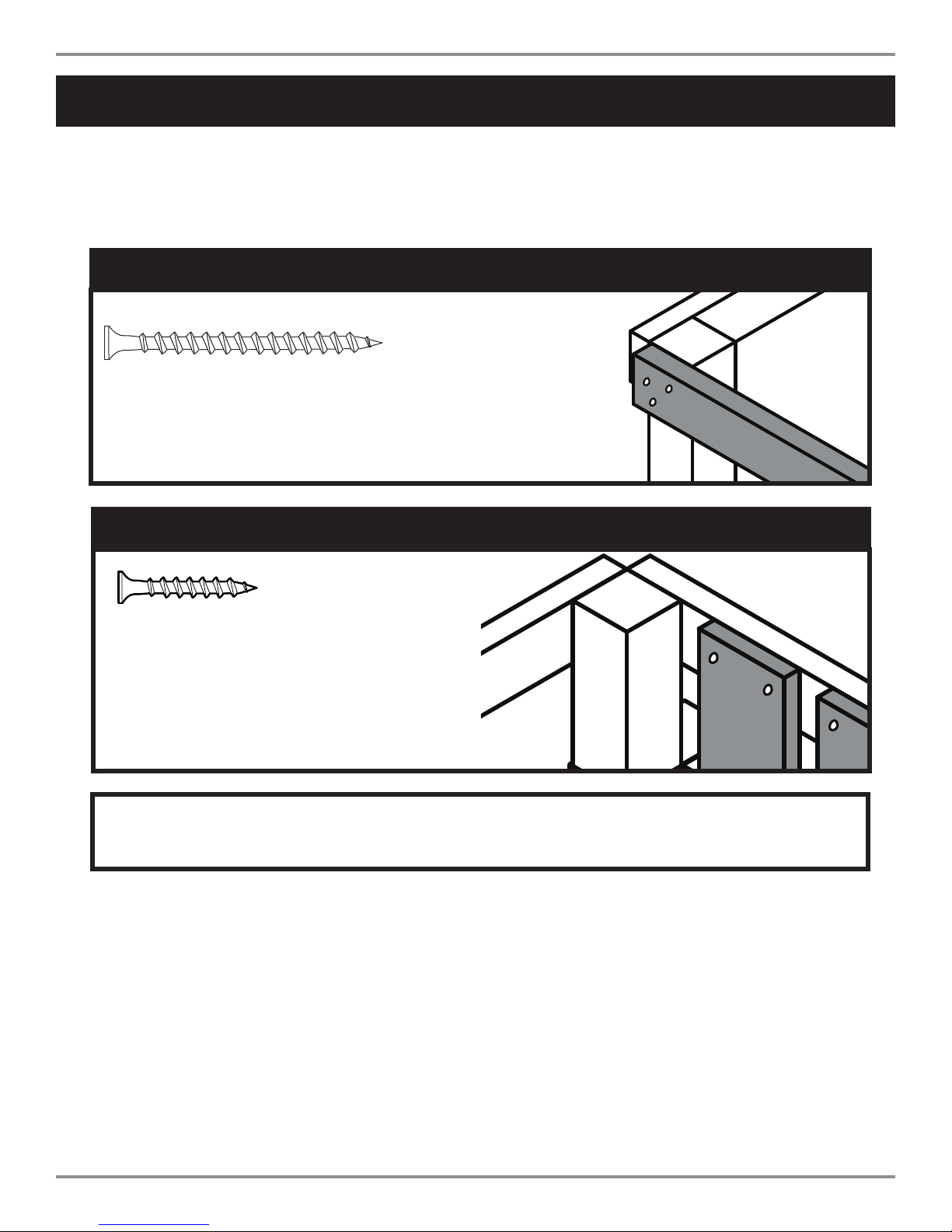
(3) 2-1/2'' screws
Apply 2-1/2'' screws to the 1'' x 4'' boards
when attach ng to 3'' x 3'' upr ghts or 2'' x 4''.
1'' x 4'' to 3'' x 3'' or 2'' x 4''
(2) 1-1/4'' screws
Use 1-1/4'' screws when mount ng 1'' x 4''
boards to 1''x4'' boards.
How to select the correct fastener
Use these 2 pictorial guides to help select the correct fastener(s) for the
lumber attachment you are making. Each diagram will highlight the correct
number of fasteners to use, and where to attach them.
1'' x 4'' to 1'' x 4''
"#(All hardware to be driven until flush with surface of
wood or no deeper that 1/16''.
9
Assembly Instructions
ASSEMBLY INSTRUCTIONS • INSTRUCCIONES PARA ARMAR • DIRECTIVES D’ASSEMBLAGE
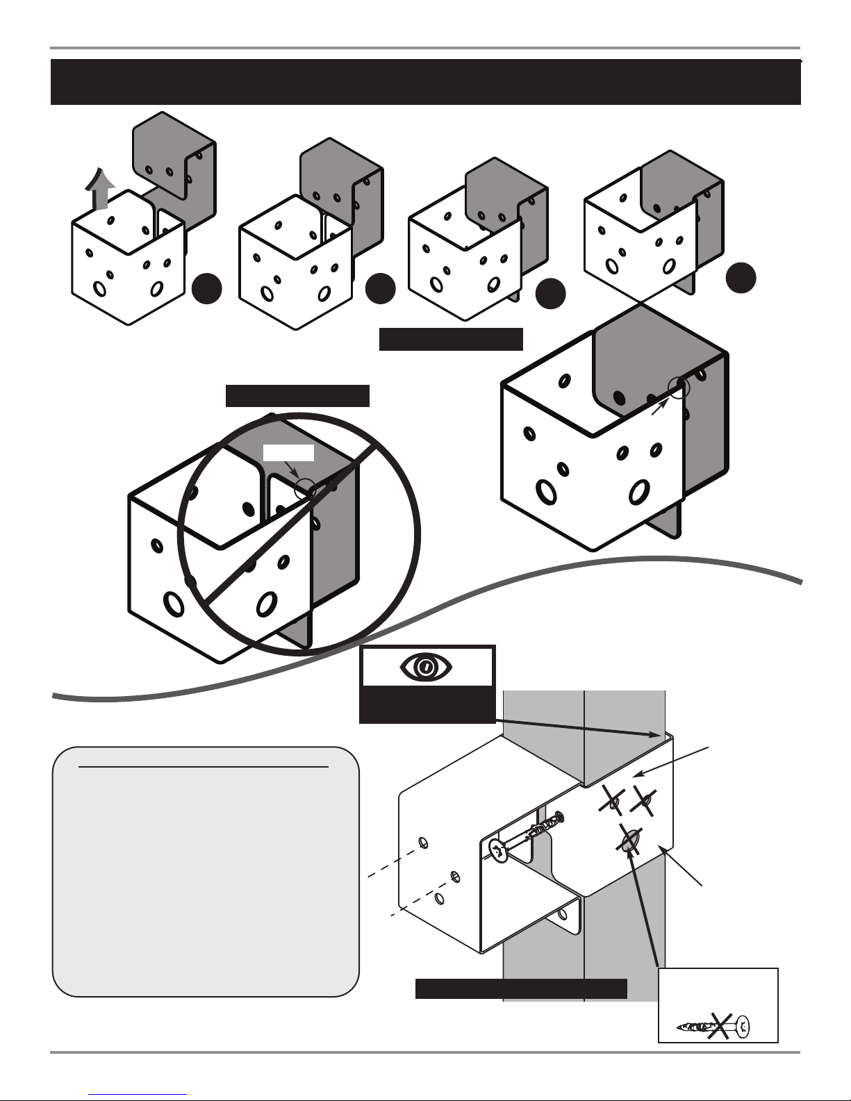
Understanding how the Bracket System Works
Shelf-Loc
GAP
(;< of bracket
;??;9 of bracket
(Hole locations close to bottom)
Example of a Shelf-Loc bracket connection.
Wrap-Loc
Shelf-Loc Bracket
1234
Wrap-Loc
#&&(
+&#"
=.072?>86<(;42?52=
/=.072?>"#(
6:?2=8;0721
=.072?>
086<<21
Example of a Shelf-Loc bracket connection.
TOP
Look for ''TOP'' stamp on
bracket for correct or entat on.
#"#()'
'&+'&
Use Lag Screws Only Where
Brackets Attach
Introduction to the Bracket system
1. ALWAYS Use 1-1/4'' or 2'' lag screws on
all brackets.
2. Brackets ''clip'' to each other. NEVER
position in a non-interlocking position.
NOTE: PLACE SCREWS IN BRACKETS ONLY
WHERE INSTRUCTED. DO NOT
FILL EVERY HOLE IN BRACKET.
THIS WILL LEAD TO HARDWARE
SHORTAGES.
10
Assembly Instructions
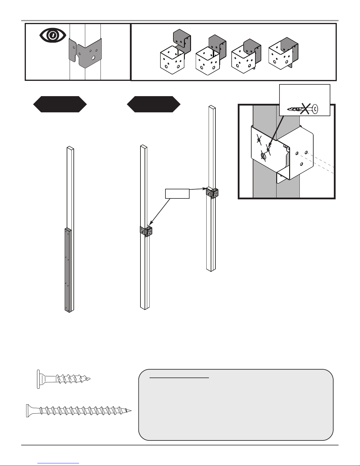
Frame 1 Assembly:
1. Using the boards illustrated in (Fi . 1), construct two laminated
uprights.
2. Attach brackets to your constructed uprights as shown in (Fi . 1a).
64
1-1/2'' x 3'' x 47-1/4'' [PF 3633]
2-1/2'' Wood Screw
(8)
2-1/2'' screws
per board
=.92
C
1-1/2'' x 3'' x 94'' [PF 3634]
FLUSH
64.
Look for ‘ ’TOP’’
stamp on brackets
while installing.
TOP
GAP on
this side
(2)
1-1/4'' Lag
Screws
per joint
#"#()'
'&+'&
Use Lag Screws Only Where
Brackets Attach
1-1/4''Lag Screw
(2)
1-1/4'' Lag Screws
per brac et
11
Assembly Instructions
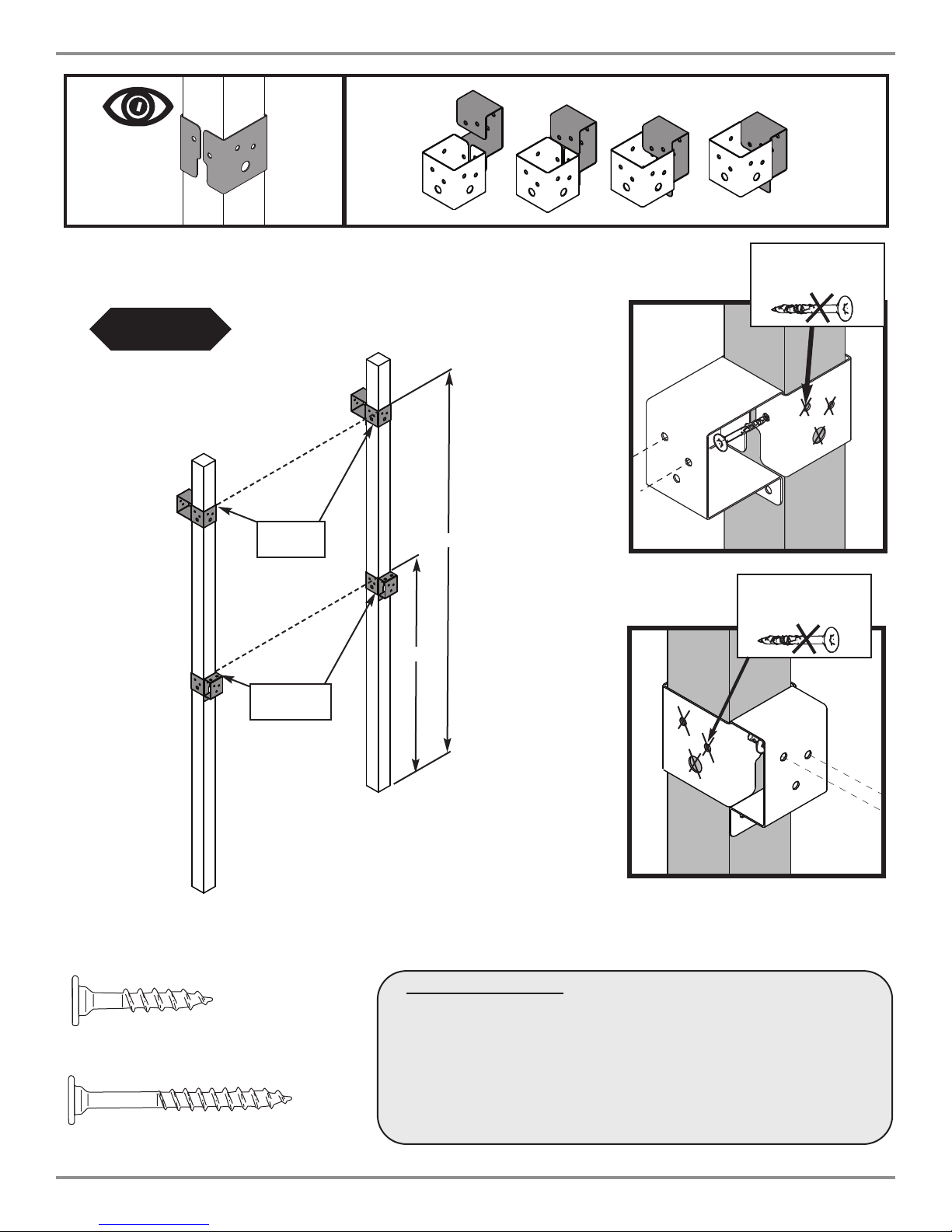
Frame 2 Assembly:
1. Using (2) PF 3636 uprights, attach brackets as shown in (Fi . 2).
3'' x 3'' x 94'' [PF 3636 ]
47-1/4''
=.92
3'' x 3'' x 94''[PF 3636 ]
84-1/2''
2''Lag Screw
Look for ‘ ’TOP’’
stamp on brackets
while installing.
TOP
GAP on
this side
(2)
1-1/4'' Lag
Screws
per joint
#"#()'
'&+'&
Use Lag Screws Only Where
Brackets Attach
#"#()'
'&+'&
Use Lag Screws Only Where
Brackets Attach
(2)
2'' Lag Screws
per joint
1-1/4''Lag Screw
(2)
1-1/4'' Lag Screws
per brac et
(2)
2'' Lag Screws
per brac et
64

12
Assembly Instructions
2-1/2'' Wood Screw
Frames 1 & 2 Assembly Cont.
1. Assemble Frame 1 as shown in (Fi . 3).
2. Assemble Frame 2 as shown in (Fi . 3a).
Note: Look to (Fi . 3b), (Fi . 3c), and (Fi . 3d) to properly
secure the brackets on both frames.
Tip: Flex brackets to make installation of
2'' x 4'' easier
Approx. 1/4''
•WARNING•
Avoid splitting your
lumber by offsetting
your screws at least
/4’’ from edge.
"#(Upper screws are (2) 1-1/4''
Lag Screws, Lower screws are (3) 2''
Lag Screws.
64/
641 (2)
1-1/4'' Lag
(3)
2'' Lag
Double check to make
sure structure is square
1''x 4'' x 47-1/2'' [PF 3623]
1'' x 4'' x 47-1/2'' [PF3623]
1'' x 4'' x 47-1/2'' [PF 3623]
1''x5''x47-1/2''[PF 3626 ]
=.92
=.92
64
64.
1-1/4'' Wood Screw
1-1/4'' Lag Screw
2''Lag Screw
2'' x 4'' x 47-1/2'' [PF3404]
2'' x4'' x 47-1/2'' [PF 3404]
(2)1-1/2'' x 4'' x 20'' [PF 3595]
78''
(3)
2-1/2'' screws
per joint
(3)
2-1/2'' screws
per joint
(3)
2-1/2'' screws
(per joint)
(3)
2-1/2'' screws
per joint
(3)
2-1/2'' screws
per joint
(2) 1-1/4'' lag screws
and
(3) 2'' lag screws
per brac et
(2) 1-1/4'' lag screws
and
(3) 2'' lag screws
per brac et
(6)
1-1/4'' screws
(per Brac et)
'($
&(
640

13
Assembly Instructions
Frame 1 & 2 Completion:
1. Attach (4) boards to Frame 2 as shown (Fi . 4).
2. Attach Frame 1 and Frame 2 as shown in (Fi . 4a).
2-1/2'' Wood Screw
2'' Wood Screw
64.
(3)
2-1/2'' screws
per joint
(3)
2-1/2'' screws
per joint
(3)
2-1/2'' screws
per joint
(3)
2'' screws
per joint
1''x5''x30'' [PF3625]
1''x5''x30''[PF3625]
1''x4''x28-1/2'' [PF 3618]
1''x 4''x28-1/2''[PF 3618]
=.92
=.92
78''
3/4'' Offset
3/4'' Offset
64
=.92
14
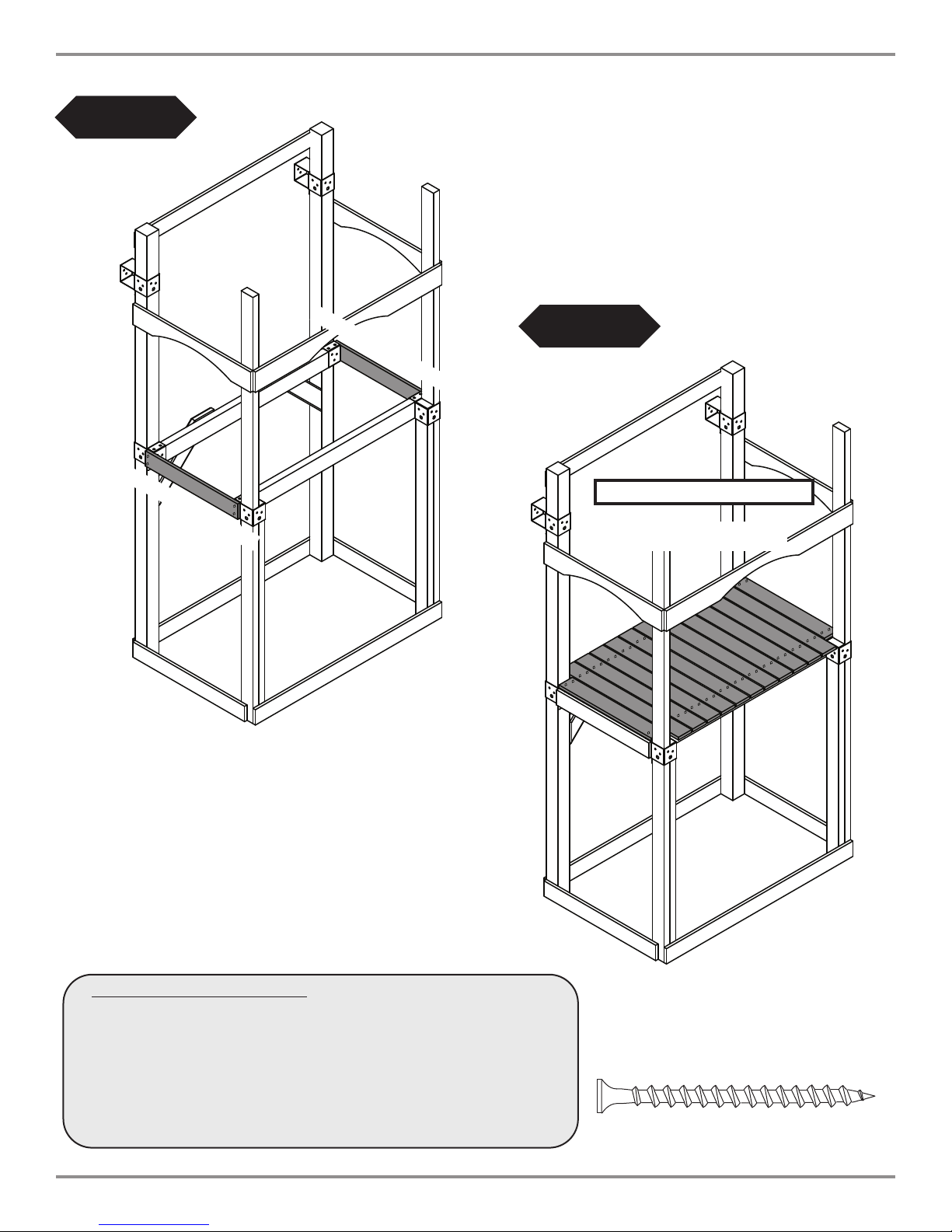
Assembly Instructions
Support Boards and Deck:
1. Attach (2) Frame Support Boards as shown in (Fi . 5).
2. Attach Deck Boards as shown in (Fi . 5a).
64
64.
2-1/2'' Wood Screw
(2)
2-1/2'' screws
per joint
1'' x 4'' x 23-1/2'' [PF 3617]
1'' x 4'' x 23-1/2'' [PF 3617]
(2)
2-1/2'' screws
per joint
(2) 1'' x 4'' x 23-1/2'' [PF 3617]
(11) 1'' x 4'' x 30'' [PF 3620]
(2)
2-1/2'' screws
per joint
"#( 5/16'' Gap Typical
15
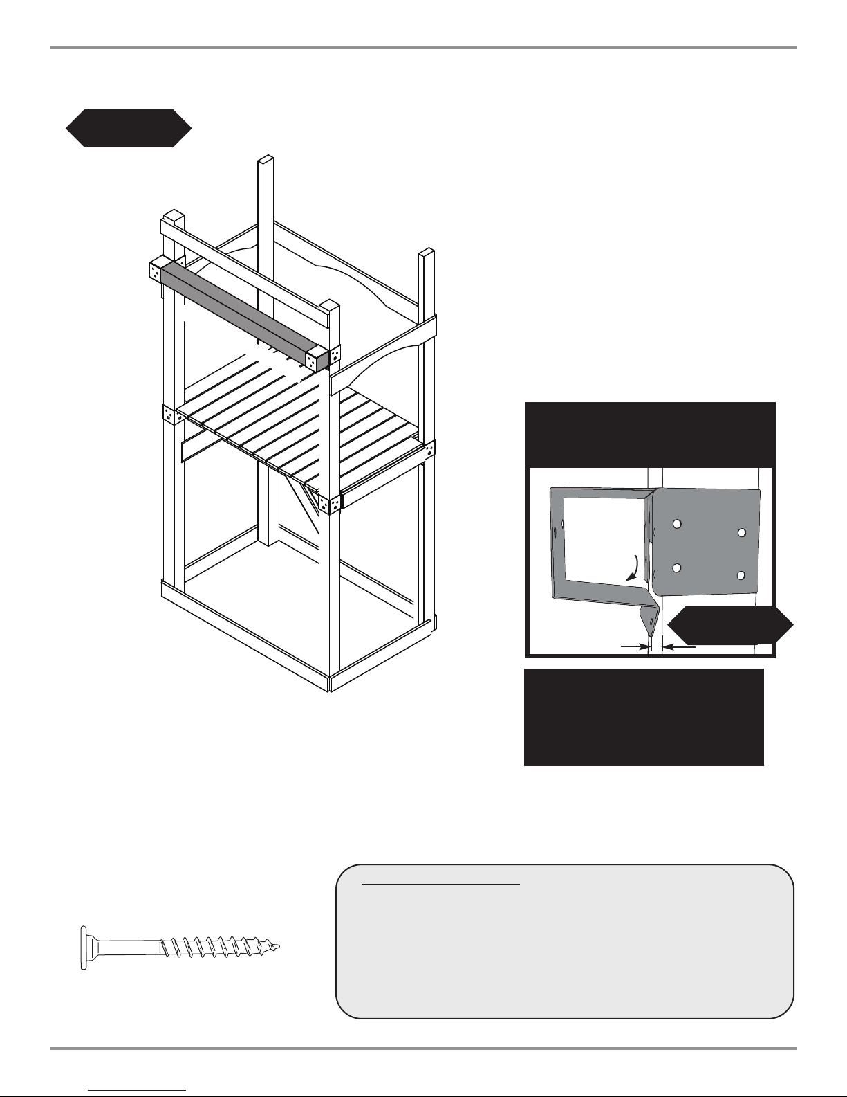
Assembly Instructions
64
Swin Beam Support:
1. Attach the Swing Beam Support as shown in (Fi . 6) and (Fi . 6a).
2''Lag Screw
(("(#"
):6?5.>/22:=;?.?21
?@=:;@:?2=
8;07B6>23;=?56>A62B
Tip: Flex brackets to make installation of
4'' x 4'' easier
64.
Approx. 1/4''
64.
4'' x 4'' x 47-1/2'' [PF 3405]
(5)
2'' lag screws
per joint
16
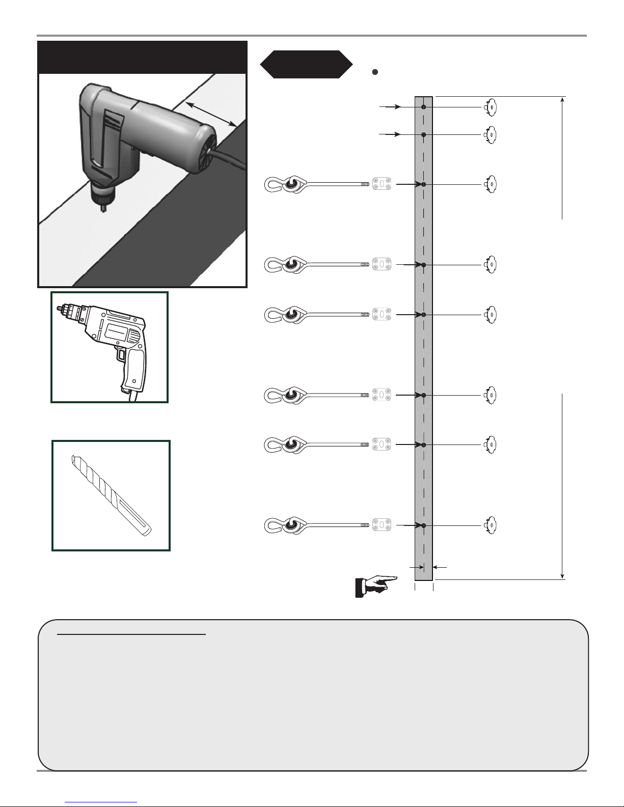
Assembly Instructions
64
1-1/2"
7-1/2"
17-3/8"
33-3/8"
43-1/4"
59-1/4"
69-1/8"
85-1/8"
Attach This End To Playset
1-1/2 "
6"
9-7/8"
16"
9-7/8"
16"
9-7/8"
16"
10-7/8"
96"
1-3/4"
3-1/2"
PLAYSET
3/8'' Hole Locations
A-Frame
RING TRAP
SWING
SWING
3-1/2''
Swin Beam Drill Locations:
1. Use a 3/8'' drill bit to drill a 3/8’’ hole through the beam at each location shown in (Fi . 7).
2. Tap T-Nuts into the swing beam at the locations shown in (Fi . 7).
3. Install Swing Hangers onto swing beam at locations shown, as shown in (Fi . 7) and (Fi . 8).
Note: Swing Hangers must be installed on the same side dimensions were originally marked.
+##)&CC
(&&
& (
!6:
Drill 3/8''
Hole
Swing Beam
TOP VIEW

17
Assembly Instructions
(4) 2'' screws
Swing Hanger
Use Screwdriver to aid in tightening
Bottom Beam Clamp
Hammer
3/8'' hole
64
T-nut
2'' Wood Screw
#&&(
Swin Han er Assembly
1. Tap T-nut into 3/8’’ hole as shown in Step 1.
2. Place a bottom beam clamp over the swing hanger as shown in Step 2.
3. Insert the swing hanger into the beam and thread it into the T-nut until it is flush or near flush with the top of the T-nut.
A screwdriver may be used to twist the hanger. Orient the Beam Clamp, making sure the slot is parallel with beam
length and the triangle of the Swing Hanger locks securely into the Beam Clamp slot, as shown
in Step 3.
4. Use (4) 2'' screws to secure beam clamp as shown in Step 4.
5. Check hanger to ensure it does not spin.
6. Repeat for all swing hangers.

18
Assembly Instructions
Align the edges of the 4" x 4" legs
with the edges of EZ Frame Bracket
64
(8) 2-1/2’’ Screws
2-1/2'' screw
A-Frame Assembly
1. layout 4'' x 4’’s and 2'' x 4'' as
shown in (Fi . 9).
2. Align EZ Frame Bracket with face of
4'' x 4''s.
3. Secure EZ Frame Bracket with (8)
2-1/2'' screws to 4'' x 4''s making
sure they are flush with each other.
4. Secure 2'' x 4'' to 4'' x 4''s as
shown in (Fi . 9a).
5. Flip over and add 2nd bracket.
Repeat steps 2 and 3.
94-1/2"
EZ F ame B acket
WOOD GUARD
4" x 4" x 96''
[PF 3636]
2" x 4" x 47-1/2"
[PF 3404]
WOOD GUARD
4" x 4" x 96''
[PF 3636]
2-1/2'' screws
2-1/2'' screws
64.
47-3/4"

19
Assembly Instructions
T-nut
2-1/2'' sc ews
Hex Bolt
Washe
3-1/2'' Hex Bolt
A-Frame Assembly cont.
1. Attach A-Frame to Swing Beam using (2) hex bolts and 4 screws as shown in (Fi . 10).
2. Tighten hex bolt to flush with top of T-nut. Repeat on second bracket.
64
2-1/2'' Wood Screw

20
Assembly Instructions
22''
Swing Beam
View from Deck
2'' Lag screw x 8 (each bracket)
Swing Beam
64.
A-Frame Assembly cont.
1.With the help of others, lift A-Frame and
Swing Beam Assembly and center onto unit as shown in
(Fi . 11).
2. Secure Swing Beam with Hardware shown in
(Fi . 11a).
64
Table of contents
Other Swing-N-Slide Outdoor Furnishing manuals


Popular Outdoor Furnishing manuals by other brands

Costco
Costco 3 Piece Sling Chaise Set Assembly / care & use instructions

StyleWell
StyleWell 1069Lg CH Use and care guide

Valkea
Valkea Franklin Playhouse Assembly, installation and maintenance manual

netta
netta LYQ205-45S Assembly & operation instructions

Costway
Costway OP70381 manual

BENITO
BENITO Urban Kube PA672S3 Anchoring instructions

Hanover
Hanover Foxhill FOXHILL3PC-GRY manual

Uberhaus
Uberhaus SWING BED L-GZ347PST-WTN Assembly instructions

leco
leco Hollywood Laureen 47 36400 214 manual

CAZEBOO
CAZEBOO BAHIA 300L300 manual

Sunjoy
Sunjoy L-BS692SAL Warnings & assembly instructions

Belson Outdoors
Belson Outdoors PARK MASTER PMB-WF manual


