Swiss Rotors FanSet SR190 User manual

1
Revision A.00
FanSet
OPERATION AND
MAINTENANCE
www.swissrotors.com

2
Revision A.00
Please read the following documentation carefully before installation of our product. In case of
TABLE OF CONTENT
1 INTRODUCTION.............................................................................................................................3
1.1 Preface...........................................................................................................................................3
1.2 Disclaimer.......................................................................................................................................3
2 PRODUCTDESCRIPTION...............................................................................................................4
2.1 Construction...................................................................................................................................4
2.2 Principleofoperation.....................................................................................................................6
2.3 Operationallimits...........................................................................................................................6
3 TRANSPORTATION........................................................................................................................9
3.1 Packing..........................................................................................................................................9
3.2 Quality control................................................................................................................................9
3.2.1 Examine the package:...................................................................................................................9
3.2.2 Examine the unit:...........................................................................................................................9
3.3 Storage...........................................................................................................................................9
4 INSTALLATION–MOTORCONNECTION.....................................................................................10
4.1 Generalsafety................................................................................................................................10
4.2 Productdescription........................................................................................................................10
4.4 Connection & Diagrams...............................................................................................................13
4.5 Communication...........................................................................................................................16
4.5.1 Analog input.................................................................................................................................16
4.5.2 Modbus RTU................................................................................................................................16
5 MAINTENANCE............................................................................................................................21
5.1 Maintenance................................................................................................................................21

2 3
Revision A.00
1. INTRODUCTION
1.1 Preface
To ensure trouble-free usage of our products we would like to provide the following technical and
commissioning documentation. This manual is to help at every stage of use. Mandatory maintenance
service tasks that are responsibility of the user, from appropriate transportation methods to periodic
inspections. All the crucial information and warnings will be preceded by various caution symbols
as shown below:
Electrical Voltage
Important Information
Useful Hint
start-up. Improper use of the product may void the warranty.
Keep it as a reference for future maintenance and service procedures.
1.2 Disclaimer
The following instruction, unless otherwise stated, applies to all Swiss Rotors FanSet units. In exceptional
protected by international trademark and copyright laws. Swiss Rotors constantly develops its products and
this document is subject to change without notice.

4
Revision A.00
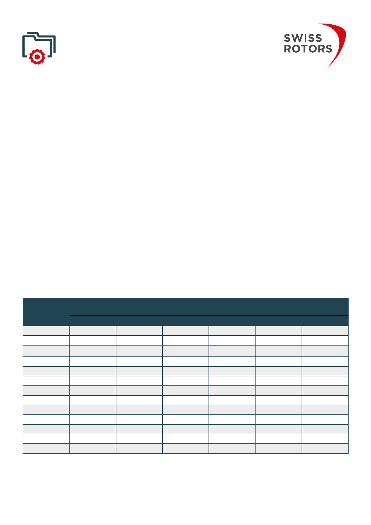
Table 1. Swiss Rotors FanSet models and dimensions
2 PRODUCT DESCRIPTION
2.1 Construction
Swiss Rotors FanSet is designed specially to replace an old fan systems solutions used in
air handling units. FanSet consist of two steel plate’s integrated by spacing sleeves. Properly
of dedicated diameter is mounted on the opposite side. Each of fans Series 225, 250 and
315 have two pressure tabs. The exception is Fan 190 Series which have one pressure tab.
All parts are made of high quality materials:
- Support bracket and plate: Sheet steel, galvanized
- Impeller: plastic
- Electronics housing: Die-cast aluminum.
All parts create perfectly optimized air supply/exhaust device. Depending on customer needs,
mounted into balancing machine. At the next step, balancing of the fan needs to be performed by
screen. FanSet is balanced and ready to operate after successful placing of the balancing weight.
FanSet models listed below:
FanSet Model Rated voltage Rated Output
Power
Rated Current Rated Speed L A
[W] [W] [A] [rpm] [mm] [mm]
SR190 230 128 1,2A 4490 120 220
SR225-03 230 349 2,3A 3600 250 300
SR225-03_UL 110/240 349 2,6A 3600 250 300
SR250-03 230 349 2,3A 3000 260 330
SR250-03_UL 110/240 349 2,6A 3000 260 330
SR315-03 230 1,5A 2060 310 400
SR315-03_UL 110/240 1,5A 2060 310 400
230 5,4A 4500 300
110/240 3,2A/230VAC 4500 300
230 5,1A 3800 290 330
110/240 3800 290 330
230 3,8A 2600 340 400
110/240 3,3A/230VAC 2600 340 400

4 5
Revision A.00
Figure 1.
Figure 2. Balancing weight
Figure 3. Swiss Rotors FanSet overall dimensions

6
Revision A.00
Detailed dimensions are included within the company technical documentation:
- SR225-03 ASM
- SR250-03 ASM
- SR315-03 ASM
- SR190 ASM
2.2 Principle of operation
FanSet is a device used to supply and exhaust air. The engine, mounted in the housing, drives the
impeller located inside. The fan, after accelerating to the dedicated rotational speed, is able to force
in frame redirect exhaust of air at 90 degrees so that the centrifugal effect increases the pressure
and power of the fan. Ventilating cone of dedicated diameter is mounted on the opposite side. All
parts are made of high quality materials:
Fig. 4 presents the principle operation of the FanSet inside the Air Handling Unit. It is crucial to note
Figure 4. FanSet’s inside AHU Figure 5.
2.3 Operational limits
Impeller units inside the FanSet are prepared to work within temperature conditions oscillating

6 7
Revision A.00
2.4 Serialnumberidentication
Labels are attached directly on the casing and provide essential information about the product.
The label consists of the following information:
• Type
• Power
• Size
• Serial number
• Quality check date
• QR Code
By serial number and model name it is possible to identify
your product and answer your question effectively and
immediately.
While contacting our company make sure to have your serial number in sight.
Figure 6. FanSet’s label sticker
Nameplateeld Explanation
Fan Type The manufacturer’s product name to indicate the particular type which has been acquired.
Power Nominal power of engine which is used to drive fan.
Size Nominal size of fan impeller.
Serial number
warranty purposes.
Quality check date Date of checking and approval of correct operation of the device.
QR Code Unique code to call a service.
Table 2.
2.5 Air volume measuring
FanSet units are equipped with the inlet cone. Air volume measuring device with circular lead is
direction . With the assistance of the measuring device it is possible to control the air volume
depending on the difference in pressure between the static pressure at the inlet cone and the static
pressure on the inlet area. This sensor cannot measure the dynamic pressure in the inlet area. While
Fan Set is tested it is possible to regulate air volume.
The air volume is calculated according to the following formula.

8
Revision A.00
Figure 7. Air Volume measurement method
is determined by comparative measurement on a standard test rig. For Swiss Rotors FanSet’s the
calculated K factor’s have the following values:
- FanSet SR190 : k=36
- FanSet SR225 : k=49
- FanSet SR250 : k=56
- FanSet SR315 : k=105

8 9
Revision A.00
Figure 8. Packing model
3 TRANSPORTATION
3.1 Packing
To avoid dents or scratches on the surface please make sure to properly secure the package
for the transportation.
3.2 Quality control
3.2.1 Examine the package:
1. Before accepting the delivered parcel, carefully
check the condition of the package in the presence of a
shipping company representative. Look for any signs of
transportation damage. Our FanSet’s are precisely and
tightly secured for the shipment. Any signs of tearing,
punctures, damage exposing the goods being delivered
or traces of opening are not acceptable.
2. Pay attention to the way in which the goods were
delivered. – Fig.8.
3. SwissRotorspreparesshipmentsusingprofessional
labels and transport descriptions. If you see that the
shipping company did not follow the instructions given
on the labels - refuse to accept the parcel.
5. In case of noticing any damage please contact our support immediately – phone numbers
3.2.2 Examine the unit:
1. Remove packing materials from the product.
2. Dispose all packing materials in accordance with local regulations.
3. To determine whether any parts have been damaged or are missing, examine the product
carefully.
4. If there is any issue, please contact our support.
3.3 Storage
If the FanSet is not installed immediately, leave the product in its original packaging and
follow the rules of proper storage.
Prolonged exposure of the product to the improper conditions may damage and shorten the
lifetime of the device.
• Avoid exposure to moisture, excessive sunlight and other weather conditions.
• Secure the fans against mechanical damages.

10
Revision A.00
4 INSTALLATION – MOTOR CONNECTION
4.1 General safety
The following section contains valuable notes and list of mandatory procedures which are
responsibility of the user. Neglecting advices collected in this chapter may result in product
damage or void of warranty. Take time to study carefully whole chapter and make sure everything is
understandable. If you have any questions, please contact support.
FanSet needs to be installed in a way enabling seamless execution of future maintenance
tasks.
CAUTION! Electric Voltage: All motors described in the following manual can be operated,
in any of this operations may result in risk of fatal injury, electric shock, incorrect mounting or product
damage. Installation should be carried out with usage of power lines, without short circuits and with
proper grounding. Follow the connection diagrams dedicated to given motors.
WARNING: Do not open or disassemble the motor while power supply is connected to the device. It
may result in fatal injury caused by electric shock. If it is necessary to open the motor, wait at least
5 minutes after disconnecting from the power supply.
NOTE: It is the user and the installer responsibility to provide the system with the proper grounding
and protection in accordance with national and local standards. Swiss Rotors is not responsible for
any damages or injuries caused by incorrect installation, bad circuits or other failures.
Before installation and operating the motor please read entire instruction carefully! Follow the
connection diagrams to perform successful installation.
4.2 Product description
electrical requirements of our customers. To get the right parameters and to ensure proper operation
shows the motors used in the fans and operating parameters – mechanical and electrical.
Note:

10 11
Revision A.00
Table 3.
FAN TYPE MOTOR TYPE RATED
VOLTAGE FREQUENCY RATED
CURRENT
RATED
TORQUE
RATED
OUTPUT
POWER
RATED
SPEED
SPEED
CONTROL
OPERATING
TEMP. [C]IP
SR190 EC169W-
-B190/44P1-05
230V AC 50/60Hz 1,2A - 128W 4490
rpm
0~10VDC,
Modbus RTU
-25to 6044
SR225-03 EC092/25E3G01-03 230V AC 50/60Hz 2,3A 0,93 Nm 349W 3600
rpm
0~10VDC,
Modbus RTU
-25to 6054
SR225-03
UL
EC092/25EF3G-
03-02,UL
110/240V
AC
50/60Hz 2,6A 0,93 Nm 349W 3600
rpm
0~10VDC,
Modbus RTU
-25to 6054
SR250-03 EC092/25E3G01-04 230V AC 50/60Hz 2,3A 1,11 Nm 349W 3000
rpm
0~10VDC,
Modbus RTU
-25to 6054
SR250-03
UL
EC092/25EF3G-
03-03,UL
110/240V
AC
50/60Hz 2,6A 1,11 Nm 349W 3000
rpm
0~10VDC,
Modbus RTU
-25to 6054
SR315-03 EC092/35E3G01-03 230V AC 50/60Hz 1,5A 2060
rpm
0~10VDC,
Modbus RTU
-25to 6054
SR315-03
UL
EC092/35EF3G-
01-02,UL
110/240V
AC
50/60Hz 1,5A 2060
rpm
0~10VDC,
Modbus RTU
-25to 6054
EC102/35E3G03-03 230V AC 50/60Hz 5,4A 1,56 Nm 4500
rpm
0~10VDC,
Modbus RTU
-25to 6054
UL
EC102/35E3G-
01-02,UL
110/240V
AC
50/60Hz 3,2A
/230VAC
1,56 Nm 4500
rpm
0~10VDC,
Modbus RTU
-25to 6054
EC102/35E3G03-04 230V AC 50/60Hz 5,1A 3800
rpm
0~10VDC,
Modbus RTU
-25to 6054
UL
EC102/35E3G-
01-03,UL
110/240V
AC
50/60Hz
/230VAC
3800
rpm
0~10VDC,
Modbus RTU
-25to 6054
EC102/50E3G03-02 230V AC 50/60Hz 3,8A 2600
rpm
0~10VDC,
Modbus RTU
-25to 6054
UL
EC102/50E3G-
01-02,UL
110/240V
AC
50/60Hz 3,3A
/230VAC
2600
rpm
0~10VDC,
Modbus RTU
-25to 6054
Changing the settings is associated with poor fan performance and risk of motor damage as well as electric
loss of warranty.
4.3 Technicalspecications
Drawings below presents the overall dimensions of the motors used in FanSet units. Figure 9 shows
Figure 9.

12
Revision A.00
Figure 10.
numbers. The index number is a unique code identifying the right motor for the product.
FAN TYPE MOTOR TYPE INDEX L [mm] L1 [mm]
SR225-03 EC092/25E3G01-03 1-2-2214-0182 105
SR225-03UL EC092/25EF3G-
03-02,UL 1-2-2214-0188 105
SR250-03 EC092/25E3G01-04 1-2-2214-0184 105
SR250-03UL EC092/25EF3G-
03-03,UL 1-2-2214-0190 105
SR315-03 EC092/35E3G01-03 1-2-2214-0186 116 88
SR315-03UL EC092/35EF3G-
01-02,UL 1-2-2214-0192 116 88
EC102/35E3G03-03 1-2-2214-0183 131,5 88
EC102/35E3G-
01-02,UL 1-2-2214-0189 131,5 88
EC102/35E3G03-04 1-2-2214-0185 131,5 88
EC102/35E3G-
01-03,UL 1-2-2214-0191 131,5 88
EC102/50E3G03-02 146,5 103
Table 4.

12 13
Revision A.00
4.4 Connection & Diagrams
To perform the correct setup, please refer to the following diagrams representing possible
only. Failure in performing in any of this operations may result in risk of fatal injury, electric
shock, incorrect mounting or product damage.
WARNING: Do not open or disassemble the motor while power supply is connected to the device. It
may result in fatal injury caused by electric shock. If it is necessary to open the motor, wait at least
5 minutes after disconnecting from the power supply.
Notes on proper installation:
• Use fuses at power line
• Check the wires condition before operating. Make sure that there are no short circuits.
• Use shield cable.
cables that are adapted to work with the desired current.
Connection instructions:
1. Remove the Top cover of the terminal strips.
2. Fasten the control and main power wires by screwing them to the connector.
3. Check all connections again and carefully replace the Top cover.
4. Connect the Power supply voltage.
Motor EC169W-B190/44P1-05

14
Revision A.00
Figure 11. EC169W-B190/44P1-05 CONNECTION DIAGRAM
Figure 12. Wires and factory connectors EC169W-B190/44P1-05

14 15
Revision A.00
Figure 13. EC092 series and EC102 series CONNECTION DIAGRAM
Motor EC092 series and EC102 series

16
Revision A.00
Incorrect polarity at input AN1 can cause serious damage of the controller.
4.5.2 Modbus RTU
Electronics are equipped with Modbus RTU 485 communication. To connect controllers into chain
use only shielded cables. Shielded wires for grounding connection between controllers is necessary.
4.5 Communication
The motors can be controlled via an analog connection and using the Modbus protocol. The
EC169W-B190 / 44P1-05 engine can only be controlled using the Modbus protocol. The 092 and 102
series motors can be controlled in both ways. The parameters and control methods are presented
below.
5.5.1 Analog input
AN1: Analogue input 1 – Electronics can be controlled by external analogue input voltage 10-0 VDC.
AN1Min parameter can be set to the desired minimum setpoint. AN1Max parameter can be set to
the desired maximum setpoint. AN1Min and AN1Max can be set from 0V to 10V.
By AN1Stop, stop threshold voltage can be set. If AN1Stop is 0 threshold voltage is disabled and
motor will run with minimal settable RPM. By setting AN1Stop higher than 0 motor will not run up to
settable value.
For example if AN1min is set to 1V, AN1max is set to 9V and AN1stop is set to 0V controller works
from 200 rpm to 1500 rpm and motor will run with minimal rpm. AN1 operates from 1V to 9V
Figure 14. RPM/voltage charts with analogue connection.

16 17
Revision A.00
Drives uses the two-wire system where the communication between master and slave is half duplex,
i.e. it cannot transmit and receive at the same time. Each signal uses one twisted pair line — two
wires twisted around themselves. The signal on one wire is ideally the exact opposite of the signal
on the second wire. Since RS-485 is a multipoint communication system, all devices are connected
to the single twisted-pair cable. The Modbus RTU uses master/slave architecture, where each slave
device has its unique address and responds only to packets addressed to this device. The packets
travels over the single line in both directions. Multiple EC drives can be connected to a control
connected to the network is 32. Use parallel connections method to connect multiple frequency
converters.
is needed.
4.5.3 Modbus parameters
Coils
Address Function Range Description Level
0 Motor ON/OFF 0-1 Indication, 1=ON,
0=OFF
0
1 Reset Controller 0-1 1=Reset controller 0
Figure 14. Parallel and “Daisy chain” connections via modbus

18
Revision A.00
Discrete status bits
Address Function Range Description Level
0 Under Voltage 0-1 1=Voltage too low to run 0
1 Over Voltage 0-1 1=Voltage too high to run 0
2 IGBT Overcurrent 0-1 1=Overcurrent protection tripped 0
3 Hot 0-1 1=Temperature protection active, power
reduced
0
4 Phase Loss 0-1 1=Phase or motor sync loss 0
5 RESERVED 0
6 Parameters CRC 0-1 0
Circuit Fault 0-1 1=There was an error detected during circuit
internal check
0
8 Motor Fault 0-1 1=Motor does not behave as expected 0
9 Too Hot 0-1 1=Converter too hot to operate 0
10 I2R IGBT Fault 0-1 1=Software IGBT protection triggered 0
13.lis RESERVED 0
14 Restart Fault 0-1 1=Fault condition repeated several times in a
short time. Converter power should be power
cycled or reset.
0
15 RESERVED 0
RESERVED 0
18 Waiting To Stop 0-1 1=Motor should be stopped, but is still spin-
ning
0
19 – 23 RESERVED 0
24 RpmReg 0-1 Speed regulator active 0
25 PowerReg 0-1 Power limit regulator active 0
26 RESERVED 0
OvermodReg 0-1 Over modulation reached. Converter can no
longer supply the voltage required by motor.
0
28 RegenReg 0-1 Motor is in regeneration. Speed increased to
prevent DC link over voltage
0
29 IphaseReg 0-1 RMS motor phase current limit reached 0
30 SyncReg 0-1 Motor is still in Synchronous mode 0

18 19
Revision A.00
Holding Registers
Address Function Range Description LEVEL Resolution
0 Set point 0..10000 Performance set point for speed depends on operation
mode.
0, 1
1 Direction 0..65535 Motor direction:
0: clockwise rotation.
1 1
2 Maximum Speed MinRPM.. Ma-
xRPM[level+1]
Max rpm allowed in normal operation. External control
will use this as set point maximum.
0, 1 1
3 RESERVED
4 MinRPM[level+1]…
MaxRPM
RPM
Minimal allowed speed 0, 1 1
5 Password 0: level 0
24681: password for level 1
24681 can be changed
When level is changed, stored values for the level will
be loaded
0
6 Operation Mode
2: MODBUS Speed
0
Modbus Address Set Modbus address:
Write 10000 to Password to save. Restore by writing to
1
8 MODBUS connection
detection
0/1 Detection MODBUS connection loos
0
9 MODBUS connection
detection timeout
0..65536 s timeout to stop motor after loose connection 1
10 RESERVED
11 AN1Max 0..1000 Voltage for maximum setpoint.
Transfer function is inverted if AN1Max < AN1Min.
1 0.01V
12 AN1Min 0..1000 Voltage for minimum setpoint 1 0.01V
13 AN1Stop 0..1000 0: disable stop
1 0.01V
18 Modbus speed 1-3 Modbus speed can be changed: 1 - baud rate 9600
Notice: after baud rate change Modbus communica-
tion will not work, also change baud rate on converter
to get proper working.
19 RESERVED
20 RESERVED
21 Password change new password for level 1

20
Revision A.00
Input Registers
Address Function Range Description LEVEL Resolution
0 HW Version Hardware version 0 1
1 FW Version Firmware version 0 1
2..3 RESERVED 0
4 Speed RPM 0 1
5 Controller
temperature
-50..150 °C 0 0.01
6 UDC DC Bus voltage in V 0 0.1
Stator IRMS RMS Stator current in A 0 0.001
8 Power W 0 0.1
9 Analogue1 -300..2000 Analogue input 1 voltage 0 0.01V
19 Error Code
6 = under or overvoltage
5 = motor misconnected/faulty
4 = internal frequency converter fault
3 = temperature protection active
2 = active overcurrent protection
1 = slow blink = standby
0
20 - 21 RESERVED 0
23 Op Minutes Minutes of operation 0
24 Op Days 0
This manual suits for next models
12
Table of contents
Other Swiss Rotors Fan manuals
Popular Fan manuals by other brands

Ruck Ventilatoren
Ruck Ventilatoren DVA ECP31 Series Assembly instruction

Panasonic
Panasonic FV-08/11/15VQL4 Service manual

QuietCool
QuietCool AFG installation guide

Progress Lighting
Progress Lighting AirPro P250062 installation manual

NuAire
NuAire DRI-ECO3S-HEAT-HC installation manual

Alnor
Alnor HRU-PremAIR-350 user manual