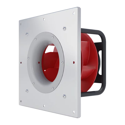
Swiss Rotors SR-FS-P-190-0.1 User manual

190-560 mm SR-FS-P/A Fan Sets / Operating Manual Ver. 2023-08-01 EN
Page 1 of 17
190-560 MM SR-FS-P/A FAN SETS
OPERATING MANUAL

190-560 mm SR-FS-P/A Fan Sets / Operating Manual Ver. 2023-08-01 EN
Page 2 of 17
LIST OF CONTENTS
1Introduction............................................................................................................................................................................... 3
2Product Description ................................................................................................................................................................. 3
3Installation –motor connections ............................................................................................................................................ 8
3.4.1 Analog input .......................................................................................................................................................... 11
3.4.2 Modbus RTU ......................................................................................................................................................... 12
3.4.3 Modbus Parameters............................................................................................................................................. 13
3.5.1 Thermal protection ............................................................................................................................................... 15
3.5.2 Under and over voltage ....................................................................................................................................... 15
3.5.3 Blocked rotor protection...................................................................................................................................... 15
3.5.4 Motor phase fail/lose ............................................................................................................................................ 15
3.5.5 Phase overcurrent protection ............................................................................................................................. 15
3.5.6 Rotor failed acceleration...................................................................................................................................... 15
4Maintenance ........................................................................................................................................................................... 15
5Transportation ........................................................................................................................................................................ 16
5.2.1 Examine the package........................................................................................................................................... 17
5.2.2 Examint the Unit.................................................................................................................................................... 17
5.2.3 Storage .................................................................................................................................................................. 17
6Support.................................................................................................................................................................................... 17

190-560 mm SR-FS-P/A Fan Sets / Operating Manual Ver. 2023-08-01 EN
Page 3 of 17
1INTRODUCTION
LEGAL DISCLAIMER
This Operations Manual (OM) applies to products of Swiss Rotors. This document is a property of Swiss Rotors, licensors
or affiliates, protected by international trademark and copyright laws.
Due to continuous product improvement, Swiss Rotors reserves the right to make changes to its content without prior
notice. The introduction of changes will take place through the release of a new version of the document. The version
information is visible in the footer of each page of this manual on the right (Ver. expressed by date of release in YYYY-
MM-DD format, followed by language marking.
PREFACE
This OM contains a number of important information regarding the construction, storage, transport, installation and
operation of Swiss Rotors products. The most critical information from the point of view of the above-mentioned aspects
are written in the form of highlighted precautions (red symbol followed by text description).
GENERAL PRECAUTIONS
Read this manual in its entirety before installing, commissioning and operating Swiss Rotors products.
Improper use of the product contrary to the recommendations of this OM may cause damage not covered
by the warranty. If in doubt, contact Swiss Rotors Technical Support.
For warranty claims, please prepare a full set of Swiss Rotors product identification information: Product type,
size and serial number. This information is available on the product nameplates. Reports of defects covered
by the warranty should be reported immediately after its occurrence. Damage resulting from transport should
be directed to the carrier to whom the transport was entrusted. The Swiss Rotors product warranty does not
cover damage resulting from improper installation, use or maintenance.
Failure to follow the guidelines of this OM can result in significant property damage and, in extreme cases,
serious personal injury, including death.
Under no circumstanced DO NOT connect any Swiss Rotors products to mains, before getting familiar with
entire content of this OM.
2PRODUCT DESCRIPTION
DESIGN
Swiss Rotors new high efficiency FanSet range is designed especially to replace an old fan systems solutions that makes
air handling units low efficient. FanSet consists of front steel plate with inlet cone that is integrated with specific motor
tubular support. Properly selected EC electric motor mounted on the tubular support is driving a radial impeller located
directly on the motor flange. Swiss Rotors impeller has 7 backward-curved blades in frame. Ventilating cone that are
mounted on the front plate of FanSet has it’s strictly designed shape for each size of the impeller. Series 225-560 have
two pressure taps integrated with cone that are perpendicular to airflow axis. The exception is Fan 190 Series which
have one pressure tap. All parts are made of high quality materials:
•Front plates, inlet cones made of galvanized steel,
•Supports made of steel and painted,
•Impeller material:
oSR-FS-P -plastic material reinforced with glass fiber
oSR-FS-A –aluminum alloy
•Electronics housing: Die-cast aluminum.

190-560 mm SR-FS-P/A Fan Sets / Operating Manual Ver. 2023-08-01 EN
Page 4 of 17
All parts create perfectly optimized air supply/exhaust device. Depending on customer needs, FanSet’s comes in few configurations (
Figure 1 - Appearance of the SR-FS-P-190-0.1 Fan Set
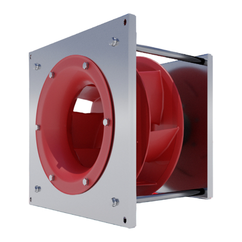
Figure 2 - Appearance of the SR-FS-P/A-225-0.3
→
SR-FS-P/A-400-2.5 Fan Sets
Figure 3 - Appearance of the SR-FS-A-315-560 Fan Sets
Table 1 - Dimmensions of SR-FS-P/A-225-0.3
→
SR-FS-P/A-400-2.5
FanSet Model
A
B
C
D
E
F
G
Ø
SR-FS-P-190-0.1
120 mm
97 mm
190 mm
2 mm
220 mm
195 mm
180 mm
9 mm
SR-FS-P-225-0.3
224 mm
199 mm
254 mm
15 mm
315 mm
288 mm
228 mm
9 mm
SR-FS-A-225-0.3
222 mm
199 mm
254 mm
15 mm
315 mm
288 mm
228 mm
9 mm
SR-FS-P-250-0.3
236 mm
211 mm
285 mm
15 mm
375 mm
336 mm
258 mm
9 mm
SR-FS-A-250-0.3
232 mm
211 mm
285 mm
15 mm
375 mm
336 mm
258 mm
9 mm
SR-FS-P-315-0.3
271 mm
246 mm
358 mm
15 mm
450 mm
411 mm
328 mm
9 mm

190-560 mm SR-FS-P/A Fan Sets / Operating Manual Ver. 2023-08-01 EN
Page 5 of 17
SR-FS-A-315-0.3
268 mm
246 mm
358 mm
15 mm
450 mm
411 mm
328 mm
9 mm
SR-FS-P-225-0.7
250 mm
210 mm
254 mm
15 mm
315 mm
288 mm
228 mm
9 mm
SR-FS-A-225-0.7
248 mm
210 mm
254 mm
15 mm
315 mm
288 mm
228 mm
9 mm
SR-FS-P-250-0.7
262 mm
221 mm
285 mm
15 mm
375 mm
336 mm
258 mm
9 mm
SR-FS-A-250-0.7
259 mm
221 mm
285 mm
15 mm
375 mm
336 mm
258 mm
9 mm
SR-FS-P-315-0.7
302 mm
261 mm
358 mm
15 mm
450 mm
411 mm
328 mm
9 mm
SR-FS-A-315-0.7
298 mm
261 mm
358 mm
15 mm
450 mm
411 mm
328 mm
9 mm
SR-FS-P-315-1.5
328 mm
282 mm
358 mm
15 mm
450 mm
411 mm
328 mm
9 mm
SR-FS-A-315-1.5
324 mm
282 mm
358 mm
15 mm
450 mm
411 mm
328 mm
9 mm
SR-FS-P-315-2.5
351 mm
304 mm
358 mm
15 mm
450 mm
411 mm
328 mm
9 mm
SR-FS-A-315-2.5
349 mm
302 mm
358 mm
15 mm
450 mm
411 mm
328 mm
9 mm
SR-FS-A-355-1.6
360 mm
313 mm
406 mm
20 mm
500 mm
461 mm
373 mm
9 mm
SR-FS-A-355-2.5
379 mm
332 mm
406 mm
20 mm
500 mm
461 mm
373 mm
9 mm
SR-FS-A-355-3.7
394 mm
328 mm
406 mm
20 mm
500 mm
461 mm
373 mm
9 mm
SR-FS-A-400-1.6
373 mm
326 mm
457 mmm
20 mm
550 mm
512 mm
418 mm
9 mm
SR-FS-A-400-2.5
393 mm
346 mm
457 mmm
20 mm
550 mm
512 mm
418 mm
9 mm
Table 2 - Dimmensions of SR-FS-A-400-3.7
→
SR-FS-A-560-5.4
FanSet Model
A
B
C
D
E
F
G
H
Ø
SR-FS-A-400-3.7
424 mm
359 mm
457 mm
20 mm
550 mm
512 mm
418 mm
-
9 mm
SR-FS-A-400-5.4
454 mm
389 mm
457 mm
20 mm
550 mm
512 mm
418 mm
-
9 mm
SR-FS-A-450-1.6
398 mm
353 mm
515 mm
20 mm
600 mm
562 mm
468 mm
250 mm
9 mm
SR-FS-A-450-2.5
438 mm
374 mm
515 mm
20 mm
600 mm
562 mm
468 mm
250 mm
9 mm
SR-FS-A-450-3.7
468 mm
404 mm
515 mm
20 mm
600 mm
562 mm
468 mm
250 mm
9 mm
SR-FS-A-450-5.4
468 mm
404 mm
515 mm
20 mm
600 mm
562 mm
468 mm
250 mm
9 mm
SR-FS-A-500-3.7
484 mm
420 mm
579 mm
25 mm
670 mm
622 mm
518 mm
250 mm
11 mm
SR-FS-A-500-5.4
519 mm
455 mm
579 mm
25 mm
670 mm
622 mm
518 mm
250 mm
11 mm
SR-FS-A-560-3.7
500 mm
435 mm
644 mm
25 mm
730 mm
662 mm
580 mm
250 mm
11 mm
SR-FS-A-560-5.4
535 mm
470 mm
644 mm
25 mm
730 mm
662 mm
580 mm
250 mm
11 mm
PRINCIPLE OF OPERATION
Fan Set is a device used to supply and exhaust air. The engine, mounted in the housing, drives the impeller located
inside. The fan, after accelerating to the dedicated rotational speed, is able to force the flow through the air handling
unit. Special designed 7 backward-curved blades in frame redirect exhaust of air at 90 degrees so that the centrifugal
effect increases the pressure and power of the fan. Ventilating cone of dedicated diameter is mounted on the opposite
side. All parts are made of high quality materials:
Figure 4 - airflow pattern threw the fan section and fan impeller
Please be advised that mounting multiple Fan Sets in a single configuration needs to be caried out with proper
dimensional requirements. For the outlet side the proper clearance [A] is equal to 1.2 x impeller diameter
(1.2 x D). The recommended clearance at the inlet side [B] should be equal to half of the impeller diameter
(D/2).
Air intake
Air discharge

190-560 mm SR-FS-P/A Fan Sets / Operating Manual Ver. 2023-08-01 EN
Page 6 of 17
Figure 5 - Recommended clearance at inlet and outlet side
PRODUCT IDENTIFICATION SYSTEM
Each fan is equipped with original name plate where exact model is marked (dot in field corresponding to actual model).
The syntax of the code used to designate individual fan models is presented in Table 3.
Table 3 - Product code syntax
Code
Code sector meaning
Possible values
SR-$$-#-@@@-&.&
Full code
SR-$$-#-@@@-&.&
Product range marking - EC Fans
SR
SR-$$-#-@@@-&.&
Fan execusion standard
FS –Fully Housed Fan Set
MI –Motorized Impeller (not covered by this manual)
SR-$$-#-@@@-&.&
Impeller material
P–Plastic Impeller
A- Aluminum Impeller
SR-$$-#-@@@-&.&
Impeller Nominal Diameter [mm]
190
225
250
315
355
400
450
500
560
SR-$$-#-@@@-&.&
EC Motor Capacity [kW]
0.3
0.7
1.5
1.6
2.5
3.7
5.4
Layout of the SR fans name plate patters is shown on Figure 6.
Figure 6 - Name Plates layout

190-560 mm SR-FS-P/A Fan Sets / Operating Manual Ver. 2023-08-01 EN
Page 7 of 17
Additional information printed on the name plate is as follows:
•Serial number –a unique number given for each fan product to allow easy production, transportation, delivery and
operation traceability.
•Quality control date - date in the DD/MM/YYYY format of the quality control of the final product carried out in the
factory.
•QR Code –code with link to the Swiss Rotors service contact information.
AIR VOLUME MEASUREMENT
Fan Set are equipped with the inlet cone. Air volume measuring device with circular lead is placed on the inlet side of
the cone. Measuring device is positioned perpendicularly to the air flow direction . With the assistance of the measuring
device it is possible to control the air volume depending on the difference in pressure between the static pressure at the
inlet cone and the static pressure on the inlet area. This sensor cannot measure the dynamic pressure in the inlet area.
While Fan Set is tested it is possible to regulate air volume.
The air volume is calculated according to the following formula.
Where:
Difference between actual airflow value and value calculated
with k-factor should be less than 10%. K-factor is determined by
comparative measurement on a standard test rig under standard
test conditions –reference density 1,2 kg/m3. Airflow can be
converted to different density of air using below formula:
Where:
Value of K-factor () for Swiss Rotors Fan Set’s range is shown on below attached Table 4. K-factors were determined
during testing under standard conditions.
Table 4 - factor values of Fan Set depending on the Impeller size and motor power
Fan Set type
Motor power
k20 Value
Fan Set type
Motor power
k20 Value
SR-FS-P-190-0.1
0,17 kW
29,7
SR-FS-A-315-2.5
2,50 kW
96,5
SR-FS-P-225-0.3
0,30 kW
47,0
SR-FS-A-355-1.6
1,60 kW
128,0
SR-FS-A-225-0.3
0,30 kW
45,0
SR-FS-A-355-2.5
2,50 kW
127,0
SR-FS-P-250-0.3
0,30 kW
63,3
SR-FS-A-355-3.7
3,70 kW
127,0
SR-FS-A-250-0.3
0,30 kW
63,7
SR-FS-A-400-1.6
1,60 kW
165,0
SR-FS-P-315-0.3
0,30 kW
93,0
SR-FS-A-400-2.5
2,50 kW
167,0
SR-FS-A-315-0.3
0,30 kW
90,3
SR-FS-A-400-3.7
3,70 kW
163,0
SR-FS-P-225-0.7
0,70 kW
47,6
SR-FS-A-400-5.4
5,40 kW
170,0
SR-FS-A-225-0.7
0,70 kW
47,5
SR-FS-A-450-1.6
1,60 kW
206,0
SR-FS-P-250-0.7
0,70 kW
65,1
SR-FS-A-450-2.5
2,50 kW
206,0
Figure 7 - Air Volume measurement method
Explanation to Figure 7:
•Pressure take-out at inlet cone
•Circular lead
•Pressure take-out inlet area

190-560 mm SR-FS-P/A Fan Sets / Operating Manual Ver. 2023-08-01 EN
Page 8 of 17
SR-FS-A-250-0.7
0,70 kW
64,0
SR-FS-A-450-3.7
3,70 kW
205,0
SR-FS-P-315-0.7
0,70 kW
89,2
SR-FS-A-450-5.4
5,40 kW
204,0
SR-FS-A-315-0.7
0,70 kW
94,4
SR-FS-A-500-3.7
3,70 kW
250,0
SR-FS-P-315-1.5
1,50 kW
92,7
SR-FS-A-500-5.4
5,40 kW
252,0
SR-FS-A-315-1.5
1,50 kW
92,1
SR-FS-A-560-3.7
3,70 kW
330,0
SR-FS-P-315-2.5
2,50 kW
97,5
SR-FS-A-560-5.4
5,40 kW
330,0
3INSTALLATION –MOTOR CONNECTIONS
GENERAL SAFETY
The following section contains valuable notes and list of mandatory procedures which are responsibility of the user.
Neglecting advices collected in this chapter may result in product damage or void of warranty. Take time to study
carefully whole chapter and make sure everything is understandable. If you have any questions, please contact support.
Fan Set needs to be installed in a way enabling seamless execution of future maintenance tasks.
CAUTION! Electric Voltage: All motors described in the following manual can be operated, connected,
installed, repaired and modified by qualified personnel only. Failure in performing in any of this operations
may result in risk of fatal injury, electric shock, incorrect mounting or product damage. Installation should be
carried out with usage of power lines, without short circuits and with proper grounding. Follow the connection
diagrams dedicated to given motors.
WARNING: Do not open or disassemble the motor while power supply is connected to the device. It may
result in fatal injury caused by electric shock. If it is necessary to open the motor, wait at least 5 minutes after
disconnecting from the power supply.
NOTE: It is the user and the installer responsibility to provide the system with the proper grounding and
protection in accordance with national and local standards. Swiss Rotors is not responsible for any damages
or injuries caused by incorrect installation, bad circuits or other failures.
Before installation and operating the motor please read entire instruction carefully! Follow the connection
diagrams to perform successful installation.
PRODUCT DESCRIPTION
Swiss Rotors Fans are equipped with various motor configurations tailored to the needs and electrical requirements of
our customers. To get the right parameters and to ensure proper operation characteristics of the fans, range of motors
includes a few basic configurations available. Table 2.1 shows the motors used in the fans and operating parameters –
mechanical and electrical.
Table 5 - Technical specification of available motors
Fan type
Rated revolutions
Revolutions control
Operating temperature
Mode of operation
Protection class
SR-FS-P-190-0.1
4 490 RPM
0~10VDC, Modbus RTU
-25°C to 50°C
S1
IP 44
SR-FS-P-225-0.3
3 600 RPM
0~10VDC, Modbus RTU
-25°C to 50°C
S1
IP 54
SR-FS-A-225-0.3
3 600 RPM
0~10VDC, Modbus RTU
-25°C to 50°C
S1
IP 54
SR-FS-P-250-0.3
3 000 RPM
0~10VDC, Modbus RTU
-25°C to 50°C
S1
IP 54
SR-FS-A-250-0.3
3 000 RPM
0~10VDC, Modbus RTU
-25°C to 50°C
S1
IP 54
SR-FS-P-315-0.3
2 060 RPM
0~10VDC, Modbus RTU
-25°C to 50°C
S1
IP 54
SR-FS-A-315-0.3
2 060 RPM
0~10VDC, Modbus RTU
-25°C to 50°C
S1
IP 54
SR-FS-P-225-0.7
4 500 RPM
0~10VDC, Modbus RTU
-25°C to 50°C
S1
IP 54
SR-FS-A-225-0.7
4 500 RPM
0~10VDC, Modbus RTU
-25°C to 50°C
S1
IP 54
SR-FS-P-250-0.7
3 800 RPM
0~10VDC, Modbus RTU
-25°C to 50°C
S1
IP 54
SR-FS-A-250-0.7
3 800 RPM
0~10VDC, Modbus RTU
-25°C to 50°C
S1
IP 54
SR-FS-P-315-0.7
2 400 RPM
0~10VDC, Modbus RTU
-25°C to 50°C
S1
IP 54
SR-FS-A-315-0.7
2 400 RPM
0~10VDC, Modbus RTU
-25°C to 50°C
S1
IP 54
SR-FS-P-315-1.5
3 240 RPM
0~10VDC, Modbus RTU
-25°C to 50°C
S1
IP 54
SR-FS-A-315-1.5
3 240 RPM
0~10VDC, Modbus RTU
-25°C to 50°C
S1
IP 54
SR-FS-P-315-2.5
3 600 RPM
0~10VDC, Modbus RTU
-25°C to 40°C
S1
IP 54
SR-FS-A-315-2.5
3 700 RPM
0~10VDC, Modbus RTU
-25°C to 40°C
S1
IP 54
SR-FS-A-355-1.6
2650 RPM
0~10VDC, Modbus RTU
-25°C to 40°C
S1
IP 54

190-560 mm SR-FS-P/A Fan Sets / Operating Manual Ver. 2023-08-01 EN
Page 9 of 17
SR-FS-A-355-2.5
2900 RPM
0~10VDC, Modbus RTU
-25°C to 40°C
S1
IP 54
SR-FS-A-355-3.7
3450 RPM
0~10VDC, Modbus RTU
-25°C to 40°C
S1
IP 54
SR-FS-A-400-1.6
2250 RPM
0~10VDC, Modbus RTU
-25°C to 40°C
S1
IP 54
SR-FS-A-400-2.5
2400 RPM
0~10VDC, Modbus RTU
-25°C to 40°C
S1
IP 54
SR-FS-A-400-3.7
2800 RPM
0~10VDC, Modbus RTU
-25°C to 40°C
S1
IP 54
SR-FS-A-400-5.4
3250 RPM
0~10VDC, Modbus RTU
-25°C to 40°C
S1
IP 54
SR-FS-A-450-1.6
1800 RPM
0~10VDC, Modbus RTU
-25°C to 40°C
S1
IP 54
SR-FS-A-450-2.5
2000 RPM
0~10VDC, Modbus RTU
-25°C to 40°C
S1
IP 54
SR-FS-A-450-3.7
2300 RPM
0~10VDC, Modbus RTU
-25°C to 40°C
S1
IP 54
SR-FS-A-450-5.4
2550 RPM
0~10VDC, Modbus RTU
-25°C to 40°C
S1
IP 54
SR-FS-A-500-3.7
1900 RPM
0~10VDC, Modbus RTU
-25°C to 40°C
S1
IP 54
SR-FS-A-500-5.4
2100 RPM
0~10VDC, Modbus RTU
-25°C to 40°C
S1
IP 54
SR-FS-A-560-3.7
To be determined
0~10VDC, Modbus RTU
-25°C to 40°C
S1
IP 54
SR-FS-A-560-5.4
To be determined
0~10VDC, Modbus RTU
-25°C to 40°C
S1
IP 54
Note: Given setups are explanatory. Swiss Rotors reserves the right to change those configurations without
informing. Any modification or configuration changes other than proposed should be reported and consulted
in details with Swiss Rotors technical department first.
Do not change the motor configurations. Follow the correctly selected configurations given in the table above.
Changing the settings is associated with poor fan performance and risk of motor damage as well as electric
shock due to incorrect connection. Motor setup modifications carried out on your own is associated with the
loss of warranty.
Table 6 - Electrical specification of available motors
Fan type
Motor type
Rated
voltage
Frequency
Rated output
power
Maximum
current(*)
Circuit
breaker
Fuse
SR-FS-P-190-0.1
EC169W-B190/44P1-05
1~ 230V AC
50/60Hz
128 W
1,9 A
C4/1
4A
SR-FS-P-225-0.3
EC092/25E3G05-03
1~ 230V AC
50/60Hz
349 W
3,0 A
C4/1
4A
SR-FS-A-225-0.3
EC092/25E3G05-03
1~ 230V AC
50/60Hz
349 W
3,0 A
C4/1
4A
SR-FS-P-250-0.3
EC092/25E3G05-04
1~ 230V AC
50/60Hz
349 W
3,5 A
C4/1
4A
SR-FS-A-250-0.3
EC092/25E3G05-04
1~ 230V AC
50/60Hz
349 W
3,5 A
C4/1
4A
SR-FS-P-315-0.3
EC092/35E3G05-03
1~ 230V AC
50/60Hz
374 W
3,5 A
C4/1
4A
SR-FS-A-315-0.3
EC092/35E3G05-03
1~ 230V AC
50/60Hz
374 W
3,5 A
C4/1
4A
SR-FS-P-225-0.7
EC102/35E3G03-03
1~ 230V AC
50/60Hz
735 W
5,4 A
C6/1
6A
SR-FS-A-225-0.7
EC102/35E3G03-03
1~ 230V AC
50/60Hz
735 W
5,4 A
C6/1
6A
SR-FS-P-250-0.7
EC102/35E3G03-04
1~ 230V AC
50/60Hz
700 W
5,1 A
C6/1
6A
SR-FS-A-250-0.7
EC102/35E3G03-04
1~ 230V AC
50/60Hz
700 W
5,1 A
C6/1
6A
SR-FS-P-315-0.7
EC092/35E3G03-02
1~ 230V AC
50/60Hz
715 W
3,8 A
C6/1
6A
SR-FS-A-315-0.7
EC092/35E3G03-02
1~ 230V AC
50/60Hz
715 W
3,8 A
C6/1
6A
SR-FS-P-315-1.5
EC137/40D3G01-02
3~ 400V AC
50/60Hz
1 500 W
2,9 A
C4/3
4A
SR-FS-A-315-1.5
EC137/40D3G01-02
3~ 400V AC
50/60Hz
1 500 W
2,9 A
C4/3
4A
SR-FS-P-315-2.5
EC137/60D3G01-04
3~ 400V AC
50/60Hz
2 500 W
3,9 A
C6/3
6A
SR-FS-A-315-2.5
EC137/60D3G01-04
3~ 400V AC
50/60Hz
2 500 W
3,9 A
C6/3
6A
SR-FS-A-355-1.6
EC137/60D3G01-05
3~ 400V AC
50/60Hz
1 600 W
2,4 A
C4/3
4A
SR-FS-A-355-2.5
EC137/80D3G01-03
3~ 400V AC
50/60Hz
2500 W
3,6 A
C6/3
6A
SR-FS-A-355-3.7
EC180/55D3G01-04
3~ 400V AC
50/60Hz
3700 W
5,4 A
C6/3
6A
SR-FS-A-400-1.6
EC137/60D3G01-06
3~ 400V AC
50/60Hz
1600 W
2,7 A
C4/3
4A
SR-FS-A-400-2.5
EC137/80D3G01-04
3~ 400V AC
50/60Hz
2500 W
3,3 A
C4/3
4A
SR-FS-A-400-3.7
EC180/55D3G01-05
3~ 400V AC
50/60Hz
3700 W
5,0 A
C6/3
6A
SR-FS-A-400-5.4
EC180/85D3G01-06
3~ 400V AC
50/60Hz
5400 W
7,6 A
C10/3
10A
SR-FS-A-450-1.6
EC137/80D3G01-05
3~ 400V AC
50/60Hz
1600 W
2,5 A
C4/3
4A
SR-FS-A-450-2.5
EC180/55D3G01-07
3~ 400V AC
50/60Hz
2500 W
3,6 A
C4/3
4A
SR-FS-A-450-3.7
EC180/85D3G01-08
3~ 400V AC
50/60Hz
3700 W
5,2 A
C6/3
6A
SR-FS-A-450-5.4
EC180/85D3G01-09
3~ 400V AC
50/60Hz
5400 W
7,4 A
C10/3
10A
SR-FS-A-500-3.7
EC180/85D3G01-10
3~ 400V AC
50/60Hz
3700 W
5,3 A
C6/3
6A
SR-FS-A-500-5.4
EC180/120D3G01-11
3~ 400V AC
50/60Hz
5400 W
7,1 A
C10/3
10A
SR-FS-A-560-3.7
EC180/120D3G01-12
3~ 400V AC
50/60Hz
3700 W
To be determined
C10/3
10A
SR-FS-A-560-5.4
EC180/120D3G01-13
3~ 400V AC
50/60Hz
5400 W
To be determined
C10/3
10A

190-560 mm SR-FS-P/A Fan Sets / Operating Manual Ver. 2023-08-01 EN
Page 10 of 17
*Depending on the type of meter used to measure RMS or TRMS current, there may be a difference in the current indication.
CONNECTION AND DIAGRAMS
To perform the correct setup, please refer to the following diagrams representing possible ways of motor
connection. Installation and connection can be done by qualified personnel only. Failure in performing in any
of this operations may result in risk of fatal injury, electric shock, incorrect mounting or product damage.
Do not open or disassemble the motor while power supply is connected to the device. It may result in fatal
injury caused by electric shock. If it is necessary to open the motor, wait at least 5 minutes after disconnecting
from the power supply.
Electric system and equipment available at the contractor site must be operated and maintained in
accordance with the electro-technical regulations.
Notes on proper installation:
•Use fuses at power line
•Check the wires condition before operating. Make
sure that there are no short circuits.
•Use cables fulfilling the voltage, current, load and
insulation installation requirements.
•Use only high quality hard wire or fiber copper
wire with ferrule.
•Use shield cable.
•Make sure that motor label plate specification
matches the operating supply voltage. Use cables
that are adapted to work with the desired current.
Connection instructions:
1. Remove the Top cover of the terminal strips.
2. Fasten the control and main power wires by screwing them to the connector.
3. Check all connections again and carefully replace the Top cover.
4. Connect the Power supply voltage.
Figure 9 –Left:: EC169W-B190/44P1-05 CONNECTION DIAGRAM; Right:: Wires and factory connectors EC169W-B190/44P1-05
Figure 8 - Motor EC169W-B190/44P1-05

190-560 mm SR-FS-P/A Fan Sets / Operating Manual Ver. 2023-08-01 EN
Page 11 of 17
Figure 10: Left: Motor EC092 series and EC102 series; Right: EC092 series and EC102 series CONNECTION DIAGRAM
Figure 11 -Left: EC137 Series CONNECTION DIAGRAM; Right: Wires and factory connectors for EC137,180 Series.
COMMUNICATION
The motors can be controlled via an analog connection and using the Modbus protocol.
The EC169W-B190 / 44P1-05 engine can only be controlled using the Modbus protocol. The 092 and 102 series motors
can be controlled in both ways. The parameters and control methods are presented below. The default manufacture
preset is set to analog 0-10V.
3.4.1 ANALOG INPUT
AN1: Analogue input 1 –Electronics can be controlled by external analogue input voltage 0-10 VDC. Electronics controls
speed linear from RPM min to RPM max. Maximal or minimal speed is defined as input voltage 9V ± 3%.
AN1Min parameter can be set to the desired minimum setpoint. AN1Max parameter can be set to the desired maximum
setpoint. AN1Min and AN1Max can be set from 0V to 10V.
By AN1Stop, stop threshold voltage can be set. If AN1Stop is 0 threshold voltage is disabled and motor will run with
minimal settable RPM. By setting AN1Stop higher than 0 motor will not run up to settable value.
For example if AN1min is set to 1,3V, AN1max is set to 9V and AN1stop is set to 0V controller works from 200 rpm to
1500 rpm and motor will run with minimal rpm. AN1 operates from 1,3V to 9V (AN1max > AN1min). If AN1stop is set to
1V then motor will not run below 1V. These examples show the charts below. (Figure 12)
Electrical parameters: Vinmax=12V, Zin=10kΩ, Resolution 10-bit, tolerance AN1±5%

190-560 mm SR-FS-P/A Fan Sets / Operating Manual Ver. 2023-08-01 EN
Page 12 of 17
Figure 12 - RPM/voltage charts with analogue connection.
In case of controlling more motors, it is necessary to provide the appropriate current for the analog output. As it is shown
in the Table 7
Table 7 - Table of current according to number of controlled motors
Number of motors
U [V]
R [kΩ]
I [A]
1
10,0 V
10,0 kΩ
1,0 mA
2
10,0 V
5,0 kΩ
2,0 mA
3
10,0 V
3,3 kΩ
3,0 mA
4
10,0 V
2,5 kΩ
4,0 mA
5
10,0 V
2,0 kΩ
5,0 mA
6
10,0 V
1,7 kΩ
6,0 mA
7
10,0 V
1,4 kΩ
7,0 mA
8
10,0 V
1,3 kΩ
8,0 mA
9
10,0 V
1,1 kΩ
9,0 mA
10
10,0 V
1,0 kΩ
10,0 mA
Incorrect polarity at input AN1 can cause serious damage of the controller.
3.4.2 MODBUS RTU
Electronics are equipped with Modbus RTU 485
communication. To connect controllers into
chain use only shielded cables. Shielded wires
for grounding connection between controllers
is necessary.
The MODBUS RTU protocol is based on the
built-in RS-485 (EIA-485) interface. RS-485 is a
two-wire bus-interface that allows multi-drop
network topology i.e. nodes can be connected
as a bus (daisy chain), or via drop cables from
a common trunk line.
Drives uses the two-wire system where the
communication between master and slave is
half duplex, i.e. it cannot transmit and receive at
the same time. Each signal uses one twisted
pair line —two wires twisted around
themselves. The signal on one wire is ideally the
exact opposite of the signal on the second wire. Since RS-485 is a multipoint communication system, all devices are
connected to the single twisted-pair cable. The Modbus RTU uses master/slave architecture, where each slave device
has its unique address and responds only to packets addressed to this device. The packets are generated by the master
(Controller), which periodically polls all connected slave devices. Data travels over the single line in both directions.
Multiple EC drives can be connected to a control (or master) using the RS-485 standardized interface. Maximal number
of EC Drives connected to the network is 32. Use parallel connections method to connect multiple frequency converters.
Figure 13 - Parallel and “Daisy chain” connections via Modbus

190-560 mm SR-FS-P/A Fan Sets / Operating Manual Ver. 2023-08-01 EN
Page 13 of 17
To connect PC and drive over serial line (MODBUS) RS-23/USB to RS-485, use of converter is needed.
Table 8 - ModBUS Default configuration and supported commands
DEFAULT CONFIGURATION
SUPPORTED ModBUS COMMANDS
ModBUS address 1 for Fan
Baud Rate 9600
START bit
STOP bit
Parity: NONE
0x01: Read Coils
0x02: Read Input
0x03: Read Holding Registers
0x04: Read Input Register
0x05: Write Single Coil
0x06: Wrote Single Holding Register
3.4.3 MODBUS PARAMETERS
MODBUS is addressing of the drives (up to 32 pcs.) via software, adjustable: 9600, 19200 and 38400.
Table 9 - Modbus Addressing
CONFIGURATION
MODBUS RTU: 9600-8-N-1
Slave address: 0x1 (default settable by MB_ADR:0007)
(Strikethrough text indicates partially implemented or unimplemented function)
ACCESS LEVEL:
0 –Read only
1 –Basic user settings
2 –Service settings
All Modbus configuration data Is listed in Table 10, Table 11, Table 12, and Table 13.
Table 10 - Modbus Coils
Address
Function
Range
Description
0
Motor ON/OFF
0-1
Indication, 1=ON, 0=OFF
1
Reset Controller
0-1
1=Reset controller
Table 11 - List of discrete status bits
Address
Function
Range
Description
Level
0
Under Voltage
0-1
1=Voltage too low to run
0
1
Over Voltage
0-1
1=Voltage too high to run
0
2
IGBT Overcurrent
0-1
1=Overcurrent protection tripped
0
3
Hot
0-1
1=Temperature protection active, power reduced
0
4
Phase Loss
0-1
1=Phase or motor sync loss
0
5
RESERVED
RESERVED
RESERVED
RESERVED
6
Parameters CRC
0-1
1=Parameter checksum failed (TBD)
0
7
Circuit Fault
0-1
1=There was an error detected during circuit internal check
0
8
Motor Fault
0-1
1=Motor does not behave as expected
0
9
Too Hot
0-1
1=Converter too hot to operate
0
10
I2R IGBT Fault
0-1
1=Software IGBT protection triggered
0
11 –13
RESERVED
RESERVED
RESERVED
RESERVED
14
Restart Fault
0-1
1=Fault condition repeated several times in a short time. Converter power
should be power cycled or reset.
0
15
RESERVED
RESERVED
RESERVED
RESERVED
16 - 17
RESERVED
18
Waiting To Stop
0-1
1=Motor should be stopped, but is still spinning
0
19 –23
RESERVED
RESERVED
RESERVED
RESERVED
24
RpmReg
0-1
Speed regulator active
0
25
PowerReg
0-1
Power limit regulator active
0
26
RESERVED
RESERVED
RESERVED
RESERVED
27
OvermodReg
0-1
Over modulation reached. Converter can no longer supply the voltage
required by motor.
0
28
RegenReg
0-1
Motor is in regeneration. Speed increased to prevent DC link over voltage
0
29
IphaseReg
0-1
RMS motor phase current limit reached
0
30
SyncReg
0-1
Motor is still in Synchronous mode
0

190-560 mm SR-FS-P/A Fan Sets / Operating Manual Ver. 2023-08-01 EN
Page 14 of 17
Table 12 - Description of Modbus Holding Registers
Address
Function
Range
Description
Level
Resol
ution
0
Set point
0..10000
Performance set point for speed depends on operation mode.
1
0,01%
1
Direction
0..65535
Motor direction:
2
1
0: clockwise rotation.
>0: anti-clockwise rotation
2
Maximum Speed
MinRPM..
MaxRPM[level+1]
Max rpm allowed in normal operation. External control will use
this as set point maximum.
1
1
3
RESERVED
4
MinRPM[level+1]…
MaxRPM
10% RPM to Max
RPM
Minimal allowed speed
1
1
5
Password
0 … 32767
0: level 0
1
9788: master password
24681: password for level 1
24681 can be changed
10000: store values to EEPROM at current level (will override
lower levels)
When level is changed, stored values for the level will be
loaded
6
Operation Mode
0: AN1 Speed (default)
1
2: MODBUS Speed
7
Modbus Address
1..247
Set Modbus address:
1
Write 10000 to Password to save. Restore by writing to
broadcast address (0) (in case you forgot address)
8
MODBUS connection
detection
0/1
Detection MODBUS connection loos
0
(1 MODBUS disconnection ignored, 0 –MODBUS
disconnection used for motor stop )
9
MODBUS connection
detection timeout
0..65536 s
timeout to stop motor after loose connection
1
10
RESERVED
11
AN1Max
0..1000
Voltage for maximum setpoint.
1
0.01V
Transfer function is inverted if AN1Max < AN1Min.
12
AN1Min
0..1000
Voltage for minimum setpoint
1
0.01V
13
AN1Stop
0..1000
0: disable stop
1
0.01V
AN1Stop >0: Stop threshold voltage.
18
Modbus speed
01.mar
Modbus speed can be changed: 1 - baud rate 9600 (default),
2 - baud rate 19200, 3 - baud rate 38400.
1
Notice: after baud rate change Modbus communication will
not work, also change baud rate on converter to get proper
working.
19
RESERVED
20
RESERVED
21
Password change
0..32767
new password for level 1
1
Table 13 - List of Modbus Input Registers
Address
Function
Range
Description
Level
Resolution
0
HW Version
Hardware version
0
1
1
FW Version
Firmware version
0
1
2..3
RESERVED
RESERVED
RESERVED
RESERVED
RESERVED
4
Speed
0..32767
Speed [RPM]
0
1
5
Controller temperature
-50..150
Controller temperature [°C]
0
0.01
6
UDC
DC Bus voltage [V]
0
0.1
7
Stator IRMS
RMS Stator current [A]
0
0.001
8
Power
Power [W]
0
0.1
9
Analogue1
-300..2000
Analogue input 1 voltage
0
0.01V
19
Error Code
0..7
7 = motor failed to start repeatedly
0
6 = under or overvoltage
5 = motor misconnected/faulty
4 = internal frequency converter fault
3 = temperature protection active
2 = active overcurrent protection
1 = slow blink = standby
0 = always on (operating normally)
20 - 21
RESERVED

190-560 mm SR-FS-P/A Fan Sets / Operating Manual Ver. 2023-08-01 EN
Page 15 of 17
23
Op Minutes
Minutes of operation
0
24
Op Days
Days of operation (RPM>0, no error)
0
PROTECTIONS
3.5.1 THERMAL PROTECTION
The electronics is equipped with reducing thermal protection. This function is a temperature limiter which reduces the
output power, when temperature on the controller rises over 90֯C. In case in which temperature is still rising (over 105֯C)
the controller stops the motor. When temperature of the controller falls below 75֯C, the motor automatically restarts.
3.5.2 UNDER AND OVER VOLTAGE
The electronics are equipped with under and over voltage protection. Electronics shutdown when the main voltage is
not in the required range. See mechanical and electrical specification.
3.5.3 BLOCKED ROTOR PROTECTION
The electronics are equipped with blocked rotor protection when the rotor of motor is blocked or it is impossible to rotate
it. Electronics automatically retries 25 restarts, than a manual restart by disconnecting the power supply is required.
3.5.4 MOTOR PHASE FAIL/LOSE
The electronics are equipped with motor phase fail protection in event in which one of phase motors is damaged or
missing. In such case, electronics stops the motor immediately.
3.5.5 PHASE OVERCURRENT PROTECTION
The electronics are equipped with phase overcurrent protection. In this event electronics stops the motor immediately
and tries to perform restart automatically.
3.5.6 ROTOR FAILED ACCELERATION
The electronics are equipped with rotor failed acceleration protection hen the rotor is damaged or hardly rotates.
Electronic automatically retries to perform 25 restarts in 1second intervals. If the 25th restarts is still unsuccessful, then
manual restart by disconnecting the power supply is required.
Heating the controller over the maximal temperature is not allowed.
Above 105 oC electronics stops the motor, and restarts it again when the temperature of controller falls below 75 oC.
However, if the controller is overheating and motor was shutdown, disconnect the power supply (using safety switch)
and wait at least 20 minutes before performing any service tasks. In case of overheating of controller, the metal parts of
them are very hot and could cause serious damage to your skin.
If controller starts reducing output power during operation, this may be a reason of overheating. Ensure air flow through
the ribs/motor. Overheating problem appears in the case of installation of the controller in the space without the proper
air flow.
4MAINTENANCE
GENERAL INSPECTION CHECK-LIST
Swiss Rotors strongly recommends checking the condition of fans systematically. Technical control is obliged to the
user. Properly frequent checks allow early detection of irregularities in the system and may help avoiding serious
damages resulting from various random factors. Please refer to our general proposed inspection checklist (Table 14).
Table 14 - General inspection checklist
Verify:
OK

190-560 mm SR-FS-P/A Fan Sets / Operating Manual Ver. 2023-08-01 EN
Page 16 of 17
Unit is free of mechanical damage. There are no traces of rust.
There are no unwanted objects inside the casing which are not internal fan parts.
The impeller rotates without rubbing against other elements
The impeller has no undesirable vibrations during operation.
There are no unwanted objects inside the casing which are not internal fan parts.
Fixing bolts are firmly tightened
The fan blades are not damaged, there are no cracks.
Engine wires are not damaged –no signs of mechanical damage.
Proper Torque for the connection bolts are equal to 8Nm for M6 ISO 7380 and 20Nm for M8 ISO 7380 bolts.
GUIDELINES FOR AVOIDING INCORRECT OPERATION
Following list includes an unwanted, and improper usage of Swiss Rotors fan units. Such behavior may damage the
product as well as other parts of equipment inside the AHU system. There is also a high risk that improper operation
may harm the user causing serious injuries.
•Any unauthorized construction and electric modifications performed by user.
•Dismantling of balancing weight.
•Loosening of fan, impeller and motor bolts or screw connections.
•Using different tightening torques for bolts than listed in recommendation table (See tab.)
•Operating the fan in the opposite direction than intended by manufacturer.
•Operating the fan with visible mechanical oscillations and atypical running noises.
•Blocking or reducing the speed of operation by inserting objects.
•Using as an independent application.
•Operating in areas with risk of explosion.
•Usage as transferring medium for solids, liquids, vapors and mists.
•Operating in hygienic environments (food, pharmaceutical)
•Operating as a smoke or fire gas extraction fan.
•Transporting the Fan Set by the connection cords
•Operating in extreme humidity.
CLEANING
•Cleaning agents used for Fan Set or its components cleaning cannot be aggressive. Do not use paint solvent cleaning
agents.
•Avoid water spillage –water cannot get inside the motor and the electronics of the Fan Set.
•Warranty will be void in case of improper cleaning procedure.
•Before cleaning, make sure the fan was operating for at least 1hour at nearly full speed range. This will ensure
avoidance of unwanted accumulation of moisture in the motor.
•Cleaning procedure must be finished with the fan operating for at least 2 hours at nearly full speed range for drying
purpose.
•If your system is equipped with drain/condensate holes, make sure they are fully open to ensure smooth flow.
5TRANSPORTATION
PACKING
To avoid dents or scratches on the surface please make sure to properly secure the package for the
transportation.

190-560 mm SR-FS-P/A Fan Sets / Operating Manual Ver. 2023-08-01 EN
Page 17 of 17
QUALITY CONTROL
5.2.1 EXAMINE THE PACKAGE
1. Before accepting the delivered parcel, carefully check the condition of the package in the presence of a shipping
company representative. Look for any signs of transportation damage. Our Fan Set’s are precisely and tightly
secured for the shipment. Any signs of tearing, punctures, damage exposing the goods being delivered or traces of
opening are not acceptable.
2. Pay attention to the way in which the goods were delivered.
3. Swiss Rotors prepares shipments using professional labels and transport descriptions. If you see that the shipping
company did not follow the instructions given on the labels - refuse to accept the parcel.
4. Check if the received parcel matches with your order. Inspect the product identification label plates for
confirmation.
5. In case of noticing any damage please contact our support immediately –phone numbers are listed at the Support
chapter of this guidebook or at our official website: www.swissrotors.com.
5.2.2 EXAMINT THE UNIT
1. Remove packing materials from the product.
2. Dispose all packing materials in accordance with local regulations.
3. To determine whether any parts have been damaged or are missing, examine the product carefully.
4. If there is any issue, please contact our support.
5.2.3 STORAGE
If the Fan Set is not installed immediately, leave the product in its original packaging and follow the rules of
proper storage.
Prolonged exposure of the product to the improper conditions may damage and shorten the lifetime of the
device.
•Avoid exposure to moisture, excessive sunlight and other weather conditions.
•Secure the fans against mechanical damages.
•Keep the storage temperature between -40°C and 75°C and humidity 5-90 %.
6SUPPORT
If additional information is required, please contact your Swiss Rotors representative
Swiss Rotors
Rumska 18, 81-198 Dębogórze, Poland
+48 66 505 19 41
customerservice@swissrotors.com
www.swissrotors.com
This manual suits for next models
31
Table of contents
Other Swiss Rotors Fan manuals
Popular Fan manuals by other brands

Ruck Ventilatoren
Ruck Ventilatoren DVA ECP31 Series Assembly instruction

Panasonic
Panasonic FV-08/11/15VQL4 Service manual

QuietCool
QuietCool AFG installation guide

Progress Lighting
Progress Lighting AirPro P250062 installation manual

NuAire
NuAire DRI-ECO3S-HEAT-HC installation manual

Alnor
Alnor HRU-PremAIR-350 user manual