Swivelpole F19 Original operating instructions

INSTALLATION & OPERATION GUIDE
NOTE: This guide should be followed in conjunction with your own worksite
Procedures, Safety Rules and Regulations to ensure the F19 Swivelpole™ is
assembled and installed safely, and correctly to optimise it’s performance.
Before installation please ensure you have read the Operation and Safety
Information.
This guide should be followed to ensure the Swivelpole™ is assembled and
installed safely and correctly.
Copies of general assembly drawings are available at
www.swivelpole.com
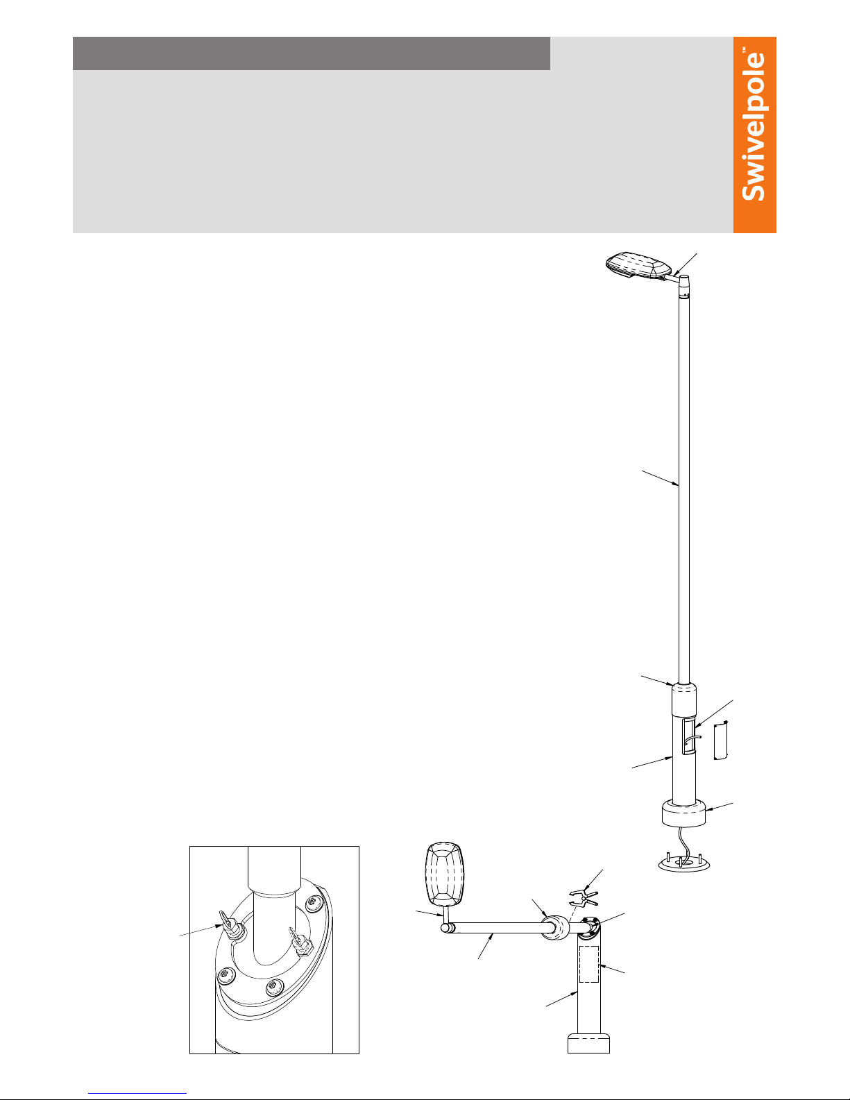
1. Feed the electrical cable
through the base section of the
Swivelpole™ to the access panel.
2. Position the base section over
the installed cage bolts.
3. Rotate the Swivelpole™
base section to the desired
orientation.
4. Align the base section so it is
vertical.
5. Tighten base plate bolts.
6. Slide the base cowling over the
base pole to cover the base plate.
7. Feed the electrical cable through
the pole top prior to bolting to
the swivel plate.
8. Apply multi-purpose grease to
swivel plate surfaces and bolts.
9. Slide the clamp plate onto the
pole top.
10. With one person holding the
pole top horizontally, the second
person can position the round
swivel plate locator into the hole
of the base section swivel plate.
11. Bolt the clamp plate to the swivel
plate, using the fastening kits.
Refer to Figure 1: For lowering
direction preference.
12. Tighten the bolts evenly.
13. Apply enough tension to allow
controlled raising of the pole top,
at this point the Swivelpole™ will
be self supporting.
14. To raise, use two people to guide
it as it swivels to the upright
position.
15. Insert the safety pin.
16. With the pole top in the upright
position, mark the pole in the
direction the xture is to face,
and lower it again to t the
xture.
17. Slide the joint cowling onto the
pole top using a spring clamp to
keep the joint accessible.
18. To lower, retract the safety pin
and swivel the pole top down to
a safe working height and insert
the safety pin.
19. Fit the xture mount as per
marked position on pole top.
20. Tighten the grub screws to a
torque setting of 17Nm to 20Nm.
21. Complete installation and
termination of the xture.
22. Raise the Swivelpole™ and insert
the safety pin. Tighten the
bolts evenly to a torque setting
between 40Nm and 80Nm.
23. Lower the cowling over the joint
and tighten the tamper proof
screw.
Installation of Swivelpole™ F19
SP-IEC-Installation Guide F19-20180830
Figure 1
AS SHOWN FOR
R/Hand LOWERING
DEPENDING ON SITE
CONDITIONS CLAMP
PLATE AND STOP TAB
PLUNGER CAN BE
INSTALLED ON THE
OPPOSITE SIDE TO
ALLOW FOR L/Hand
LOWERING
F19 - CPST (CLAMP-STOP TAB) - Installation Guide View
AS SHOWN FOR
R/Hand LOWERING
DEPENDING ON SITE
CONDITIONS CLAMP
PLATE AND STOP TAB
SAFETY PIN CAN BE
INSTALLED ON THE OP-
POSITE SIDE TO ALLOW
FOR L/Hand LOWERING
F19 Installation Guide - Views
Base
Access
Cowling
INSTALLATION
Mount
Joint
Luminaire
Panel
Pole Top
Base
Cowling
Luminaire
OPERATION
Base
Joint
Panel
Access
Cowling
Pole Top
Joint
Mount
Spring
Clamp
F19 Installation Guide - Views
(not
supplied)

Product warranty. All equipment and goods are warranted by the seller to be free from defects in
material and workmanship for ve (5) years from the date of shipment. This warranty does not apply
to equipment or goods which are misused, abused, or damaged, or not used in accordance with
seller’s instructions. Normal wear of equipment or goods are excluded in this warranty. No warranty
shall apply or responsibility will be taken for any modications, alterations or additions to the standard
product design. This includes exceeding recommended maximum weights for any ttings or exceeding
the installed height.
Equipment or goods not manufactured by the seller but supplied through the seller shall carry the
warranty of the original manufacturer. The seller’s sole liability under this warranty shall be limited
to either replacing or repairing without charge, at its factory or elsewhere at its discretion, any
equipment or goods not meeting this warranty, or at seller’s option, refunding the purchase price. The
seller shall in no event be liable for any other direct, indirect or consequential losses or damages of
any kind under this contract or otherwise.
Optional material nish of Powder Coating is completed by third parties and whilst all care is taken by
Swivelpole™, warranty is limited to the (12) months Supplier’s standard warranty. This warranty does
not apply to equipment or goods which are misused, abused or damaged or not used in accordance
with seller’s instructions. Normal wear of equipment or goods are excluded in this warranty. All care
should be taken for the longevity of the powder coat nish.
*Subject to change without notice.
Patented. Swivelpole™ products are manufactured under licence.
Patents include US patent No. 6957832 and Australian patent No. 767949
Operation and Safety Information
These guides are to be followed in conjunction with your worksite
procedures, safety rules and regulations.
Customer Service
Swivelpole™
Email: [email protected]
swivelpole.com
INSTALLATION & OPERATION GUIDE
The patented Swivelpole™allows controlled lowering of the pole into a
safe and comfortable working position. This guide should be followed to
ensure the Swivelpole™ product is assembled and installed safely and
correctly so it works to its optimum performance.
Copies of general assembly drawings are available online
www.swivelpole.com
To lower Swivelpole™:
1. Slide the joint cowling up the pole and use a
spring clamp to hold in place.
2. Ensure safety pin is inserted.
3. Loosen - but do not remove - bolts so the top
section lowers with some resistance on the
clamping plate. This allows safe and controlled
lowering action for two-person operation.
4. Whilst holding the pole top with one hand,
retract the safety pin and lower
it to a comfortable working position.
5. Insert the safety pin.
To raise Swivelpole™:
1. Retract the safety pin.
2. Push the pole top, guiding it as it
swivels to the upright position.
3. Insert the safety pin.
4. Tighten the bolts evenly to a torque
setting of between 40Nm and 80Nm.
5. Lower the cowling over the joint and
tighten the tamper proof screw.
F19 Orientation
Tools and materials required for
Swivelpole™ assembly:
• A torque wrench.
• Spring Clamp.
• Allen keys to suit: M8 grub screws -
use for light mounts.
• Multi-purpose grease for Safe Swivel™
joint.
Maintenance and inspection
• Visually check the Swivelpole™ for any
signs of damage and report ndings.
Table of contents
Popular Outdoor Light manuals by other brands

SLV
SLV ADJUST GU10 operating manual

Lightronics
Lightronics PKA installation instructions

iGuzzini
iGuzzini MAXIWOODY COMPACT owner's manual

HEISSNER
HEISSNER L426-00 Instructions for use

Home Decorators Collection
Home Decorators Collection HD-1200-LED Use and care guide

LIGMAN
LIGMAN LI-21321-LC installation manual