Sylvac D200S User manual

Unité multiplexeur pour palpeurs capacitifs Sylvac
Multiplexer-Einheit für kapazitive Messtaster Sylvac
Multiplexer unit for Sylvac Capacitive probes
D200S
MANUEL D’UTILISATION
GEBRAUCHSANLEITUNG
OPERATING INSTRUCTIONS
1

75
E
Contents
1Precautions..................................................................................................... 76
1.1 Important information ..................................................................................... 76
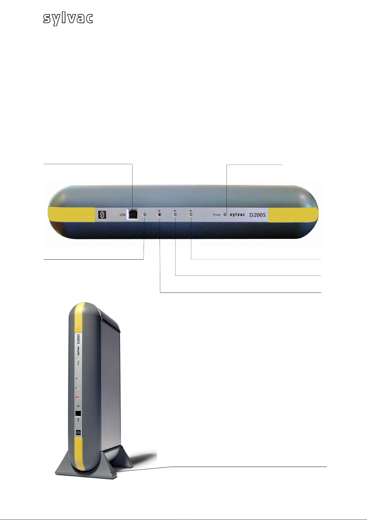
2General description of D200S unit................................................................ 77
2.1 Front of unit.................................................................................................... 77
2.2 Rear of unit .................................................................................................... 78
2.3 Functions of connectors (rear panel) ............................................................. 78
3Software D200S .............................................................................................. 81
3.1 Description of Software D200S ...................................................................... 81
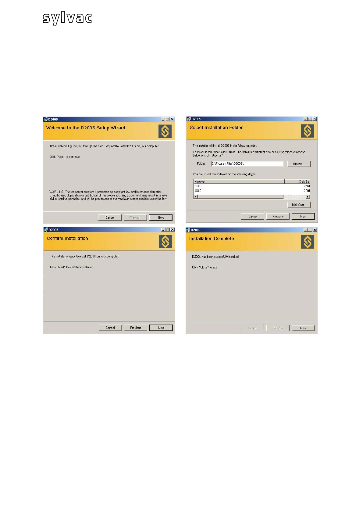
3.2 Installation of software D200S ....................................................................... 82
3.3 Hardware Connection between D200S unit and PC ...................................... 83
3.4 Installation of USB pilot.................................................................................. 83
3.5 Checking of Frontal LED indicators................................................................ 84
3.6 Connection (software) with D200S unit.......................................................... 85
4Use of software D200S .................................................................................. 86
4.1 The Main Menu .............................................................................................. 86
4.1.1 Sub-menu RS232 Setup........................................................................ 87
4.1.2 Sub-menu Channel Setup ..................................................................... 88
4.1.3 Sub-menu Sequences Configuration..................................................... 89
4.1.4 Sub-menu Foot Pedal, Switch 1 and 2 Setting ...................................... 90
4.1.5 Sub-menu Digital Output ....................................................................... 91
4.1.6 Sub-menu Simulation Mode .................................................................. 92
4.1.7 Sub-menu Send to................................................................................. 93
4.1.8 Sub-menu Open File ............................................................................. 95
4.1.9 Sub-menu Save As… ............................................................................ 95
4.1.10 Open Configuration (from D200S) ......................................................... 95
4.1.11 Transfer (to D200S)............................................................................... 96
4.1.12 Transfer + Save (to D200S)................................................................... 96
4.1.13 Reset unit .............................................................................................. 96
5Functions of the basic screen....................................................................... 97
5.1 Standard Mode .............................................................................................. 97
5.2 Bargraph Mode .............................................................................................. 98
5.3 Example of measurement with two points of measurement (2 probes).......... 99
5.4 Example of measurement with four points of measurement (4 probes) with
two D200S units............................................................................................101
6Communication protocol (remote commands)..........................................103
6.1 Example of communication with software Winwedge 32...............................103
6.2 Code for remote commands..........................................................................104
7Calibration of the unit ...................................................................................107
8Technical specifications...............................................................................108
9Sizes............................................................................Erreur ! Signet non défini.
10 Delivery ..........................................................................................................109
11 Optional accessories ....................................................................................109

76
E
1 Precautions
CAUTION:
- Never expose the D200S unit to water or moisture.
- Never use the D200S unit outside.
- Use the D200S unit at a temperature between 0 and 40°C.
- The manufacturer declines all responsibility in case of damage
due to an inappropriate use of the D200S unit.
- Not to use aggressive products (Alcohol, trichloroethylene, etc.) to
clean the synthetic parts.
1.1 Important information
Minimum configuration Hardware
Pentium processor or equivalent.
(Pentium 600 MHz or higher is recommended).
A computer functioning under Windows 2000 or Windows XP operating system.
Stability of the unit :
The D200S unit must be switch ON ~30 minutes before all measurements.

77
E
2 General description of D200S unit
The D200S acquisition unit is a unit being able to read up to 8 probes Sylvac P2, P5,
P10, P25, P50 with a maximum resolution of 0.1 µm and that in a dynamic mode.
Many integrated functions make it possible to solve the majority of the measurements
problems in workshop or laboratory. The parameters introduced into the software can
be saved into the D200S unit. Several units can be coupled in order to connect up to
24 probes.
2.1 Front of unit
USB Connection Power supply indicator
Indicator of USB transmission
Indicator of general tolerances (=)
Indicator of general tolerances (<)
Indicator of general tolerances (>)
The unit can be positioned vertically using the two
supports feet.

78
E
2.2 Rear of unit
2.3 Functions of connectors (rear panel)
ON / OFF switch
Pin 1 Ground
Pin 2 Input + 9 V
Pin 3 External contact input, signal = 0 Volt
Pin 1 Ground
Pin 2 Input + 9 V
Pin 3 External contact input, signal = 0 Volt
USB connector
Probes input RS232 connector
Digital output connector
Socket for charging unit
Socket for external contact
ON / OFF Switch

79
E
Not used
Pin 1
TXD = input RS 232 C
Pin 2
RXD = output RS 232 C
Pin 3
Not used
Pin 4
SG = Signal ground
Pin 5
Not used
Pin 6
Not used
Pin 7
Not used
Pin 8
Not used
Pin 9
N° Configuration 1 Configuration 2
Channel Tol Master Tol & D110
14 Tolerance channel 1 Tolerance >
Tolerance channel 213 Tolerance =
Tolerance channel 312 Tolerance <
Tolerance channel 411
Tolerance channel 510 Lifting command D110
Tolerance channel 69 Lifting command D110
Tolerance channel 78 Lowering command D110
Tolerance channel 87 Lowering command D110
6 Common Common
5 +5V +5V
Pins 7 to 14 : Opto-couplers output for signal or pneumatic controls (D110)
according to the mode used.
Comment : In "Channel Tol" mode, the pins 7 to 14 are active when the
measurement of the corresponding channel is out of tolerances.
4 +9 V +9V
3 Switch 1 Switch 1
2 Switch 2 Switch 2
1 GNDD GNDD

80
E
Pin 6 : Common for 8 opto-coupler outputs
Pin 5 : Output + 5V / 100 mA , non-regulated (protected)
Pin 4 : Output + 9V / 200 mA , non-regulated (protected)
Pins 2 & 3 : Input for external contact
Use only one tension of 5V on these inputs.
Max voltage = 30V and the
max current is 60 mA per
output.
The opto-coupler outputs
must be supplies
externally with negative
voltage to common
emitters (pin 6)
The protection diode is
necessary in case of
inductive charge (electro-
valve, relay, solenoid…)
Example of connection for Switch 2
Pins 2/3
Pin 5 (5V)

81
E
3 Software D200S
3.1 Description of Software D200S
The Software D200S is used like an interface between the D200S unit and the user.
The use of the software makes it possible to read the values of the probes and
configure the unit for the autonomous mode. All the parameters are saved when
stopping the software.
It is possible to use unit D200S and software D200S in two different ways.
1. The software can be used to
D200S unit can only be used (without connection and software)
memorize the control parameters, then the
2. The software can be used on line with the D200S unit, which will make it
possible to follow measurements to the screen, as well as the bargraph of the
individual values.

82
E
.2 Installation of software D200S
npack the CD of installation and introduce it into the CD reader of the PC.
elect the CD reader directory for installation, then Setup.msi file and double click on
.
ollow the instructions on the PC.
3
U
S
it
F

83
E
.3 Hardware Connection between D200S unit and PC
port of your PC with USB
3
4
3
1) Switch ON your PC.
2) Connect the USB plug of the D200S to the USB
cable.
) Connect the probes to the Tuchel connectors of the D200S unit.
) Connect if necessary the digital outputs.
5) Connect the sector adapter to the socket 9V of the D200S unit.
Caution : Use the sector adapter provided exclusively.
The use of an erroneous sector adapter can damage the D200S unit.
6) Connect the sector adapter to the main power.
7
install the necessary pilots.
) Switch ON the D200S unit then the 3 led's of tolerances flicker during a short
moment and the PC detects the D200S unit automatically.
3.4 Installation of USB pilot
As soon as the PC detected the D200S unit, follow the requests on the screen to
Windows XP
he Add assistant of material appears on the screen
sers) and click on Next.
the files of the pilots necessary.
he place of the pilot file is: D:\Drivers\WindowsXP, if your CD reader of CD has the
nce that the nt o d the results of research, click on Next to
all the nec pilot
essa not fou n,
continue the
e assistant o esearch for new materials finished the installations,
Finis
) Continue by "Checking of frontal LED indicators "
T
A) Select Install from specific directory (experienced u
B) Select CD-Reader and click on Next to search
T
letter D. If not, indicate the valid letter of your system.
C) O assista f material fun
inst essary files.
Note: if the m ge “ nd the numerical Signature” appears on the scree
click on "Yes" to installation.
D) Once that th f r
click on " h".
E) If the update of assistant of material appear again. The points A, B, C and D
should be carried out a second time.
F

84
E
.5 Checking of Frontal LED indicators
e ON permanently. If it is not
e case, switch OFF theD200S unit, wait 10 seconds and switch ON the unit again.
D Colour Description
3
After the complete installation, the "LED" power should b
th
LE
Power green the D200S unit is connected to the sector and ready.
Activities USB
green Indicate that the data are received / transmitted via
USB connection.
Tolerances
global status <
red Indicate that measurements are out of tolerance
(not re-workable)
Tolerances
global status =
green Indicate that measurement are in tolerance (good)
Tolerances
global status >
yellow Indicate that measurements are out of tolerance
(re-workable)
Note: The "LED" "Activities USB" flickers only when data are sent or received via the
USB connection, it does not flicker if via the RS232 cable.
nce that all is installed correctly, start the application.O
The following window appears:
The configurations introduced after the first use are saved to each exit of the
software, thus the user finds the program in the same status after each use.

85
E
.6
order to connect the software with the D200S unit, click on the activation icon to
nable the software and the unit.
ait until the message. « Waiting for synchronisation… » disappears.
3 Connection (software) with D200S unit
In
e
W
Note: the port of communication g
(in the gray zone) then by select
The port number allocated by W pening the peripheral
managers ("control panel /syste "peripheral managers
"). The D200S appears as "a USB Serial Port". Each D200S connected to the PC will
have a COM port which will be a
Enables/Disables the
communication between the
unit D200S
can be configured in the software by a right clickin
ing "RS232 Setup".
indows can be visualized by o
m" then select "material" and
llocated for it.
software and

86
E
of software D200S4 Use
4.1 The Main Menu
Access to the sub-menu
e mouse in the gray zone (out
whole of your personal data.
f
This sub-menu allows selecting the parameters of
This sub-menu allows selecting the programming
nt channels.
-menu allows selecting the function of the
external contact (foot-pedal).
witch 1 Setting
his sub-menu allows you to choose h 1 (Digital output
onnector)
witch 2 Setting
his sub-menu allows you to choose tput
onnector)
igital Output Setting
his sub-menu allows you to select th
ol&D110 or Channel Tol.)
imulation Mode
his mode allows to simulate the ex and to visualize the status of the
igital outputs.
end to
his sub-menu allows selecting the d
rograms (Excel...)
pen File
his sub-menu allows you to open a
ave As…
his sub-menu allows you to save a
pen Configuration (From D200S)
his sub-menu allows you to activate
ransfer (to D200S)
his sub-menu allows you to transm
e D200S unit.
ransfer + Save (to D200S)
his sub-menu allows you to transmi
e D200S unit.
eset Unit
his sub-menu reinitializes the D200S
Click the right key of th
of the displayed values). The main menu allows you
to configure the
RS232 Setup
This sub-menu allows to select the parameters o
RS232 (Ports.COM..)
Channel Setup
measurements per channel.
Sequences Configuration
mode of several sequences of measurements by
using differe
Foot Pedal Setting
This sub
S
T the function of Switc
c
S
T the function of Switch 2 (Digital ou
c
D
T e mode of measurement to be used. (Master
ternal contacts
T
S
T
d
S
T estination of the data to various software
p
O
T saved file (* syl)
S
T file (* syl)
O
T the saved configuration in the D200S unit.
it temporarily the configuration of the software in
T
T
th
T
T t and save the configuration of the software in
unit.
th
R
T

87
E
.1.1 Sub-menu RS232 Setup
RS 232 Setup
4
The Parameters of transmission are:
Baud Rate : 19200
Data Bits : 8
Parity : N (None)
Stop Bits : 2
They are automatically selected.
The Configuration RS232 or USB allows you to
select the port or the ports used. One unit = 1
port (COM...)
The end Characters of transmissions can be
configured on : TAB, ENTER, Up arrow,
arrow
function of Record Preamble Keystrokes
w, Left Arrow.
y, select the
he frequency of
y three seconds
click the
ct the second port
for use of a third D200S unit.
Down
heT
can be configured on :
NTER, Up Arrow, Down ArroE
Automatic data request (Scanning)
To collect the data automaticall
tappendix in white, than select
measurement (for example: ever
(3000 ms)
tion,To select a second connec
appendix in white, than sele
used.
Idem

E
4.1.2 Sub-menu Channel Setup
Configuration of the channels
following parameters:
Each channel can be configured with the
Setting :
Upper Tol. = Upper tolerance
Lower Tol.. =Lower tolerance
Nominal Value = Nominal value
g direction and mode
Preset Value = Pre-selected value
Measurin
Increase (+) = positive (+)
Decrease (-) = negative (-)
Measuring type: External or Internal
Measuring mode :
Direct: direct display of the value
Max: displays the maximum value
Min: displays the minimum value
Delta: displays the difference (maximum - minimum)
um) of all channels,
preceding the channel in
e. g.: the "Flatness" mo
is connected to th
maximum-minimu
displayed on channel 6. The utmost maximum and the smallest
minimum of chan
corresponds to a general "delta" of the channels 1 to 5.
Comment: the "Flatnes
the time.
oncentricity: displays the difference (
omment: after configuration of the m ssary to press the
"Min/Max" key to activate the function. If not, all channels will stay in
direct mode.
hannel disable :
Mean: displays the mean value (maximum + minimum)/2
Flatness: displays the difference (maximum - minim
dicating the "Flatness" mode.
de has been selected on channel 6 (no probe
is channel). In this case, the difference of
m of channels 1 to 5 will be calculated and
nels 1 to 5 are used for calculation. This
s" mode must only be used on 1 channel at
maximum - minimum), identical to a "delta".
easuring mode, it is nece
C
C
C
he channel selected can be hidden, th value is not visible anymore but the
easurement is always active.
alibration :
T e
m
C
ach channel can be calibrated individ r 7.
ef 0 : Reference value 0
ef 1 : Reference value 1
ath. function
E ually. See chapte
R
R
M
actor A : multiplication factor of the ch nnel.
anal A : Selected channel(1, 2 ,…)
measurement can be made up of se ade
y an operator (+,-,*,/).
alibration Dates
F a
C
A
b
veral channels, the combination can be m
C
he calibration date can be introduced
he next calibration date can be introd
eset :
T .
uced.T
R
rase all the data of the selected chanE nel.
88

89
E
4.1.3 Sub-menu Sequences Configuration
Configuration of the measuring sequences
This configuration allows the assignment of a
certain number of channels to a sequence,
in order to send on Excel (or other), that values
introduced for a sequence given.
It is possible to configure up to 8 sequences.
* The use of the preset and the send are affected
by the configuration of the sequences, by default
only the sequence I is activated and all the
channels are selected.
Example :
1st sequence (I), channel 1 is selected.
The data acquisition on (Excel) will be, for each
transmission.
Send the value
el 1)
0.001
2 s
0.001(1st sequence) (Chann
Send again
1st sequence) (Channel 1)
equences
1st sequence (I), channel 1 is selected.
2nd sequence (II) channel 2,3 are selected.
The data acquisition on (Excel) will be, for 1st
tra
0.0 ence) (Channel 1)
2nd ission
0.0 l 2)
0.0 sequence) (Channel 3)
Send again :
0.0 annel 1)
Th
0.003 (2nd sequence) (Channel 2)
0.004 (2nd sequence) (Channel 3)
In the automatic mode, the sequences are
nsmission.
01 (1st sequ
transm
03 (2nd sequence) (Channe
04 (2nd
01 (1st sequence) (Ch
en :
*Automatic data request
automatically sent one after the other.

90
E
-menu Foot Pedal, Switch 1 and 2 Setting
Single Function
e attribution of a single function to
the external contact
Function
Allows the attribution of multiple functions
t. It is possible to
Activates the "Preset" value
Initializes Min/Max…
o
ctivates the downwards movement of the probes (by the unit D110).
D110 Lifting
Activates the upwards movement of the prob
D110 Toggle
Activates the upwards/downwards movement of the probes (by the unit D110).
Hold Enable
Activates the inhibition of values. The values displayed are locked; the movement of
the probes has no effect on the displayed values anymore.
Hold Disable
Deactivates the inhibition of values.
ause Enable
ctivates the "Pause" function (see also page 97)
ause Disable
eactivates the "Pause" function (see also page 97)
Pause Toggle
Activates / deactivates the "Pause" function (see also page 97)
Print – Seq1-8
Sends the selected sequence to Excel / Notepad. The sequences may be configured
in menu "4.1.3 Sub-menu Sequences Configuration"
Change Digital Output Setting
Two modes are possible in the configuration menu for the Digital Output:
1 = Master Tol & D110,
2 = Channel Tol,
By activating the external contact, this configuration changes from one to the other
function. See chapter 4.1.5
4.1.4 Sub
Allows th
Combined
to the external contac
combine up to 4 functions.
No Function
No function
Print
Activates the data transfer
Preset
Clear
D
A
110 L wering
es (by the unit D110).
Hold Toggle
Activates / deactivates the inhibition of the values.
P
A
P
D

91
E
Digital Output
4.1.5 Sub-menu Digital Output
This menu allows modif
configuration of the digital outputs
according to 2 functionin
Master Tol & D110
or
Channel Tol
figuration, the digital Output functions will be modified according
table page 79
ying the
g modes:
According to the con
to

92
E
ion Mode"
his menu allows the simulation of the digital outputs and the external contacts.
4.1.6 Sub-menu "Simulat
T
The actions of the external
contacts and the switches
1/2 are saved in a file
(saved in installation
program)
Shows the saved file Simulates an action on the
co
n
ce
rn
ed
co
n
tact
Activates successively the
hose offrontal LED's and t
the digital outputs
The active digital outputs are
mentioned in
g
reen
Indicates the configuration
of the digital outputs
(Master Tol or Channel Tol)
Description of the "Log" file
Indicates the config. of the digital outputs:
Master Tol 0 : Channel Tol
ol 1 : Master TolMaster T
Indicates the active Date and time of the
measured valuedigital output
In
S
dicates used channel
witch n°1 : foot pedal
witch n°2 : switch 1
witch n°3 : switch 2
S
S
P d function:
NO_FCT : no function
Print : activates the data transfer
Preset : activates the "Preset" value setting
Clear : initializes the min, max, ... values
D110 D : activates the downward move.of probes (D110)
D110 U : activates the upwards move. of probes (D110)
D110 T : activates upw./downw. move.of probes (D110)
Hold g : activates lock-in of values
Hold i : deactivates lock-in of values
H
P
P
P
P
according to menu "sequence configuration"
DIGOUT : changes the configuration of the digital outputs
erforme
old j : activates/deactivates the lock-in of values
ause h : activates the "Pause" function
ause k : deactivates the "Pause" function
ause l : activates/deactivates the "Pause" function
RISEQx : sends the values of the channels selected
Indicates the unit used for
activation of the contact:
Unit n°0 : first unit
Unit n°1 : second unit
Unit n°2 : third unit

93
E
ub-menu Send to
Send to
4.1.7 S
The function "Send to" allows sending the
values directly to:
- Excel
- Notepad
or to save them in an Excel or Notepad file
without opening the addition of:
- .txt File
- .xls File
A window opens during the first transmission
values, it makes it possible to reach the
function "send" even the software is not
visible.
The option "Set window on top" makes it
possible to send the values in Excel/Notepad
hile keeping software D200S to the foreground.
h
nd the number of the part to Excel / Notepad before sending the measured values.
he option "Reset Piece Number" resets the numbering of the parts to zero.
. Click the Send icon
An Excel sheet will open, as well as the icon Send.
Click on the icon Send, the selected values will be displayed on the Excel sheet.
w
T e option "Print Time & Date / Piece Number" allows sending the date, the time
a
T
Excel
1. Select Excel
2
Other manuals for D200S
1
Table of contents
Popular Industrial Equipment manuals by other brands

Kremlin-Rexson
Kremlin-Rexson CYCLOMIX MICRO+ instruction manual

Emerson
Emerson SolaHD SCM-W-HRT7 user guide

Agilent Technologies
Agilent Technologies E444 AU Series installation guide

Siemens
Siemens SIRIUS 3RB29 6-2 Series operating instructions

Toro
Toro Workman 07224-90001 Operator's, Set-up, and Parts Catalog

Syncronorm
Syncronorm SyncroSwitch operating manual