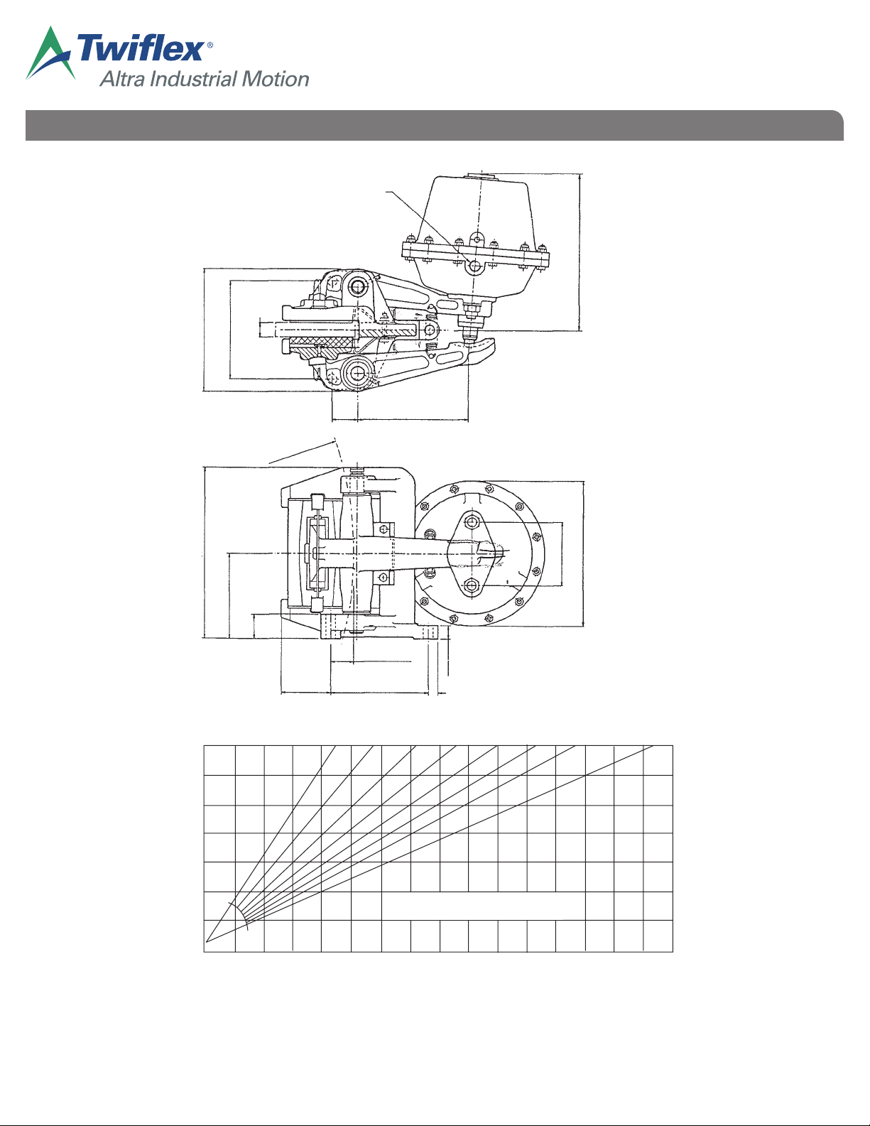
GMR-S and GMR40-S Disc Brake Caliper - Spring Applied, Air Released
N.B. Keep fingers clear of the space between push rod and caliper arm at all times.
If an inclined mounting kit is fitted, the stop screw should be re-adjusted to maintain equal pad clearance
on either side of the disc.
2.5 Pad wear can be monitored by observing the gap between the lugs on the pads pressure plates and the
machined surfaces on the caliper frame, when the brake is applied. Pads must be replaced {see 3.2)
before the gap is reduced to zero. The maximum allowable wear on a pad is 10mm).
3. Maintenance
CALIPER
3.1 Ensure that the brake pad and disc remain tree from oil and grease. Clean the disc as require. If the pads
become contaminated they should be replaced. Carry out any periodic statutory testing that is required,
or otherwise check for satisfactory performance.
3.2 Pad replacement is carried out from the rear of the caliper; DO NOT release the spring clips which attach
the pressure plates to the caliper arms. With the brake off (retraction screw may be fitted as a safety
screw) remove the caliper return springs and the keep plates. If an inclined mounting kit is fitted, remove
this also. Withdraw the pads to the rear and lift out. (The hole in the end of the pad retaining plates is
provided to assist in withdrawing the pads). Fit the new pads (part number 7080080), ensuring that the
slotted retaining plate is located around the keep disc on the pressure plate; the pads should slide freely
into position. Replace remaining parts. Re-adjust the push rod, as in (2.4), and the stop screw if fitted.
3.3 The surface of the caliper arm on which the thruster pushrod bears should be kept well greased. The
knuckle joints between the caliper arms and the pressure plates should be cleaned occasionally, and a
small amount of grease applied; the joints may be levered apart slightly against the pressure of the
spring clip. Occasionally, or if caliper is not operating freely, inject a small amount of grease via grease·
nipples to lubricate the pivot pins, then rotate pins to distribute the grease. Any grease exuding past the
‘0’-rings should be wiped off. The pins may be turned by gripping the knurled end at the top of the
caliper.
After extended one million operations or three years) use, the pivot pins should be withdrawn, cleaned,
replaced and regreased, or replaced if badly worn.
In order not to damage the 0-ring seals on the pins, use the following procedure. Remove the top circlip,
push pin down until the lower circlip and ‘0’-ring can be removed, then withdraw the pin upwards. To
refit, reverse this procedure.
THRUSTER
3.4 Clean the push rod as required. If the air supply is wet, the drain plug (23) should be removed at intervals
to release any accumulated water.
In the event of leakage or malfunction of the thruster, the following parts can be inspected and replaced if
necessary, using the procedures described below, without decompressing the spring pack:-
Diaphragm (15)
Rod Seal (9)
Bush (30)
Wiper Seal (7)
Push rod (8)
3.5 Replacement of any other component, i.e. 0-rings (12), (13), bush (31) and springs requires the spring
pack to be decompressed. This is not covered in these instructions, and should only be carried out by
Twiflex or their agents. If the pushrod is known to be damaged, replace it first, as in 3.11. Otherwise
proceed as below.
WARNING:- DO NOT ATIEMPT TO DECOMPRESS THE SPRINGS BY UNSCREWING THE RETRACTION SCREW.
Thruster Servicing
3.6 With the brake ott, insert retraction screw and screw it fully in; finger tight is sufficient. (If thruster will not
retract, the brake should be released using the retraction screw, which should be well lubricated).
Disconnect the air supply and remove thruster from caliper.
Adjust the retraction screw to allow a thruster stroke of approximately 32mm (i.e. just under full stroke).
This adjustment allows the diaphragm to assume its natural shape, which eases re-assembly. The use of
a temporary air supply will be found convenient, as it avoids having to turn the retraction screw under
load.
Withdraw the bolts (21), and remove the front cap (1), spring ring (17), support plate (16) and diaphragm
(15). The diaphragm should be free from splits of cracks, but some wear from the edge of the spring plate
(11) is acceptable if the fabric reinforcement is not damaged.