ruptedtoinsertaccessoryequipment.Forexample,
anenvironmentalequalizermaybeusedtoshape
frequencyresponsetosuitroomacoustics.Alter-
natively,thePRE-AMPoutputmayberoutedtoan
electroniccross-overnetwork.Thelowfrequency
outputofthisnetworkwouldbeconnectedtothe
powerAMPinputwhilethehighfrequencyoutput
shouldbeconnectedtoa separateslavepower
amplifier.Finally,thePRE-AMPoutputcouldbe
usedtodrivea slavepoweramplifierlocatedre-
motelyfromthereceiver.
NOTE:Tousebothslaveampandtheinternal
poweramp,DONOTusethemainhighlevel
slaveampoutputtofeedthereceiverpower
amp.
Eitherusetheslaveamplowlevelout-
putorusea commerciallyavailable"Y"
connectoratthereceiverPRE-AMPjacks.
Onesideofthe"Y"goestotheaccessory
input,theothergoestotheAMPjacksofthe
receiver.
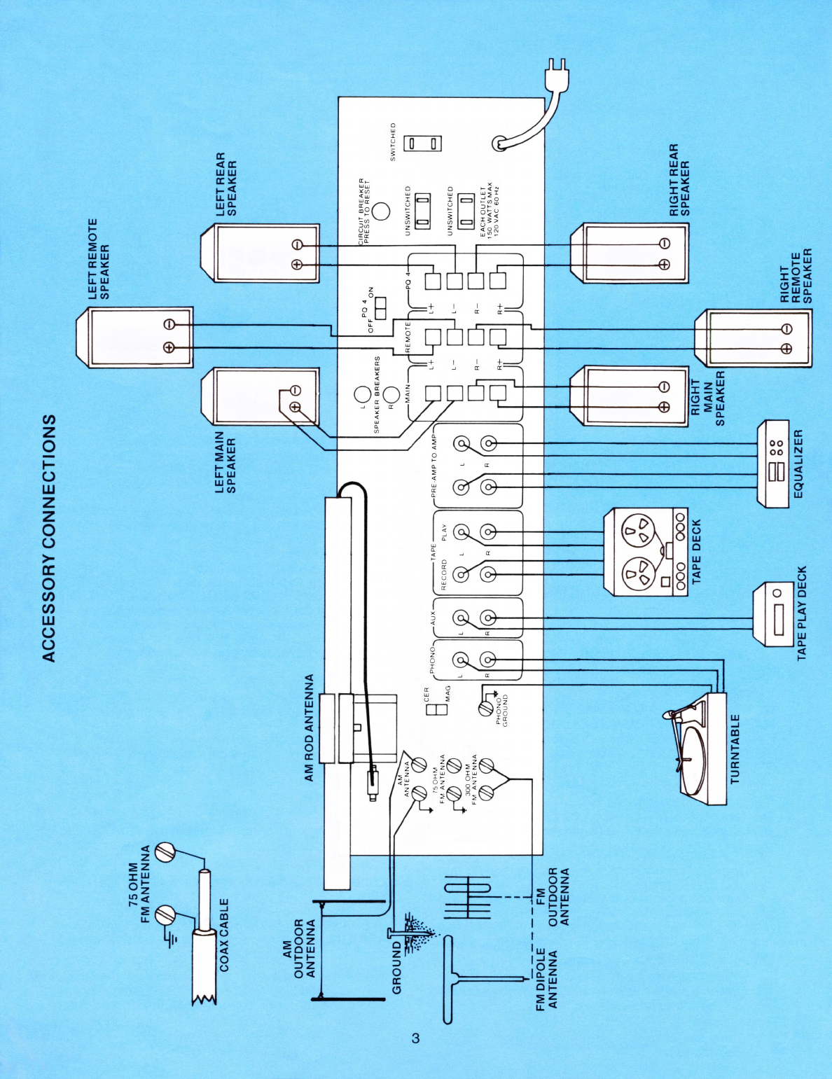
Speaker
Connection(N)
Usenosmallerthan18gaugewiretoconnect
speakerstooutputterminals(N).Alwaysbesure
positiveandnegativeoutputsareconnectedto
correspondingpositiveandnegativeterminalson
thespeaker.
MAIN
Connecttheprimarypairofspeakerstothemain
terminals.
REMOTE
Connecta secondarypairofspeakerstotheremote
speakerterminals.Thesespeakerscouldbelocated
inanotherroom.
PQ-4
Connecta pairofrearchannelspeakerstoobtaina
fourchannelmatrixsound.Switch(G)canbeused
toturnoffrearspeakerswhennotinuse.
Unswitched
AC
Outlets
(I)
Plugaccessorycomponentssuchasturntablesor
tapedecksintotheseoutlets.Theseoutletsremain
onwhenthereceiverpowerswitchisturnedoff.
Switched
AC
Outlet
(J)
Plugassociatedelectroniccomponentssuchasan
environmentalequalizerorslaveamplifierintothis
outlet.Thisoutletwillbeoffwhenthereceiver
powerisoff.
NOTE:
Donotusethisoutletforturntables,tape
decksorothermotordrivenaccessories.
PROTECTIVECIRCUITS
Yourreceiverincorporatesthreeprotectivesys-
temstoguardagainstabnormaloperatingcondi-
tionsthatcouldcausedamagetothereceiveror
speakers.
Electronic
Current
Limiting
Protectstheamplifierfromimproperlyconnected
speakers.Iftheoutputisshortedorexcessively
loaded,
theamplifierwillautomaticallyreducethe
outputsignaltosafelevels.
Circuit
Breaker
—
Main
(H)
ProvidesprotectionagainstACpoweroverloads.
Ifyourunitsuddenlygoesoff,pushthebutton(H)
intore-setthebreaker.Donotholdthebuttonde-
pressedforanextendedlengthoftime.Iffrequent
resettingisrequiredconsultyourauthorizedSyl-
vaniaservicedealer.
Circuit
Breaker
—
Speakers
(F)
TherearetwoSPEAKERBREAKERS,onefor
eachchannel.Thesebreakerswillturnyourspeak-
ersoffautomaticallyincaseofanoverload.Turn
setoffandpushappropriatespeakerbreakerbut-
ton(F)in.Iffrequentresettingisrequiredcheck
speakerwiringforshorts,damagedspeakersor
overloadduetoimproperspeakerimpedance.
5