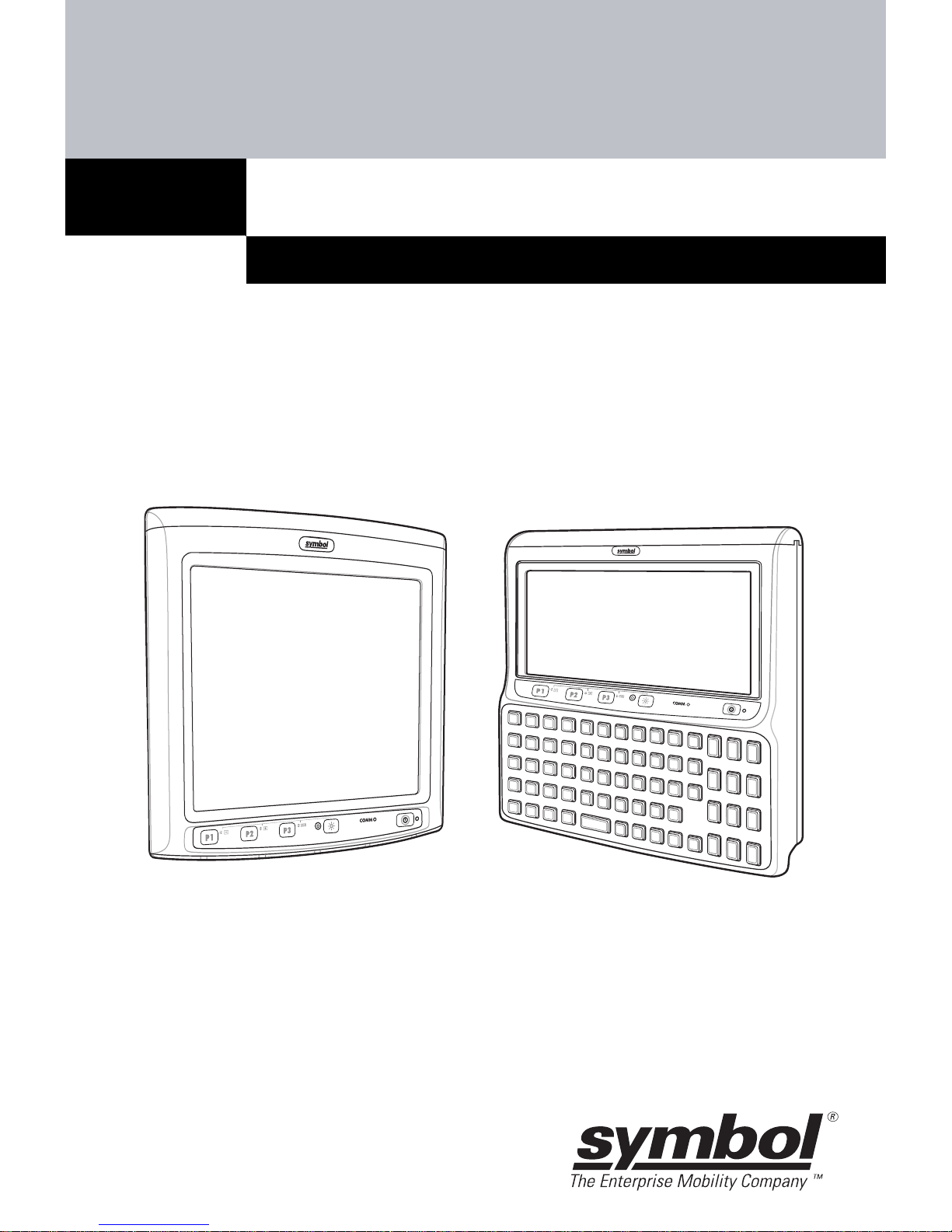
2 VC5090 Vehicle Computer
©2006 SYMBOL TECHNOLOGIES, INC. All rights reserved.
Symbol reserves the right to make changes to any product to improve
reliability, function, or design.
Symbol does not assume any product liability arising out of, or in
connection with, the application or use of any product, circuit, or
application described herein.
No license is granted, either expressly or by implication, estoppel, or
otherwise under any patent right or patent, covering or relating to any
combination, system, apparatus, machine, material, method, or process
in which Symbol products might be used. An implied license exists only
for equipment, circuits, and subsystems contained in Symbol products.
Symbol and the Symbol logo are registered trademarks of Symbol
Technologies, Inc. Other product names mentioned in this manual may
be trademarks or registered trademarks of their respective companies
and are hereby acknowledged.
Symbol Technologies, Inc.
One Symbol Plaza
Holtsville, N.Y. 11742-1300
http://www.symbol.com
Warranty
Subject to the terms of Symbol’s hardware warranty statement, the
VC5090 Vehicle Computer products are warranted against defects in
workmanship and materials for a period of one year from the date of
shipment. For the complete Symbol hardware product warranty
statement, go to: http://www.symbol.com/warranty.
Patents
This product is covered by one or more patents. For patent information
go to: http://www.symbol.com/patents.