manuals.online logo
Brands
  1. Home
  2. •
  3. Brands
  4. •
  5. Hyundai
  6. •
  7. Automobile Accessories
  8. •
  9. Hyundai CWF21 AU000 User manual

Hyundai CWF21 AU000 User manual

Genuine Accessories
Electronic Installation Instructions
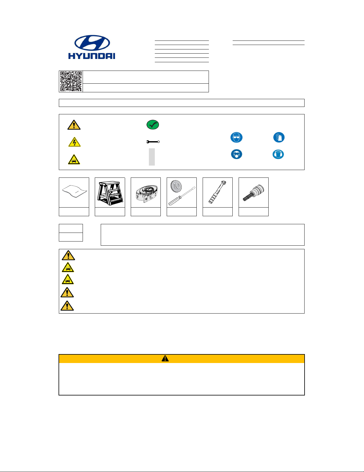
Glasses Gloves
Mask Hearing Protection
Part Weight (Gross) FMVSS 110 Compliance Information
1)
2)
3)
4)
5)
6)
• Evenly distribute the load
• Ensure the crossbars are secure.
• Precaution must be taken when operating vehicle's sunroof with crossbars and attachments installed.
WARNING
• Never exceed 165 lbs (75 kg) on top of crossbars.
Failure to adhere to load limits and distribution requirements may result in loss of vehicle control, severe personal injury, or death.
• Always check the height of the vehicle when crossbars and attachments are installed before driving under tunnels or parking
structures with low bridges.
NEVER place tools on painted surfaces, seating surfaces, dash pad, console or floor carpet/mats.
Always wear appropriate personal protective equipment, including gloves, safety glasses, etc., when required.
Clean Cloth Step Ladder Tape Measure
10.60
lbs All dealers must determine if the Net weight they have added in the form of all options or accessories, when added to the weight of all Port/Dealer Installed
options or accessories, exceeds the lesser of 1.5% of GVWR or 100 lbs. If the additional weight does exceed the lesser of the indicated thresholds, a “Load
Carrying Capacity Reduced” label must be installed. A black, fine-point, indelible marker must be used to write by hand onto the label, the reduced carrying
capacity in kilograms or pounds, which is the total weight of all added options and accessories.
Load Label Part Number: NP070 - 09003
4.80
kg
Notes to the installer:
Read the entire Installation Instructions prior to beginning the installation of this accessory.
If applicable, scan the barcode label located on the accessory part or packaging prior to installing, to register the part. If this accessory is installed as a replacement, register the removal of
the old part before registering the new part. Old and new parts will have different barcode data, and the old registration cannot be reused.
REGULARLY CHECK THE TIGHTNESS BY PERFORMING A TUG ON CROSSBARS.THEY SHOULD NOT MOVE.
If crossbars move, see step 3~5 for proper tightening. Incorrect clamp tightness can cause crossbar separation from vehicle resulting in
product failure and vehicle damage. Serious physical injury may occur.
Torque Wrench
Coin or Flat-Head
Screwdriver
Loads must be evenly distributed and secured. Failure to achieve the distribution requirements may result in loss of vehicle control, severe personal injury, or death.
Any weight carried on the vehicle will adversely affect its handling, particularly in cornering or in a cross wind and the vehicle should therefore be driven with increased caution.
Only use NON-STRETCH tie down straps. Use of stretch elastic tie downs may cause loss of load, potential serious injury, and vehicle damage.
Never exceed 165 LBS (75 KG) on top of crossbars. Failure to adhere to load limits may result in loss of vehicle control, severe personal injury, or death.
Make sure the vehicle is completely clean and dry in the area(s) the part is to be installed.
Ensure the vehicle is properly protected in the area(s) that the accessory is to be installed.
(B) Dealer Technician
(C) Master Technician or Specialist
If this is a printed copy of the installation instructions, ensure you have the latest revision by
scanning the QR code or by entering the website address listed below before beginning installation.
Use the latest revision date as noted by “Rev. Date” above.
www.hyundaiaccessories.com/admin_media_uploads/installationSheets/cwf21_au000.pdf
Instructional Symbols / Definitions
Denotes warnings that may lead to
serious physical injury or vehicle damage
Denotes quality processes to be checked
prior to moving to the next step
Denotes personal protective equipment (PPEs) that
may be required for a step. Examples of safety
equipment icons noted below:
Application Notes
Does NOT apply to models equipped with a Panoramic Roof
Denotes cautions to be taken to avoid
physical injury or electronic component
damage
Denotes specific tools that are necessary
to complete a step
N
O
T
E
Denotes important information to be
reviewed during the step
5mm Allen Socket
Denotes cautions to be taken to avoid
vehicle and component damage
Basic Required Tools
Copy OEM Logo Here (→)
Vehicle Model: Tucson Accessory: Crossbars
Difficulty stated above reflects the minimum level of
expertise required to install the accessory:
Language English
Model Year 2022~ Difficulty: ( A )
Part No. CWF21 AU000
Note:
Rev. Date 1/28/2021 (A) Customer
5560668001
Revision Date
01/28/2021 Page 1 of 6
Genuine Accessories
No. Qty
11
21
31
41
Service Part Overview
No. No.
1 4
2 5
3
Description
Top Cover Strip
End Cap Kit (Left & Right)
Lower Cover Strip Set
Service Part Number
CWF21 AU070
CWF21 AU060
CWF21 AU050
Qty
1
1
1
CWF21 AU030 Foot Cover
Service Part Number
CWF21 AU020
Description
Attachment Hardware Set
Kit Overview
Description
Rear Crossbar
Front Crossbar
1
Qty
Quick Reference Guide
1
Wrench
1
2
34
431/8"(109.54cm)‐ FullyExtended
455/8"(115.89cm)‐ FullyExtended
5560668001
Revision Date
01/28/2021 Page 2 of 6
Genuine Accessories
N
O
T
E
1
2 Wrench, Coin or Flat-Head Screwdriver
A. Clean the side roof rails in the areas shown.
Do NOT scratch or damage the vehicle.
A. Unlock all four (4) plastic cylinders by turning them counterclockwise as shown.
B. Carefully remove all four (4) foot covers as shown.
C. Set the four (4) foot covers aside in a safe location.
D. Loosen all four (4) bolts three (3) full turns using the provided wrench.
E. If vehicle is equipped WITH a Sunroof, skip to step 4.
N
O
T
E
Step Ladder and Clean Cloth
BOLT
5560668001
Revision Date
01/28/2021 Page 3 of 6
Genuine Accessories
4 Step Ladder and Tape Measure
N
O
T
E
A. Locate the front crossbar.
B. Verify the rounded profile of the crossbar faces forward for proper orientation as shown.
C. Carefully place the front crossbar onto the roof side rails. Ensure the crossbar brackets wrap around the roof rails as shown.
D. Position the front crossbars' foot front rubber edge 29" (740mm) from the forwardmost edge of the roof side rail on both sides of the vehicle as shown.
For Reference: The front crossbar is positioned 4" (100mm) rearward of the vehicle's B-pillar (door edge).
E. Locate the rear crossbar.
F. Verify the rounded profile of the crossbar faces forward for proper orientation as shown.
G. Carefully place the rear crossbar onto the roof side rails. Ensure the crossbar brackets wrap around the roof rails as shown.
H. Position the rear crossbars' foot front rubber edge between 27.6" (700mm) minimum and 33.5" (850mm) maximum from the edge of the front crossbars' foot forward rubber
edge on both sides of the vehicle as shown.
CAUTION: Placing the rear crossbar beyond 29.5" (750mm) from the front crossbar may affect vehicle antenna reception.
PIO Technicians Only: Position the rear crossbars' foot front rubber edge 29.5" (750mm) from the edge of the front crossbars' foot forward rubber edge on both sides of the
vehicle.
Do NOT scratch or damage the vehicle.
N
O
T
E
Do NOT scratch or damage the vehicle.
A. Locate the front crossbar.
B. Verify the rounded profile of the crossbar faces forward for proper orientation as shown.
C. Carefully place the front crossbar onto the roof side rails. Ensure the crossbar brackets wrap around the roof rails as shown.
D. Position the front crossbars' foot front rubber edge 25.2" (640mm) from the forwardmost edge of the roof side rail on both sides of the vehicle as shown.
For Reference: The front crossbar is positioned inline with the vehicle's B-pillar (door edge).
E. Locate the rear crossbar.
F. Verify the rounded profile of the crossbar faces forward for proper orientation as shown.
G. Carefully place the rear crossbar onto the roof side rails. Ensure the crossbar brackets wrap around the roof rails as shown.
H. Position the rear crossbars' foot front rubber edge between 27.6" (700mm) minimum and 33.5" (850mm) maximum from the edge of the front crossbars' foot forward rubber
edge on both sides of the vehicle as shown.
PIO Technicians Only: Position the rear crossbars' foot front rubber edge 29.5" (750mm) from the edge of the front crossbars' foot forward rubber edge on both sides of the
vehicle.
I. Skip to step 5.
3 Step Ladder and Tape Measure
5560668001
Revision Date
01/28/2021 Page 4 of 6
Genuine Accessories
Coin or Flat-Head Screwdriver6
N
O
T
E
Step Ladder, Tape Measure, Wrench, 5mm Allen Wrench and Torque Wrench
Do NOT over-torque the bolts.
A. Using a tape measure, confirm the load carriers protrusion on the left and right sides are equal on both crossbars as shown.
B. Using the provided wrench, snug all four (4) bolts as shown.
C. Using a 5mm Allen wrench and torque wrench, torque the driver's side front and rear crossbar bolts to: 3.00 N.m (30.60 kgf-cm, 26.55 lbf-in). Repeat on the passenger's side.
D. Torque the passenger's side front and rear crossbar bolts to: 6.00 N.m (61.20 kgf-cm, 53.00 lbf-in). Repeat on the driver's side.
E. Ensure all four (4) bolts are properly torqued and that the brackets are properly seated onto the roof side rails as shown.
A. Carefully align and reinstall all four (4) foot covers. Turn the plastic cylinders clockwise as shown to lock the foot covers in place.
NOTE: Ensure the foot covers are properly seated and locked.
5
N
O
T
E
Do NOT scratch or damage the vehicle.
5560668001
Revision Date
01/28/2021 Page 5 of 6
Genuine Accessories
Visual Check
Ensure that the crossbars positions are correct. See step 3~5. Crossbar positions are correct.
Step Ladder7
A. Slide the plastic scales towards the feet as shown above.
B. Grab each crossbar and move it up, forward and side to side ensuring they are securely fastened to the side roof rails. No movement should occur.
C. Place the provided wrench and quick reference guide into the vehicle's glove box.
N
O
T
E
Always verify vehicle height with crossbars installed and load for parking lots and low height vehicle entry / exits.
Ensure all four (4) bolts are torqued properly.
Ensure all four (4) foot covers are fully seated and locked in position.
Ensure the crossbars are in a locked position and do not jiggle or rattle. Firmly
grab crossbar and wiggle in forward / rearward and upward / downward
motions. No movement should occur.
All four (4) foot covers are properly seated and locked.
Item to be Checked
Crossbars are secure.
Result
All four (4) bolts are properly torqued.
5560668001
Revision Date
01/28/2021 Page 6 of 6

Other Hyundai Automobile Accessories manuals

Hyundai U8780 2B000J9/J4 User manual

Hyundai

Hyundai U8780 2B000J9/J4 User manual

Hyundai MC 21 User manual

Hyundai

Hyundai MC 21 User manual

Hyundai 9999Z057196 User manual

Hyundai

Hyundai 9999Z057196 User manual

Hyundai D7211ADE00AL User manual

Hyundai

Hyundai D7211ADE00AL User manual

Hyundai HD78 User manual

Hyundai

Hyundai HD78 User manual

Hyundai AL100 99007 User manual

Hyundai

Hyundai AL100 99007 User manual

Hyundai ALU RELING User manual

Hyundai

Hyundai ALU RELING User manual

Hyundai L0F62 AU000 User manual

Hyundai

Hyundai L0F62 AU000 User manual

Hyundai C2017 ADU01 User manual

Hyundai

Hyundai C2017 ADU01 User manual

Hyundai BlueConnect User manual

Hyundai

Hyundai BlueConnect User manual

Hyundai CWF21 AU101 User manual

Hyundai

Hyundai CWF21 AU101 User manual

Hyundai D7211ADE00ST User manual

Hyundai

Hyundai D7211ADE00ST User manual

Hyundai HM-T008 User manual

Hyundai

Hyundai HM-T008 User manual

Hyundai S1370ADE00 User manual

Hyundai

Hyundai S1370ADE00 User manual

Hyundai K2F57 AC000 User manual

Hyundai

Hyundai K2F57 AC000 User manual

Hyundai D3021 ADU02 User manual

Hyundai

Hyundai D3021 ADU02 User manual

Hyundai Accent 2018 User manual

Hyundai

Hyundai Accent 2018 User manual

Hyundai 18-AT-008 Reference manual

Hyundai

Hyundai 18-AT-008 Reference manual

Hyundai CA100 User manual

Hyundai

Hyundai CA100 User manual

Hyundai CWF21 AU100 User manual

Hyundai

Hyundai CWF21 AU100 User manual

Hyundai 3X056 ADU00 User manual

Hyundai

Hyundai 3X056 ADU00 User manual

Hyundai 2S211ADE00ME User manual

Hyundai

Hyundai 2S211ADE00ME User manual

Hyundai 9999Z057196 User manual

Hyundai

Hyundai 9999Z057196 User manual

Hyundai 2S211AD00AL User manual

Hyundai

Hyundai 2S211AD00AL User manual

Popular Automobile Accessories manuals by other brands

Car-Interface r.LiNK CI-RL2-RLINK manual

Car-Interface

Car-Interface r.LiNK CI-RL2-RLINK manual

Kuda-Phonebase 041300 Installation instruction

Kuda-Phonebase

Kuda-Phonebase 041300 Installation instruction

RUD CENTRAX V 4717999 Fitting instructions

RUD

RUD CENTRAX V 4717999 Fitting instructions

ZAPTEC ZapCharger Portable C1 user manual

ZAPTEC

ZAPTEC ZapCharger Portable C1 user manual

BrandMotion F Series installation instructions

BrandMotion

BrandMotion F Series installation instructions

Dometic FRESHJET FJ2000 operating manual

Dometic

Dometic FRESHJET FJ2000 operating manual

Retrospec LENOX Assembly instructions

Retrospec

Retrospec LENOX Assembly instructions

Carformer CF-V-PARK-VLV15 manual

Carformer

Carformer CF-V-PARK-VLV15 manual

mimsafe 45-90 CORNER KIT Assembly instructions

mimsafe

mimsafe 45-90 CORNER KIT Assembly instructions

Whispbar K619W Fitting Instructions for Basic Carrier

Whispbar

Whispbar K619W Fitting Instructions for Basic Carrier

Prorack K718 Fitting Instructions for Basic Carrier

Prorack

Prorack K718 Fitting Instructions for Basic Carrier

Curt Manufacturing 16600 installation manual

Curt Manufacturing

Curt Manufacturing 16600 installation manual

Carscop CC-688 manual

Carscop

Carscop CC-688 manual

Body Armor 4x4 3 Series Installation

Body Armor 4x4

Body Armor 4x4 3 Series Installation

Tessera4x4 SOT-ROLL Series installation manual

Tessera4x4

Tessera4x4 SOT-ROLL Series installation manual

Thule 103 Mounting & installation

Thule

Thule 103 Mounting & installation

Malone VersaRail MPG220-221 quick start guide

Malone

Malone VersaRail MPG220-221 quick start guide

Atera 082 501 Series User information

Atera

Atera 082 501 Series User information

manuals.online logo
manuals.online logoBrands
  • About & Mission
  • Contact us
  • Privacy Policy
  • Terms and Conditions

Copyright 2025 Manuals.Online. All Rights Reserved.