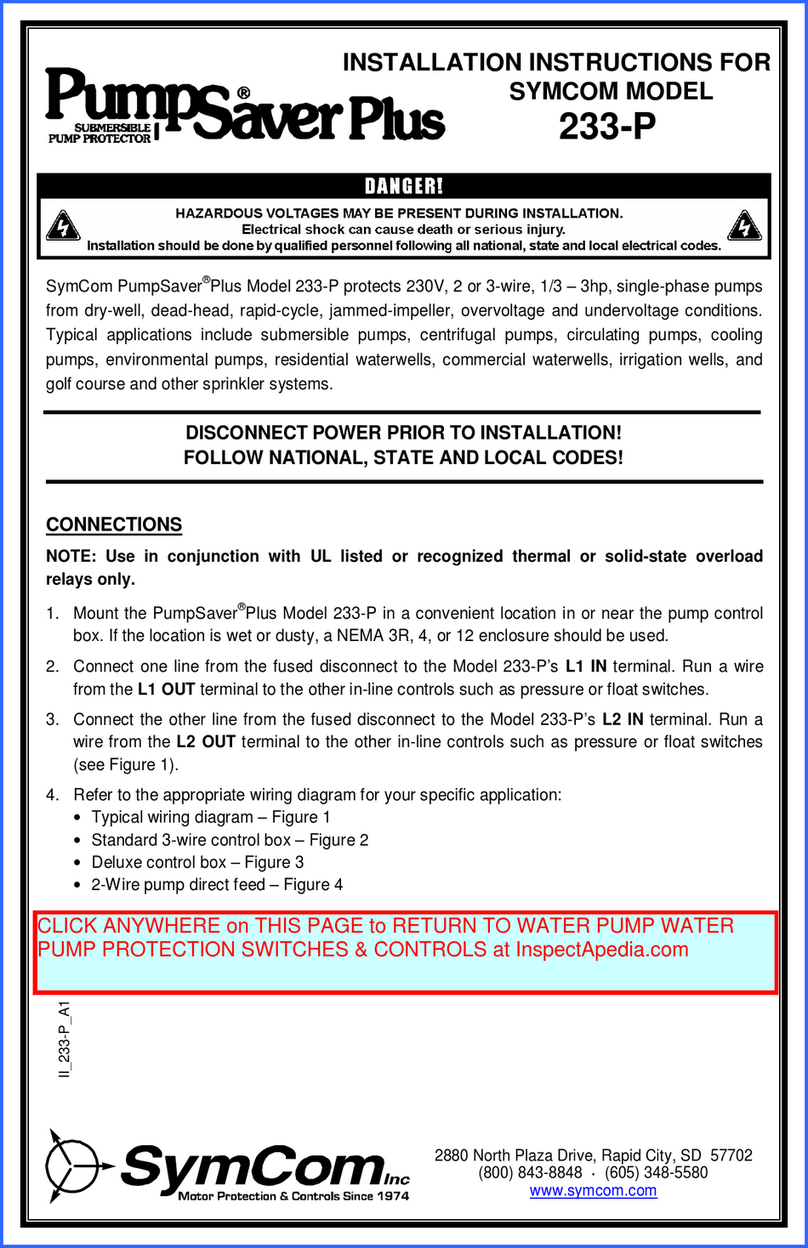
SymCom PumpSaver 235 User manual

2880 North Plaza Drive, Rapid City, SD 57702 • (800) 843-8848
INSTALLATION INSTRUCTIONS FOR
SYMCOM’S PUMPSAVER
MODEL 235
CONNECTIONS
The Model 235 Single-phase PumpSaver® is a pump monitor designed to
protect single phase pumps from dry well, dead head, rapid cycle, jammed
impeller, and over / under voltage conditions. The PumpSaver® Model 235
protects 5 to 15 HP, 230 VAC pumps. Typical applications include submersible
pumps, centrifugal pumps, circulating pumps, cooling pumps, environmental
pumps, residential water wells, commercial water wells, irrigation wells, and
golf course or other sprinkler systems.
NOTE: Use in conjunction with UL listed or recognized thermal or solid
state overload relays only.
1. Mount the PumpSaver® in a convenient location in or near the pump
control box. If the location is wet or dusty, a NEMA 3R, 4, or 12 enclosure
should be used.
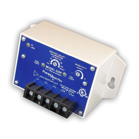
2. Connect a current transformer to the PumpSaver’s terminals marked CT1
and CT2. (see Table 1 for proper CT sizing)
3. Connect the PumpSaver’s terminals marked ‘L1’, ‘L2 IN’ and ‘L2 OUT’,
referring to Figure No. 1 for a Typical Wiring Diagram, Figure No. 2 for a
Standard Control Box Wiring Diagram, or Figure No. 3 for a Deluxe Control
Box Wiring Diagram.
Note: One line from the fused disconnect must pass through the current
transformer.
The Model 235 will not function without an external CT.
NOTE: The PumpSaver® may not detect a dead head (blocked pipe)
condition on applications where the pump is undersized for a
given motor or ow restrictors are used on high stage pumps or
low yield wells.

07/11/03 -2-
Figure No. 1: Typical Wiring Diagram
PRESSURE SWITCH
OR OTHER CONTROL
Table No. 1: CT Selection
Size Current CT
5 - 7 HP 27.5 - 42.1 50:5
10 HP 51 75:5
15 HP 75 100:5

-3- 07/11/03
Figure No. 2: Standard Control Box
Figure No. 3: Deluxe Control Box

CALIBRATION / SETTINGS
Note: The PumpSaver® should be calibrated during normal
pumping conditions.
1. Turn the RESTART DELAY / CALIBRATION adjustment fully
counter-clockwise to the “CAL.” position.
2. Apply power to the PumpSaver®. The pump motor should be
running at this point.
3. When the CAL. LIGHT turns on (approximately 5 seconds), the
PumpSaver® is being calibrated. Within 10 seconds, proceed to
step 4.
4. Set the RESTART DELAY / CALIBRATION adjustment to the
desired Restart Delay (Dry Well Recovery Time). If you leave
the RESTART DELAY / CALIBRATION adjustment in the “CAL.”
position, the unit will trip off and stay off. Turn the adjustment
out of the “CAL.” position to start the pump.
Note: If the PumpSaver® immediately trips out upon
completion of the calibration process, the current
transformer may be installed incorrectly. Switch the CT1
and CT2 connections at the unit, then repeat the
calibration process beginning with Step #1.
Manual Reset Mode: If the RESTART DELAY / CALIBRATION
adjustment is set to “RESET”, the PumpSaver® is in Manual
Reset mode. After the PumpSaver® shuts down due to a voltage
or load problem, the RESTART DELAY / CALIBRATION
adjustment must be rotated out of the “RESET” position to
restart the pump.
Note: Any restart delay can be by-passed by rotating the
RESTART DELAY / CALIBRATION adjustment to the
“RESET” position and back to the desired Restart Delay
setting.
Rapid Cycling Protection: Rapid cycling is defined as more than 4
restarts in a 60 second period. The PumpSaver® will lock-out
upon detecting a rapid cycling condition until power is removed
and re-applied to the L1 IN and L2 IN terminals. See the
Diagnostics Table for instructions to diagnose a rapid cycling
fault.
07/11/03 -4-

-5- 07/11/03
DIAGNOSTIC INDICATOR TABLE
RUN LIGHT
CAL.
LIGHT PROBLEM or FUNCTION CORRECTIVE ACTION
On Steady Off
RUN:
Pump is running, no problems in
operation.
None
On Steady On Steady
CAL:
The PumpSaver® is in the
calibration process.
None
Off On Steady
CAL COMPLETE:
The PumpSaver® is calibrated,
RESTART DELAY / CALIBRATION
pot was left in “CAL.” position.
Pump is off.
Pump will restart as soon as
the RESTART DELAY /
CALIBRATION pot is rotated
out of the “CAL.” position.
Off Off
OFF / MANUAL RESTART:
The pump is not running. Either the
PumpSaver® has tripped on dry
run, dead head, or overload while
the RESTART DELAY /
CALIBRATION pot was in the
“RESET” position or source power
is not present.
If pot is in the “RESET”
position, rotate out of that
position. If the “CAL” light
blinks, check for an
overload condition. If the
“RUN” light blinks, look for a
dry run or dead head
condition. If no lights come
on, check incoming power for
adequate voltage.
Blinking Off
DRY RUN / DEAD HEAD:
The PumpSaver® has shut the
pump off due to a dry run or dead
head condition. The unit is timing
through the restart delay and will
try to restart.
Check for restricted ow or
inadequate supply of liquid.
Off Blinking
OVERLOAD:
The PumpSaver® has shut the
pump off due to an overload
condition. The unit is timing
through the restart delay and will
try to restart if line voltage is at an
acceptable level.
Check for low or high voltage
or jammed pump impellers. If
these condition do not exist,
recalibrate the unit while it is
drawing higher amps (Amps
should not exceed SFA).
Blinking alter-
nately with the
CAL. Light
Blinking
alternately
with the
RUN Light
VOLTAGE FAULT:
The PumpSaver® is preventing the
pump from starting due to voltage
problems. The voltage is being
interrogated and the unit will
remain in this mode until the
voltage is at an acceptable level.
If the unit remains in this state
for more than 5 seconds,
check for high or low voltage.
Blinking in uni-
son with the
CAL. Light
Blinking in
unison with
the RUN
Light
RAPID CYCLE:
The PumpSaver ®has shut down
on rapid cycling. Power must be
removed and reapplied to reset
the unit.
Check for broken bladder on
the pressure tank (if used), or
check for defective pressure
or oat switch.
CONGRATULATIONS!!
YOU HAVE JUST INSTALLED THE FINEST
PUMP PROTECTION AVAILABLE!!

SPECIFICATIONS
1-Phase Line Voltage 230 VAC
Load Range 5 to 15 hp (external CT required)
Frequency 50 or 60 Hz
Note: 50 Hz will increase all delay timers by 20%
Operating Points
Overload 125% of Calibration Point
Underload (Dry Well)1Aproximately 80% of Calibration Point
Over Voltage Trip Point 265 VAC
Under Voltage Trip Point 190 VAC
Number of Restarts Allowed
in a 60 Second Period (Rapid
Cycle)
4
Trip Delay Time (Overload) 5 Seconds
Trip Delay Time (Dry Well) 2 Seconds
Restart Delay Time
Over / Under Voltage 5 Seconds
All Other Faults Manual, 2-225 Minutes
Output Contact Rating - SPST
Pilot Duty
480 VA @ 240 VAC
1 HP, 240 VAC
Electrostatic Discharge (ESD) IEC 1000-4-2, Level 2,
4 kv Contact, 6 kv Air
Power Consumption 5 Watts (maximum)
Weight
PumpSaver 14 Ounces
PumpSaver with 3R Enclosure 1.6 Pounds
Terminal
Wire AWG 12-22 Gauge
Maximum Torque 7 inch-pounds
Operating Temperature -40o to +70o C
CSA LR 46510-12
07/11/03 -6-
1High Sensitivity Mode increases Dry Well Trip to approximately 87% of
Calibrated Amperage. Call Factory at (800) 843-8848 or (605) 348-5580 for
details.

-7- 07/11/03
DIMENSIONS
4.030" (102.36)
5.250" (133.35)
4.500" (114.30)
.375"
(9.53)
2.900"
(73.66)
0.150" (3.81)
2.163"
(54.94)
2.913"
(73.99)
TERMINAL STRIP
SymCom warrants its microcontroller based products against defects in
material or workmanship for a period of ve (5) years* from the date of
manufacture. All other products manufactured by SymCom shall be
warranted against defects in material and workmanship for a period of two (2)
years from the date of manufacture. For complete information on warranty,
liability, terms, and conditions, please refer to the SymCom Terms and
Conditions of Sale document.
* The 520 Series has a one (1) year warranty and the LSRU series has a two
(2) year warranty.
Any questions or comments call SymCom at 1-800-843-8848 or
1-605-348-5580

2880 North Plaza Drive, Rapid City, SD 57702
Phone:(800) 843-8848 or (605) 348-5580
FAX: (605) 348-5685
Visit our website at
www.symcominc.com for our
complete catalog and new
product listings!
Table of contents
Other SymCom Water Pump manuals
Popular Water Pump manuals by other brands

Grundfos
Grundfos MAGNA 25-40 Installation and operating instructions

Gardena
Gardena WSP 7000 operating instructions

Stuart Turner
Stuart Turner Showermate U2.6 bar Single Installation, operation & maintenance instructions

Clarke
Clarke MSP12 manual

Gormann-Rupp Pumps
Gormann-Rupp Pumps PA Series Installation, operation, and maintenance manual with parts list

Stuart Turner
Stuart Turner CH 4-30 PS Installation, operation & maintenance instructions