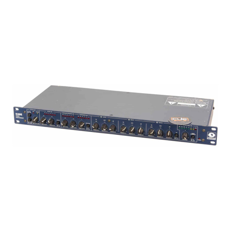
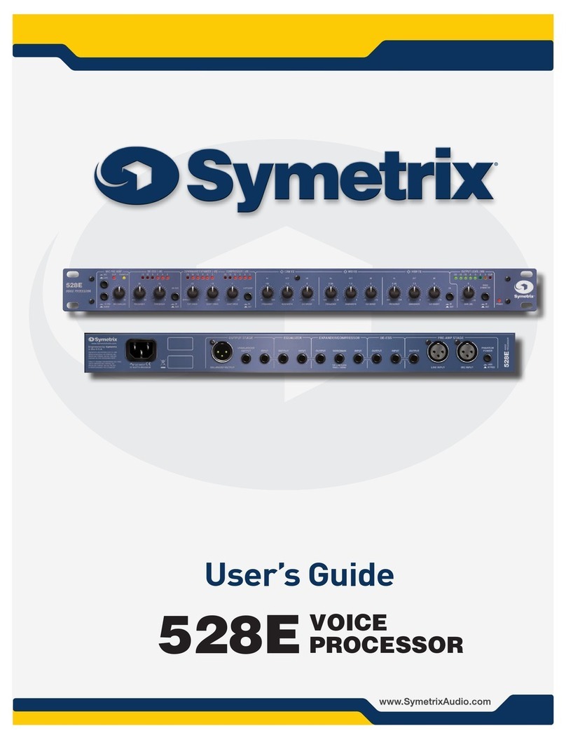
Symetrix 628 Digital Voice Processor User manual

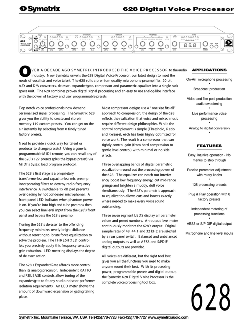
628 Digital Voice Processor
User’s Guide
628

i
Table of Contents
Chapter 1 Introduction 1
Chapter 2 Operator Safety Summary 2
Chapter 3 Product Tour and Operations Guide 3
Chapter 4 Audio Processing Basics 14
Chapter 5 Solutions to Possible Problems 20
Chapter 6 Repair and Warranty Information 23
Chapter 7 Symetrix Limited Warranty 24
Chapter 8 Specifications 25
Chapter 9 Architect’s and Engineering Specifications 26
Appendix A Symetrix 628 Factory Presets 27
Appendix B Symetrix 628 Preset Worksheet 28
Appendix C Output Level Conversion 29
Appendix D RC-1 Remote Control 31
Appendix E Input/Output Connections 34
Appendix F Declaration of Conformity 35
RevB.01,October7,1999
Symetrixpartnumber: 53628-0B01
Subject to change at our whim and fancy without notice.
©1999,Symetrix,Inc.Allrightreserved.
Symetrixis a registered trademark of Symetrix,Inc.
Mention of third-party products is for informational
purposes only and constitutes neither an endorsement
nor a recommendation. Symetrix assumes no
responsibility with regard to the performance or use
of these products.
Under copyright laws, no part of this manual may be
reproduced or transmitted in any form or by any
means, electronic or mechanical, including photo-
copying, scanning, recording or by any information
storage and retrieval system, without permission, in
writing, from Symetrix, Inc.
14926 35th Ave. West
Lynnwood, WA 98037 USA
Tel (425) 787-3222
Fax (425) 787-3211
Email: [email protected]
628

628
1
IntroductionChapter 1
Developmentofthe Symetrix 628 grew from requests
by users of our 528 and 528E Voice Processors.
Many were frustrated that their 528 required tweaks
of the processing parameters with each change in
vocalist or broadcaster. Otherwise, they were forced
to compromise their microphone processing by
adopting a “one size fits all” approach with a single
set of processing settings. Most users needed an
affordable, easy-to-use, voice processor which
allowed the creation and recall of a set of processing
parameters for individual users. We responded with
adigitalversionofthe528E-theSymetrix628Digital
VoiceProcessor.
Use your new 628 with any professional low-
impedance, balanced microphone. The 628 powers
balanced, phantom-powered microphones via an
integral phantom supply. The input circuit uses
matched resistors to attain a high common-mode
rejectionratio (CMMR),andmultistage filters
preventRFIproblems. AfrontpanelMIC/LINE
switch selects between the microphone input and
line input. The GAIN control adjusts both micro-
phone and line input signals.
The input stage feeds a 20 bit A/D converter, then a
24 bit Motorola digital signal processor takes over to
handle the signal dynamics. The 628’s De-Esser
compresses undesirable high-frequency sounds
above the user-selected threshold. The De-esser
attacks only excess sibilance sounds.
RATIOand RELEASE controls onthe 628’s discrete
EXPANDER/GATEsectionofferinfinitelymore
adjustment range than the 528 or 528E. On the
analog units, the EXPANDER is limited to a single
THRESHOLDcontrolintheCOMPRESSORstage.
The 628’s RATIO control varies function of the
stage between expansion and gating. The 628’s
RELEASE control selects the speed at which the
EXPANDER/GATEoperates.
The628’sCOMPRESSORstageoffersimprovement
overearlier modelswiththeaddition ofaRELEASE
control. WeretainedthefamiliarTHRESHOLDand
RATIO controls. Separate LED meters for both the
COMPRESSORandEXPANDER/GATEstages
provide visual indication of the amount of process-
ing taking place in each section.
The 628 bundles all three parametric equalizers into a
single control area. A push button switch toggles
between LOW, MID and HIGH frequency sections.
The equalizer bands and controls remain the same as
onthe528E,exceptyounowreadFREQUENCY,
BANDWIDTHandCUTorBOOSTonthenumeric
display.
TheOUTPUT LEVEL pot tweaks the outputgain
and the LED headroom meter provides a visual
indication of the output level. The 628 steps through
its128 presetswithatwist ofthePRESETNUMBER
control. Load the indicated preset by pushing the
LOAD button. You save changes to a preset by
pushing the SAVE button.
The 628 provides both analog and digital outputs.
The analog output can be at line level (+4 dBu) or
switched to microphone level (-40 dBu) via internal
jumpers. The digital output supports both AES/EBU
andS/PDIFformatsat sample rates of 32 kHz, 44.1
kHzand48kHz.
Sounds easy doesn’t it? We don’t make you step
through multilayer menus. The 628 purposely looks
and feels like the 528E; we traded out the analog pots
for binary switches. When you need to make a
change just grab the right knob and give it a turn!
The 628’s front panel is very intuitive; you probably
feel that you don’t need to finish reading the manual.
Don’t cheat yourself, read the manual, learn the finer
points of operating the 628, and get the maximum
benefitfrom yournew628Digital VoiceProcessor.
Call us with any questions or if you have something
tasty on the stove to share (we’ll eat anything but
anchovies).
Front panel
Rear panel
MASTER
HIGHMIDLOW
PARAMETRIC EQ
SAVELOAD
NUMBER
PRESET
HEADROOM (dB)
LEVEL
OUTPUT
(dB)(Oct) CUT/BOOST
(kHz)
FREQUENCY BANDWIDTH
4(680-20kHZ)(20-500Hz) (160-6300Hz) ACTIVE 2028 24 1216 8 CLIP
COMPRESSOREXPANDER/GATEDE-ESSER
MIC
PRE-AMP
(Sec)
RELEASE
(dBFS)
THRESHOLD (X:1)
RATIO
RELEASE
(Sec)
RATIO
(X:1)
THRESHOLD
(dBFS)
(kHz)
FREQUENCY
75
-15 PAD
NORM
15
GAIN
(dB)
628
DIGITAL VOICE
PROCESSOR
(dBFS)
THRESHOLD
-6
PHANTOM
CLIP -18 -12
-15 -9 ACTIVE-3 -12-18 -15 -6-9 -3 ACTIVE -9-15-18 -12 -3-6 ACTIVE
LINE
+20-12
POWER
PHANTOM
ON
OFF
MICROPHONEANALOG LEFT LINE
RATE
SAMPLE
32kHz
44.1kHz
48kHz
SELECT
UNBALANCED
OUTPUT
S/P DIF ANALOG RIGHT
UNBALANCED
INPUT
SELECT
S/P DIF
AES/EBU
MIDI/RC-1 IN AES/EBU
MIDI
CHANNEL
MIDI
PROGRAM
1314
12
1
16
2
73
15
11
8
9
10
DUMP SELECT
628
DIGITAL VOICE
PROCESSOR
64
5
MIDI OUT/THRU
REMOTE CONTROL
MAXIMUM
15 WATTS
AC INPUT
RÉFÉREZ TOUTE RÉPARATION À UN TECHNICIEN QUALIFIÉ.
FABRIQUÉ AUX E.-U. PAR SYMETRIX INC., LYNNWOOD, WASHINGTON.
MANUFACTURED IN LYNNWOOD, WA, USA
DIGITAL OUTPUT

628
2
The information in this summary is intended
for persons who operate the equipment as well
as repair personnel. Specific warnings and
cautions are found throughout this manual
wherever they may apply; they do not appear
in this summary.
The notational conventions used in this
manual and on the equipment itself are
described in the following paragraphs.
The lightning flash with arrowhead symbol
within an equilateral triangle is intended to alert
the user of the presence of un-insulated
"dangerous voltage" within the product's
enclosure that may be of sufficient magnitude
to constitute a risk of electric shock to persons.
The exclamation point within an equilateral
triangle is intended to alert the user of the
presence of important operating and mainte-
nance (servicing) instructions in the literature
accompanying the 628 (i.e. this manual).
Caution:To prevent electric shock, do not
use the polarized plug supplied
with the 628 with any extension
cord, receptacle, or other outlet
unless the blades can be fully
inserted.
Terms
Several notational conventions are used in this
manual. Some paragraphs may use Note,
Caution, or Warning as a heading or certain
typefaces and capitalization are used to
identify certain words. These are:
Note Identifies information that needs
extra emphasis. A Note generally
supplies extra information to
help you to better use the 628.
Equipment Markings
Operator Safety Summary Chapter 2
Caution Identifies information that, if not
heeded, may cause damage to
the 628 or other equipment in
your system.
Warning Identifies information that, if
ignored, may be hazardous to
your health or that of others.
CAPITALS Controls, switches or other
markings on the 628’s chassis.
Boldface Strong emphasis.
Power source - Electrical power require-
ments for US and Canadian models are 117
VAC Nominal, 105 to 125 VAC, 60 Hz, 20
Watts maximum. UL and C-UL listing applies
only to this rating. This product is intended to
operate from a power source that does not
apply more than 255Vrms between the power
supply conductors or between either power
supply conductor and ground. A protective
ground connection, by way of the grounding
conductor in the power cord, is essential for
safe operation.
Danger from loss of ground - If the protec-
tive ground connection is lost, all accessible
conductive parts, including knobs and controls
that may appear to be insulated, can render an
electric shock.
Proper power cord - Use only the power
supply specified for the product. Use only a
power supply that is in good condition.
Operating location - This product is intended
for use in a rack-mounted environment. Do
not operate this equipment under any of the
following conditions: explosive atmospheres,
in wet locations, in inclement weather,
improper or unknown AC mains voltage, or if
improperly fused.
Stay out of the box - To avoid personal injury
or injury to others, do not remove the product
covers or panels. Do not operate the product
without the covers and panels properly
installed.
AVIS: NE PAS OUVRIR
Il ne se trouve a l’interieur aucune piece pourvant entre reparée l’usager.
SEE OWNERS MANUAL. VOIR CAHIER D’INSTRUCTIONS.
S’adresser a un reparateur compétent.
RISQUE DE CHOC ELECTRIQUE
N
o user serviceable parts inside. Refer servicing to qualified service personnel
.
CAUTION
WARNING: TO REDUCE THE RISK OF FIRE OR
ELECTRIC SHOCK DO NOT EXPOSE
THIS EQUIPMENT TO RAIN OR MOISTURE
DO NOT OPEN
RISK OF ELECTRIC SHOCK
Warning: To prevent hazard
or damage, ensure that only
microphone cables and
microphones designed in
compliance with IEC-268-
15A are connected.

628
3
Product Tour and Operations Guide
Chapter 3
This chapter provides an overview of the connectors and controls on the 628. We’ll explain the
operation of each as we go along. Please read through this chapter completely first and then refer
to it when necessary as you make connections to the 628 and begin operating the unit.
Now that you’ve ripped open the box ...
Start by mounting the 628 in your equipment rack with #10-32 screws (not provided). Use plastic or
nylon washers (also not provided) to minimize markings to the front panel. The 628 requires no
special ventilation; just don’t mount it directly over heat generating devices (such as your 200 watt
per channel power amp or your pizza oven). We’ll start around back.
LISTED
813 COMMERCIAL
AUDIO EQUIP. 2T38
628
PROCESSOR
DIGITAL VOICE
MANUFACTURED IN LYNNWOOD, WA, USA
15 WATTS
AC INPUT
MAXIMUM
FABRIQUÉAUX E.-U. PAR SYMETRIX INC., LYNNWOOD, WASHINGTON.
RÉFÉREZ TOUTE RÉPARATION ÀUN TECHNICIEN QUALIFIÉ.
C
Plug the EIN power cord supplied with the 628 into the mains connector on the rear of the unit.
While you’re there, verify that the voltage specification on the 628 matches your local mains
voltage. Look for the voltage specification on the adhesive tag to the right of the power
connector. Check that the plug matches your mains receptacle.
Warning: If the voltagespecifieddoesnotmatch your localmainsvoltage,orif
theplugonthepowercordis not correct for your mains receptacle, STOP! Call the
Symetrixdealer(oryourcountry’sdistributor)whosuppliedyourunitandtradethe
628foraunitbuiltforyour mains voltage.
If everything looks consistent, you may plug the 628 into a mains receptacle. Please verify that
the plug fits all the way into the receptacle so that none of the blades are exposed. Once con-
nected to mains power, the 628 will power up. There is no ON/OFF power switch on the 628.
Warning: The628is intended to beelectricallygrounded. It is supplied witha
three-wiregroundingplugwhichhasa grounding pin. This plug will fit only a
groundedAC outlet. This is a safetyfeature. If you are unable toinsert the plug into
theoutlet, contact a licensedelectriciantoreplacetheoutlet with a properly
groundedoutlet. Donotdefeatthepurposeofthegrounding plugwithanadapter.
PHANTOM
INPUT
ON
OFF
MICROPHONE
POWER
LINE
Connecting with your microphone ...
Next connect your microphone cable
to the 3 pin, female XLR connector on
the far right side of the rear panel, as
viewed from the rear of the 628. The
628 wants to see an output from a
balanced, low-impedance professional
microphone. If the connector on your
microphone connector does not
matchtheMICROPHONEINPUT
connector of the 628 have a qualified
technician replace the cable connector with a 3 pin, male XLR connector.
Caution: Large transients (loud “pops” and “whoomphs”) may be induced when plugging and
unplugging the microphone connector. Transients also occur when you connect power to
the 628. If you have connected the output of the 628 to a console input or other audio

628
4
device, please turn down the fader, or input gain control, to protect your equipment from
any transients.
Note: We wired the microphone input with Pin #2 high (+), Pin #3 low (-) and Pin #1
ground or shield.
Warning: Topreventhazardordamage,ensurethatonlymicrophonecablesand
microphonesdesignedincompliancewithIEC-268-15Aareconnected.
If your microphone is a dynamic type, leave the PHANTOM POWER switch in the OFF position
(out). Switch the PHANTOM POWER to the ON position (in) when using a condenser micro-
phone. Please consult your microphone manual if you don’t know which type of you have. The
front panel PHANTOM LED will light when the phantom voltage is switched on.
Caution: Large transients (loud “pops” and “whoomphs”) will be generated when
turning the phantom power on and off. If you have connected the output of the
628 to a console input or other audio device, please turn down the fader, or
input gain control, to protect your equipment from any transients.
Connecting to a line level audio source ...
When you plan to use the 628 with a line level audio source connection may be made to either the
3 pin, female XLR connector or the 1/4 inch TRS jack. Pin #2 is high (+) on the XLR; tip is high (+)
on the TRS jack. The 628 will accept a line level signal up to +22 dBu at the LINE INPUT connec-
tors. You may connect either a balanced or unbalanced circuit to the 628’s input. It is OK to plug
a TS (tip & sleeve) plug into the TRS (tip, ring & sleeve) input jack. Use the GAIN control to
adjust the line level input signal.
Caution: The 628 accepts analog inputs only. There is no provision for a digital input
signal.
Warning: Do not connect the line input of the 628 directly to a telephone line. Use a
telephonecouplerortelephonehybrid forinterfacingwithatelephoneline.
MIC
PRE-AMP
75
-15 PAD
NORM
15
GAIN
(dB)
PHANTOM
CLIP
LINE
+20-12
Locate the MIC/LINE switch on the far left side of the 628 front panel. When using a microphone
as the audio source, make sure that the button is pushed in. If you wish to use your line level
audio source, push the MIC/LINE switch to the out position.
You can’t have it both ways ...
The 628 allows you to use either the microphone input or the line input,
but not both simultaneously. When you select the “MIC” position, the
628 disconnects the line level input. If you select the “LINE” input the
microphone preamp is disconnected from the input circuit. This keeps
residual noise to a minimum.
Too hot?
Directly below the MIC/LINE switch is the switch for a 15 dB PAD (a
fixed attenuator). You will want this switch in the NORM (normal)
position for most microphones. If you know that your condenser
microphone has an unusually high output, change the pad switch to the
15 PAD position (push-button in).
Caution: If you notice the CLIP LED flashing while you use the 628 and you have the
GAIN attenuator at a 9:00 o’clock position or lower, you should engage the 15
dB PAD. The input circuit will also clip if a line level audio source is connected
to the MICROPHONE INPUT connector.

628
5
Gain adjustment ...
The remaining task in setting up your 628 input signal is adjustment of the input GAIN attenuator.
This sets up proper gain structure through the 628’s A/D converter. First set the push buttons of
the De-esser, Expander/Gate, Compressor and Parametric EQ to the bypass position. All of the
ACTIVE LEDs will be off. Turn the OUTPUT LEVEL until “0” (unity gain) shows on the MASTER
display below the LED headroom display on the right side of the 628.
While speaking into the microphone in your best “announcer voice”, or while feeding the 628 line
level audio, adjust the input GAIN attenuator until the LED headroom display peaks at an average
of -8 dBfs. All of the green LEDs and the first yellow LED will light. It’s OK if the second yellow
LED (-4 dBfs) flashes on occasional loud peaks.
Take care not to clip the input preamplifier. Check this by using your loudest normal voice when
setting the input GAIN attenuator. We found that a knob position of 12 o'clock is about right for
dynamic microphones. Too much gain applied in the preamplifier also adds unnecessary noise in
the signal path.
Note: The 628’s GAIN control adjusts either the microphone preamplifier gain or the
line input level depending on which input is selected.
Where’s the VU meter?
What’s this “headroom meter” stuff? The analog 528 and 528E use an LED VU meter. There is no
"0" on the 628's meter. When 528s and 528Es hit “0 dB” on the analog meter, the output is 0 dBm
(+4 dBu). The output of these analog processors is referenced to 600 milliwatts into a 600 ohm
load.
Digital audio equipment references signal levels to the clip point. With digital equipment, there is
no “0 dBm” reference point. A signal passing through the 628 at a level of -4 dBfs (dB full scale) is
4 dB below clipping, NOT at -4dBu. The 628 clips at +22 dBu. This means that the -4 dBfs signal
equates to +18 dBu (4 dB below +22 dBu).
The THRESHOLD controls and metering in the Compressor, Downward Expander and De-esser
sections of the 628 are also referenced to the clip point (0 dBfs). When a threshold is set for -10.0
dB, it is set at 10 dBu below clipping, or at a value of +12 dBu.
Let’s compare the difference between a VU meter and a headroom meter with the speedometer in
your car. Your speedometer is like a VU meter. When you travel at 55 m.p.h. (the legal speed limit,
in this example), the speedometer reads “55.” 55 m.p.h. is an absolute speed just as 0 dBm is an
absolute voltage. If you travel at 45 m.p.h., your analog speedometer would read 45 m.p.h..
A “headroom” speedometer would express the speed limit (55 m.p.h.) as “0 m.p.h..” If you travel at
45 m.p.h., the headroom speedometer would display “-10 m.p.h..” The “headroom” speedometer
tells you that you are traveling at a speed 10 m.p.h. below the legal limit. You could speed up
another 10 m.p.h. before getting “clipped” by the cops.
You always want to drive close to the speed limit on the freeway, and the input of digital audio
equipment should be operated as close to the clip point of the A/D converter as possible. This
assures the best resolution of the digital signal. A signal passing through the 628 which registers
-4 dBfs on the headroom meter produces 20-bit audio. A signal passing through with peaks of only
-20 dBfs renders only 14-bit audio. Best digital resolution and optimum signal-to-noise perfor-
mance dictates that you keep audio passing through the 628 as high as possible on the headroom
meter.
Let’s move around back again and connect the 628 output.

628
6
If you plan to use the balanced, line level (+4 dBu) output, the job is easy. Plug a properly wired 3
pin, female XLR connector into one of the analog output connectors. Pin #2 is high (+), pin #3 is
low (-) and pin #1 is circuit ground.
You will notice that we provided
two outputs, ANALOG LEFT and
ANALOGRIGHT. You may use
either, or both.
When you need an analog
unbalanced line level output,
please use one, or both, of the 1/4
inch TS (Tip/Sleeve) jacks. The tip
is high (+); sleeve is ground (-).
The analog output of the 628 may seem higher than the output of your 528 or 528E. You’re right!
Because we want to operate digital circuits closer to the clip point, the analog output signal will
also operate closer to its clip point. If this presents a problem by overloading your console input,
turn down the input trimmer for that channel. If your console does not provide an input trimmer,
insert a fixed pad between the analog output of the 628 and your console input. You may also load
the output of the 628 with a 620 ohm resistor when connecting it to a balanced, bridging input.
Connect the resistor across the high (+) and low (-) connections at the console input.
Note: You may be tempted to simply turn down the OUTPUT LEVEL control on the
628. This is a digital gain control. Remember that digital devices perform
better when operated close to their clip point.
But, I need a mic level output ...
We recommend that you use a line level analog output whenever possible. But, in the real world,
things aren’t always this neat. Some consoles only allow microphone level (-50 dBu) inputs for the
channels providing microphone functions (such as speaker muting or on-air light switching).
Please call your console manufacturer and complain loudly about their lack of flexibility. Any
“quality” console input should provide switching between microphone and line level.
Don’t expect much help from the console guys. That’s OK; we built a solution into the 628. When
backed against the wall, you may convert one, or both, XLR analog outputs of the 628 to micro-
phone level output.
Warning: Thischange isaccomplishedinsidethe boxviajumpersandmust bemadebya
qualifiedelectronictechnician. A technician can find instructionsforthisprocedure
inAppendix C of thismanual. Youmayreturnyour628 to us forconversionifyoudo
nothave aqualifiedtechnicianavailable. Please callourCustomerService Depart-
mentforareturnauthorizationnumber.
SAMPLE
OUTP
U
SELECT
48kHz
S/P DIF
AES/EBU
44.1kHz
32kHz
S/P DIF
RATE
AES/EBU
SELECT
DIGITAL OUTPUT
And, I want the digital output ...
Making use of the 628’s digital output requires a few more steps. First determine the sample rate
which you need to feed to your digital input. Move the SAMPLE RATE SELECT toggle switch to
the proper sample rate setting. You must use
sampleratesof 48 kHz, 44.1 kHz or 32kHz.
The 628 makes no provision for synchroniza-
tion to an external clock.
TheDIGITALOUTPUT SELECTswitch
activates one of the two digital outputs. The
AES/EBU output appears on the 3 pin, male
XLR connector. The Sony/Phillips Digital
Interface (S/P DIF) output is on the RCA pin
Under normal circumstances ...
T
PUTS
UNBALANCED
ANALOG RIGHT
UNBALANCED
ANALOG LEFT

628
7
L
ISTED
O
MMERCIAL
EQUIP. 2T38
POWER IN FROM
SYMETRIX 628
MIDI OUT
O
LARITY
T
S D.C.
RING -
CHANNEL 1
SELECT
REMOTE CONTROL
MIDIMIDI
8
PROCESSOR
DIGITAL VOICE
MIDI OUT/THRU MIDI/RC-1 IN
SELECT
14
13
12
DUMP
16
1
10
9
543
76
82
15
11
O
OD, WA, USA
CHANNELPROGRAM
Remote control & MIDI ...
If you are not using the Symetrix RC-1 remote control, you can sit out this section. If you have the
RC-1, plug one end of the 7 pin
DIN cable (supplied with the
RC-1)into theMIDI/RC-1IN
connector. Plug the other end
of the cable into the RC-1
Remote Control. Make sure that
theMIDICHANNELSELECT
rotary switch identifies the 628
as Channel #1. Read the
channel number on the switch
or on the MASTER display as
you turn the MIDI CHANNEL
SELECTswitch.
Note: Youwill find
furtherinforma-
tion on the RC-1,
including instruction
on how to change the
RC-1’sMIDI channel
identification,in
Appendix D at the rear
of this manual.
With the Symetrix RC-1 connected to the 628 you can select and load any of the first eleven presets
stored in your 628 by pushing the corresponding button on the RC-1. The BYPASS button loads
program #0 which remains a dedicated bypass function and may not be programmed.
When you first connect the RC-1, none of the LEDs will light. Push the button for preset #1. The
LED next to the Program 1 button will light. The MASTER display on the 628's front panel should
display "1", indicating that the command from he RC-1 was received and preset #1 was loaded.
The LEDs on the RC-1 do not provided positive confirmation of which preset is selected on the
628. They simply serve as reminders of which program selection was last sent to the 628. If a
program selection change is made at the front panel PRESET NUMBER knob, the LEDs on the RC-1
will not reflect the change. When in doubt, check the 628's MASTER display, or push the desired
preset button on the RC-1 even though it may already be lighted.
The Symetrix RC-1 cannot make changes to any individual operating parameter on the 628. It
selects and loads presets #0 through #11 only. There is no button lockout or other security feature
provided on the RC-1. If you accidentally hit one of the buttons, you will accidentally change the
processing preset on the 628.
Caution: The Symetrix RC-1 includes a jack for an optional 9 VDC power supply (not sup
plied). If you use the RC-1 with the 628, the RC-1 takes its power from the 628. No
external power supply is required when using the RC-1 with the 628. The optional
9VDC connection allows you to use the RC-1 with MIDI controlled devices (like the
Symetrix 601 and 602).
connector. The 628 provides signal to only one digital output format at a time.
As you switch between AES/EBU and S/P DIF, the MASTER display on the front panel will reflect
the change. When you select AES/EBU the display will read "PrO", indicating "professional". If
you use the S/P DIF format, the MASTER display will read "COn", reflecting the "consumer"
format.

628
8
MASTER
SAVELOAD
NUMBER
PRESET
HEADROOM (dB)
LEVEL
OUTPUT
42028 24 1216 8 CLIP
Preset selection ...
Selecting a processing preset on the 628 is very simple. The MASTER numeric display normally
shows the preset currently in use. To change to a different preset, turn the PRESET NUMBER
knob until the
desired preset
number appears
in the window.
The preset
numberwill
flash indicating
that it has been
selected but not
yet loaded.
Push the LOAD
button to the
right of the PRESET NUMBER knob. Now the window will display the preset number without
flashing, indicating that the 628 has loaded the new preset.
When you unpack your 628, you will find programs 1 through 119 blank. We shipped your 628
with the parameters at these presets set for unity gain with no processing. You will find the pre-
programmed factory presets at positions 120 through 127. We programmed these as “read only”
programs; they cannot be changed. You may move them to more convenient locations and then
make any required changes. Here’s how:
Moving a preset program ...
Should you need to copy an existing preset program to a different preset number, you will need to
learn about the SAVE button. This function instructs the 628 to save changes to the selected
preset. First, select and load the program which you want to copy. Second, turn the PRESET
NUMBER knob until the MASTER display shows the location where you wish to copy the loaded
program; the display will flash the number. Third, push the SAVE button; the MASTER display
will show the flashing letters "Sto" (Store). Push the SAVE button again and the 628 will copy the
selected preset program to the new location.
Until you press the SAVE button the second time the preset program will not be copied tot he new
location. This gives you a second chance in the event that the SAVE button is accidently pushed
in the heat of processing. The first push of the SAVE button arms the 628 to make a change and
displays "Sto" in the MASTER display window. The second push permanently records the
change.
Note: Do not try to use the RC-1 Remote Control to select the target location where you want to
copy the preset program. Pushing a button on the RC-1 accomplishes TWO functions.
Those of you using other MIDI control devices with the 628 will know what to do with the MIDI IN
jack,theMIDI OUT/THRU jack and the MIDI CHANNEL SELECT switch. You’ll find instruction
in the manual which came with your MIDI controller.
Copying programs between units with MIDI ...
Here’s a neat MIDI trick for users of multiple 628s who want all of their units programmed alike.
You can set all programs and parameters manually or you can use MIDI to copy all programs from
one 628 to another. You will need a standard MIDI cable, or 5 pin DIN cable, connected between
the MIDI OUT/THRU connector of your programmed unit (master) and the MIDI/IN connector of
the unit which you want to program (slave). Both units must be on and the MIDI CHANNEL
SELECT switches must be in the Channel #1 position. Push the MIDI PROGRAM DUMP button
on the programmed unit (master). All programs will be downloaded to the slave unit. You can now
disconnect the MIDI cable from the two 628s.

628
9
The Equalizer ...
Since no one remains content to use a standard “factory preset”, you need to know how to modify
presets and create your own programs from scratch. We’ll start with the parametric equalizer
section, since EQ is the first thing
which you will want to tweak for
each individual voice.
The 628 provides three overlapping
bands of parametric equalization with
adjustable frequency and bandwidth.
Operating a parametric equalizer is
like opening a safe; you must dial in
the correct three numbers to properly
accomplish the job.
First, make sure that the equalizer is active. Momentarily push the Operate/Bypass button, and the
ACTIVE LED in the PARAMETRIC EQ section will come on. Next, use the Band Select push-
button (left of the FREQUENCY knob) to toggle between LOW, MID and HIGH until the band
which you want to adjust is selected.
The first parameter to adjust is the frequency. This selects the center frequency of equalization cut
or boost. Turn the FREQUENCY knob slowly until you feel one click. Notice that the MASTER
numeric display changes to show the frequency (in kHz) currently selected. You will change the
frequency as you continue to turn the FREQUENCY knob, and the display will flash, indicating that
you are changing an existing program.
Notice that you will not be able to dial in a frequency outside the equalizer band which you have
selected. The bands do overlap, so you can accomplish rather complex equalization tasks.
Note: If you select the 32 kHz sample rate, the high frequency band tops out at 16 kHz (680 Hz
- 16.0 kHz). The high frequency band ranges between 680 Hz and 20.0 kHz, as indicated
on the front panel, when you use either the 44.1 kHz or the 48 kHz sample rates.
When the center frequency which you want to cut or boost displays in the window, stop turning
the FREQUENCY knob. The display will flash, indicating that you have made a change in fre-
quency. Listen for the equalization change which you have made to the program. If you wish to
accept this change to the preset, push the SAVE button. The MASTER display will show the
flashing letters "Sto" (Store). Push the SAVE button again and the 628 will record the change to
the preset program. This edits the program and permanently records the change. The display will
stop flashing and display the new frequency after you save the change.
Adjustments to the equalization bandwidth (Q) are just as easy. Start by giving the BANDWIDTH
This operation SELECTS and LOADS the preset. When you copy a preset to another
location, you want to SELECT the target location then SAVE the preset which you wish to
copy at the new location.
You will find the 628's "bypass" preset at program "0". The MASTER display will show the letters
"byP" when you dial it in. You may also load the bypass program from the RC-1 Remote Control.
The bypass button is in the lower right corner (Program 0).
The bypass preset comes in handy when you need to erase a program preset from the 628. Let's
say that you want to delete preset #5. First select and load the bypass preset. Next, rotate the
PROGRAM SELECT knob until the MASTER display reads "5". Push the SAVE button. The
MASTER display will read "Sto". Push the SAVE button again. You have now copied the bypass
settings (no processing and flat EQ) into the processing preset #5. You may now start fresh with a
clean slate and build a new processing preset from scratch at preset #5.
Note: You can find a description of the factory presets and their program numbers in Appendix A.
HIGHMIDLOW
PARAMETRIC EQ
(dB)(Oct) CUT/BOOST
(kHz)
FREQUENCY BANDWIDTH
(680-20kHZ)(20-500Hz) (160-6300Hz) ACTIVE

628
10
knob a slow turn until you feel a single click. The MASTER numeric display will show the current
bandwidth setting in the program for the frequency selected. Continued rotation of the knob will
change the bandwidth and the display will show the value in octaves.
Note: The 628’s bandwidth control has a logarithmic taper. You will notice a greater
change in value with each click as the ratio increases.
Bandwidth defines the width of the cut or boost centered at the equalization frequency. When
applying a boost, the bandwidth (in octaves) is measured between the points on the curve where
the signal drops 3 dB below the boost applied at the center frequency. When a cut is applied to a
signal, the bandwidth (in octaves) is measured between the points on the curve where the signal
drops 3 dB from “flat” response.
When you need to notch out an offending hum or buzz, use a narrow bandwidth setting of .3
octaves (0.30 oct.), to suppress only the offending frequency. To boost a wide range of frequen-
cies use a broad bandwidth setting of 3 octaves (3.00 oct.), for a smoother response. Push the
SAVE button and the MASTER display will show the flashing letters “Sto”(Store). Push the SAVE
button again and the 628 will record your new bandwidth setting. This edits the program and
permanently records the change.
The amount of cut, or boost, determines the amount of change made at the equalizer center
frequency. Turn the CUT/BOOST knob slowly until one click is felt. The MASTER numeric
display will show the cut, or boost, (in decibels, dB) currently used in the processing preset.
Turning the knob further will change the cut, or boost, and the new value will show in the LCD
display. Push the SAVE button once and the MASTER display will show the flashing letters “Sto”
(Store). Push the SAVE button again and the 628 will change the program and record the new
amount of cut or boost.
An example ...
Let’s run through an example of making an equalization change to make sure that everyone is with
the program. We will add a 4 dB boost at 125 Hz with a bandwidth of 3 octaves on program #10.
1.) Start by rotating the PRESET NUMBER knob until the MASTER display reads “10.”
2.) Momentarily push the LOAD button.
3.) Now select the LOW equalization band by repeatedly pushing the Band Select
button to the left of the FREQUENCY knob until the LOW LED lights.
4.) Turn the FREQUENCY knob until the MASTER numeric display shows a
frequencyof 125Hz(.125kHz).
5.) Next, turn the BANDWIDTH knob until the MASTER numeric display indicates
3 octaves (3.00 oct.).
6.) Rotate the CUT/BOOST control until a 4 dB boost is indicated (+4.0 dB).
7.) Finally, push the SAVE button. Note that the MASTER display shows the “Sto”
message. Push the SAVE button a second time.
That’s it! You’ve changed the equalization and modified program #10.
Note: You can find more advice on equalizer theory and adjustments in Chapter 4.
The Compressor ...
Now we’ve graduated from equalization school and it’s time to move on to compressor college.
The COMPRESSOR section of the 628 operates the same way as the equalizer. When you move
any of the knobs one click, the MASTER display identifies the current value. Moving the knob
further than one click changes the value of the function. Make sure that the COMPRESSOR
section is active by momentarily pushing the Operate/Bypass button to the right of the RELEASE
control until the ACTIVE LED comes on.

628
11
COMPRESSOR
(Sec)
RELEASE
(dBFS)
THRESHOLD (X:1)
RATIO
-9-15-18 -12 -3-6 ACTIVE
TheTHRESHOLD knob sets theCOMPRES-
SOR threshold level. Audio signals arriving
at the COMPRESSOR stage above the set
value(in dBu) willtriggertheCOMPRESSOR
into action. Signals arriving at the COM-
PRESSOR below the threshold level will pass
through unaltered.
To change the threshold level, gently turn the
THRESHOLD knob until you feel one click.
The MASTER numeric display will show the
present threshold level in dBfs (decibels full-
scale). For example: if the THRESHOLD control is adjusted so that the MASTER display shows
a value of “-30” the threshold is now set at a value 30 dB below clipping. Since the 628 clips at
+22 dBu, the threshold is set at -8 dBu (+22 dBu minus 30 dB).
To change the threshold value, turn the knob until the new threshold level which you want is
displayed. To save the change, momentarily press the SAVE button in the MASTER section. The
MASTER display will show the flashing letters “Sto” (Store). Push the SAVE button again and the
628 will record the change to the threshold. This edits the program and permanently records the
change. The new threshold value has now been loaded into the program. The LED meter in the
COMPRESSOR section will now display the amount of compression applied when a signal is
present.
Use the RATIO control to vary the compression ratio of the COMPRESSOR. Use low ratios (for
example: 2:1) for gentle level control. Save the higher ratios (for example: 5:1) for more aggressive
processing (rock & roll DJ use). Change the ratio by turning the RATIO knob until a single click is
felt. The numeric display in the MASTER section will show the current ratio expressed in a value
to 1 (for example: XX:1). To change the ratio, rotate the RATIO knob until the desired ratio appears
in the MASTER numeric display. Save the change by pressing the SAVE button. The MASTER
display will show the flashing letters "Sto" (Store). Push the SAVE button again and the 628 will
record the change to the preset program. This edits the program and permanently records the
change. You will note the result of the change in compression on the LED meter in the COMPRES-
SOR section.
The RELEASE control allows you to change the release time of the COMPRESSOR. Long release
times (for example: 2.0 Sec.) produce gentle, transparent processing. Fast release times (for
example: .5 Sec.) result in aggressive, hard compression which some may find irritating. Most
operators compromise and select a release time somewhere in the middle range. Find what release
time the current preset uses by turning the RELEASE knob until one click is felt. The value in
seconds will display in the MASTER numeric display window. If you need to change the release
time, turn the RELEASE knob until the desired time is shown on the numeric display. Pushing the
SAVE button causes The MASTER display will show the flashing letters “Sto” (Store). Push the
SAVE button again and the 628 will record the change to the release time. This edits the program
and permanently records the change. You will note a change in the amount of compression on the
LED meter in the compressor section of your 628.
We have one more knob to turn before we weigh anchor on the compressor. The 628’s compressor
lowers the output level in direct proportion to the amount of compression which you dial in. When
you see the 628 compressing your voice by 6 dB, you will notice that the output level drops by
about 6 dB.
Here's where we use the OUTPUT LEVEL control to compensate for the signal lost in compression.
Grab the OUTPUT LEVEL knob and turn it until the number “6” appears in the MASTER display.
This adds 6 dB of gain to the output of your 628. Check for clipping on the MASTER output
meter. If everything looks OK, push the SAVE button twice to save this change to your compres-
sor program.

628
12
The Expander/Gate ...
Symetrix 528s and 528Es provided only a
THRESHOLDcontrol for theirdownward
expander function. In response to our user’s
requests we enlarged the expander, creating a
separateEXPANDER/GATE section with
RATIOandRELEASE time controls. The
628’s RATIO control allows this new section
to perform either as a downward expander,
gently lowering the signal level when it falls
below the threshold value, or as a gate, and
essentially turning off a signal which falls
below the threshold. Use the EXPANDER/
GATE for single-ended noise reduction to turn down any studio background noise when no one is
speaking into the microphone.
By now you can probably figure out how to make adjustments to the EXPANDER/GATE controls.
They function just like the controls on the COMPRESSOR stage. Toggle the Operate/Bypass
button to the right of the RELEASE knob to activate the EXPANDER/GATE stage. Next, turn the
THRESHOLD control gently until one click is felt. The MASTER numeric display will show you
the current threshold level below clipping (dBfs). Turn the THRESHOLD knob further to raise or
lower the threshold. Press the SAVE button and the MASTER display will show the flashing
letters “Sto” (Store). Push the SAVE button again and the 628 will record the threshold change.
In the same manner, the RATIO knob activates the display and changes the ratio of the EX-
PANDER/GATE stage. Selecting a low ratio (for example: 2:1) will cause the stage to behave like a
downward expander. When the input signal falls below the threshold, the 628 will lower the signal
at the ratio which you have chosen. In the example of a 2:1 ratio, a 1 dBu drop in the input signal
will result in a 2 dBu drop in the output signal level. The EXPANDER/GATE LED meter will reflect
the amount of downward expansion applied to the input signal.
If a higher ratio (10:1) is used, a 1 dBu drop in the input signal will result in a 10 dBu drop at the
628’s output. This resembles the function of a gate which turns off the signal when it falls below
the threshold level. Turn the RATIO knob until one click is felt and the MASTER numeric display
will show you the current program ratio (XX:1). Change the ratio by turning the knob further, and
save the change by pushing the SAVE button. The MASTER display will show the flashing letters
"Sto" (Store). Push the SAVE button again to record the change to the ratio.
The RELEASE time control tells the 628 how quickly to lower the signal level when the input audio
level falls below the defined threshold level. A short release time (for example: .500 Sec.) combined
with a high ratio (for example: 10:1) provides rapid, aggressive gating action. A sports announcer
would use this combination to minimize loud background noise when broadcasting a basketball
game. A long release time (for example: 2.50 Sec.) and a low ratio (for example: 2:1) provides gentle,
transparent downward expansion. This combination would work well in a studio to minimize air
conditioning noise or the sound of computer fans.
Slowly turn the RELEASE knob until a single click is felt. The MASTER display will show the
current release time. Change this value by continuing to turn the knob, watching the release time
value change on the display. Don’t forget to save the change by pushing the SAVE button. The
MASTER display will show the flashing letters “Sto” (Store). Push the SAVE button again to
record the release time change.
EXPANDER/GATE
RELEASE
(Sec)
RATIO
(X:1)
THRESHOLD
(dBFS)
-12-18 -15 -6-9 -3 ACTIVE
Note: Please reserve the use of the OUTPUT LEVEL to make up gain lost to the compressor. Do
not use the OUTPUT LEVEL control as an output attenuator. When you use the control
as an attenuator, you alter the gain structure of the 628 in the DSP and raise the overall
noise floor of the unit.
Note: You will find more advice on using an audio compressor in Chapter 4.

628
13
-3 ACTIVE-9-15 -12
-18
FREQUENCY
(kHz)
DE-ESSER
THRESHOLD
-6
(dBu)
The De-Esser ...
A de-esser functions as a frequency selective compressor. It lowers (compresses) the energy around a
chosenfrequency. TheTHRESHOLDoftheDE-ESSER
determines the level at which compression begins. De-essing
action begins if the input signal contains enough energy at the
specified frequency to rise above the threshold.
Push the Operate/Bypass button to turn on the DE-ESSER
sectionandlighttheACTIVELED. TurntheFREQUENCY
knob until a single click is felt. This will cause the MASTER
numeric display to show the current DE-ESSER frequency
setting (for example: 6.0 kHz.) Turning the FREQUENCY
knob further will change the frequency. Push the SAVE button
twice to record the change to the preset program.
A slow turn of the THRESHOLD knob, until one click is felt, will instruct the 628 to display the
threshold value on the MASTER numeric display. Turning the knob further will change the
threshold value. Pushing the SAVE button twice to record the change to the threshold value.
Note: You will find more information on de-essers in Chapter 4.
That’s it ...
You now can teach everyone else in the station how to use the 628, unless you don’t want to.
There are some things which are best kept secret. If you don’t want your air-talent to tweak the
parameters of their processing presets you can disable the 628’s front panel controls. After you
lock out the front panel controls, the announcers can switch between presets, but when they turn
other knobs the 628 ignores them.
Front Panel Security
Here’s how to lookout the 628’s front panel. With your index finger smartly extended, push the EQ
BAND SELECT button on the front panel and hold it in. Turn the PRESET NUMBER knob until the
MASTER display reads "LO" (Lock Out). Release the BAND SELECT button. You have now
disabled all digital front panel functions except for PRESET NUMBER selection. Anyone attempt-
ing to change the operating values can twist knobs all day long, but the 628 will ignore their
attempts.
When you need to reactivate the front panel controls, hold the EQ BAND SELECT button in and
rotate the PRESET NUMBER knob until the MASTER display reads "uLO" (unLOck). The 628's
controls will now function.
Note: Since the microphone preamp and line input GAIN control and switches are analog
functions, you cannot lockout these controls. We provide security only for the digital
control functions of the 628.
Other remaining mysteries ...
If you remain puzzled by anything happening with your new 628, check Chapter Four, Audio
Processing Basics. This presents an overview of audio processing theory and may fill in the
missing bit of information which prevents you from fully understanding your 628. Chapter Five,
Troubleshooting, covers possible problems your unit might experience due to improper connec-
tions, etc. Call us if there is anything which you just can’t figure out.

628
14
Audio Processing Basics Chapter 4
The Symetrix 628 combines digital audio processing algorithms with a three-band digital parametric
equalizer. This chapter offers a tutorial on the basics of dynamic range processing (compression)
and equalization. This combination of processing serves as the mainstay of the vocal signal
processing chain used in recording studios. The tutorial information is intended to provide a
background for the operation instruction found in this manual.
Dynamic Range Processing
Dynamic range processors fit wide-range signals into narrow-range transmission or storage
channels. The dynamic range of acoustical signals found in real life far exceeds our capacity to
store or transmit them. Confronted with this dilemma, audio engineers usually reach for a compres-
sor/limiter or downward expander as the means to fit two-pound signals into one-pound bags.
Compressor/limiters respond quickly to transients, and gently to normal speech level changes,
which keeps overall levels in check. The downward expander’s operation is the inverse of the
compressor/limiter. The expander can prevent “pumping” and “breathing”, even during high ratio
compression. Because the compressor/limiter and the downward expander interact, avoid “cross-
ing” their thresholds by setting the downward expander’s threshold higher than that of the compressor.
Strictly speaking, the terms compressor and limiter refer to different devices. Often, manufacturers
combine both into a single device called a compressor/limiter. Functionally, a compressor/limiter
lets the user define the maximum level of an audio signal. Compressor/limiters perform as either a
compressoror a limiter,butnotbothat once.
Expanders and gates perform the opposite function of compressors and limiters. Compressors
continuously reduce (compress) the dynamic range of signals above a set threshold, while expand-
ers continuously increase (expand) the dynamic range of signals below a threshold. Limiters can
be thought of as very high ratio compressors, and gates can be thought of as very high ratio expanders.
In addition to their roles as remedial signal processors, compressors serve a creative role. You can
use a compressor to improve the consistency of the voice by removing or reducing level changes
and adding power or “punch.” Generally speaking, the fluctuations of some voices may be extreme,
so experimentation is the name of the game. One combination of operating parameters will not
suffice for all voices.
Defining Dynamic Range
To begin a discussion of dynamic range processors it’s necessary to have a working definition of
dynamic range. The term is really self-descriptive, but has two distinct uses: To describe the actual
range of signal fluctuations that can pass through a piece of equipment. To define the maximum
allowable natural range of signal fluctuations. The unit of measure for audio signals is the decibel (dB).
Dynamic Range as a Specification
The maximum usable range of operation for a particular piece of gear is the difference in dB
between the noise floor and the maximum output level before clipping. In this context, dynamic
range becomes an equipment specification.
The noise floor definition is the lower limit of a circuit’s operating level, a function of its self-
generated electrical noise. Very noisy circuits have a high noise floor, quiet circuits have a low
noise floor. All circuits, even very quiet ones, have measurable noise.
The maximum output level of a circuit becomes the upper limit of usable operation. Clipping of the
audio waveform begins at this point because the signal level exceeds the capacity of the power
supply. To put levels in perspective they must be referenced to some nominal operating level, like
0 dBm (1 milliwatt across 600 ohms). That’s why noise specifications are stated as negative
numbers. Since maximum output level is usually greater than 0 dBm (+4 dBu), it’s stated as a
positive value (above 0 dBm). The difference between the noise floor and the onset of clipping
defines the dynamic range.

628
15
Dynamic Range of Sound
The other definition of dynamic range describes the natural range over which signals fluctuate.
The signals under discussion are electrical representations of sounds, so it follows that sound has
dynamic range. The dynamic range of the human voice, from a whisper to a shout, is over 100 dB.
An accurate microphone converts the sound pressure of a voice going from a whisper to a shout
into an electrical voltage having the same dynamic range.
Why Audio Compressors are Our Friends
To keep audio signals below distortion and above the noise floor, their natural dynamic range must
remain within the specified dynamic range of the circuits through which they pass. Unfortunately,
the actual dynamic range of real world signals exceeds the available dynamic range of even the best
audio processing equipment.
For example, the dynamic range of the best analog tape recorders calculates to around 80 dB, while
digital recorders top out around 96 dB. As good as these machines are, there’s still not quite
enough room for the very wide dynamic range of unprocessed audio. In order keep signals 60 dB
above the noise floor, the dynamic range of audio recorded on the analog tape recorder would have
to be restricted to 20 dB of dynamic range (80 dB minus 60 dB equals 20 dB). Signals recorded on
the digital recorder would have to be restricted to 36 dB of dynamic range (96 dB minus 60 dB
equals 36 dB).
A compressor or limiter reduces the dynamic range by setting an upper limit on the larger signals.
In some cases, it’s better to put processing to work on the lower end of the dynamic range rather
than on the upper end. In other words, instead of reducing the amount of change at the upper end
of the dynamic range with a compressor or limiter, we could increase the amount of change at the
lower end of the dynamic range with a downward expander or gate. In practice we throw away
some of the low level audio down near the noise floor.
Compressors are to Limiters as Downward Expanders are to Gates
Compressors reduce the dynamic range of their output whenever the input signal rises above the
set threshold, while downward expanders increase the dynamic range of their output whenever the
input signal falls below a set threshold.
Compressors, limiters, expanders and gates increase or decrease signal levels by some ratio. Good
compressors have an adjustable ratio, a ratio of the input level to the output level which is user-
adjustable. A compressor operating with a 2:1 ratio allows only a 1 dB increase in output level for
every 2 dB increase in input level.
Limiters operate at high ratios (greater than 10:1). At 10:1, the limiter allows only a one dB increase
in the output level for every 10 dB increase in the input level. Limiters can be thought of as high-
ratio, high-threshold compressors. They “stay out of the way” until the level goes above the
threshold. Above threshold their action becomes pronounced.
The Threshold Concept
A dynamic range processor’s activity begins once the input signal rises to, or falls below, a
predetermined level. In operation, the dynamic range processor’s sensing circuitry constantly
“looks at” the incoming signal and compares it to a reference level, the threshold level. The
operator sets that reference level via the threshold control. Remember, compressors and limiters
respond when signals at the input rise above threshold, while downward expanders and gates
respond only when signals at the input fall below the defined threshold.
Attack and Release Timing
If a compressor responded instantly to each waveform which crossed the threshold we would have
one very busy device. A signal passing through it would become a roar of constant level audio

628
16
quickly tiring anyone listening for an extended period. The compressor would purge all dynamic
range; only the frequency would vary. Heavy compression with short attack and release timing
made AM radio loud in the ‘60s, but it drove listeners to FM radio and cassette tape. “Listener
fatigue” on the AM band killed their audience by robbing their program material of all dynamic
range. Compression becomes an asset when we moderate the rate of correction.
The attack time control tells the compressor how quickly to apply compression after signals rise
above the threshold. You may compare this to how hard you step on the gas pedal in your car
when you want to accelerate. You can take nine seconds to get to 55 mph, or you can step on the
accelerator gently and take several minutes to reach 55 mph.
We state attack time as a function of decibels (of compression) per millisecond; it is a rate of
attack. This describes how much compression is applied per millisecond once the signal crosses
the compressor threshold. Using an attack time of 1.0 dB/mSec results in the application of
compression at a rate of 1 dB every millisecond until the compressor satisfies its ratio and thresh-
old requirements.
Audio containing a wide dynamic range and irregular wave forms (speech and hard rock music)
require short attack timing for tight control. Music sounds more pleasant as longer attack times
allow occasional short duration peaks to pass through without compression. Broadcast final
limiters function with very short attack timing to eliminate modulation overshoots. Audio clipper
circuits produce absolute overshoot protection (a brick wall) with instantaneous attack times.
Release timing tells the compressor how slowly to release compression after responding to a falling
signal peak. It is a rate of release. You may compare this to how firmly you step on your car’s
brake pedal when you want to slow down. How quickly do you want to stop?
Release timing is best expressed as decibels (of compression) per second. A release time of 10 dB/
Sec allows the compressor to release compression at a rate of 10 decibels every second. The faster
the release time, the more aggressive the compressor operation.
Speech, with its irregular wave forms, can tolerate faster release than music which contains
smoothly shaped sine waves. Use short release timing for aggressive processing, but remember
what happened to AM radio. Slower (longer) release timing preserves more dynamic range of the
source audio.
Linear vs. Downward Expanders
Expander operation brings confusion unless it’s remembered that the expander modifies the
dynamics, the changes, of signals passing through the circuit. An expander converts a slowly
rising audio voltage into a rapidly rising audio signal; it amplifies the change. Expanders come in
two types: linear and downward.
Linear expanders increase the dynamic range of all signals, no matter what their actual level. The
linear expander simply makes all changes greater by some ratio, sometimes user adjustable. In the
real world, linear expanders aren’t too practical because clipping occurs when signals just below
maximumoutput level expand upward.
For instance, an unprocessed signal 3 dB below clipping that increases 2 dB won’t distort, because
it’s still 1 dB below maximum. But if that same signal passes through an expander operating at a 1:2
ratio, the same 2 dB change at the expander’s input becomes a 4 dB change at its output. That
signal would expand to 1 dB over maximum, causing distortion. Use linear expanders with care,
because very few systems have enough headroom to handle the upward dynamic range which
linear expanders can produce.
The term “expander” generally describes a downward expander, because the device only expands
signals which drop below a threshold. The downward expander gives the operator the ability to expand
the usable dynamic range of audio passing through the system without running out of headroom.
Note: In the interest of clarity, the term expander will be defined as a downward
expander from this point forward.

628
17
How Expanders Increase Usable Dynamic Range
The lower limit restriction of a system is the noise floor. Keep in mind that while the signal levels
may change greatly, the noise usually remains at a constant level. The action of the expander
increases the dynamic range of all signals below threshold. This action increases the apparent
loudness of signals above the expander’s threshold, while decreasing the apparent loudness of the
noise.
An expander operating at a ratio of 1:2 causes an input signal that falls 10 dB below threshold to
fall 20 dB at its output. The downward action of the expander reduces the noise floor by the same
ratio applied to the signal. Since the relationship between the signal and the noise stays the same,
the noise drops 20 dB by the action of the expander, which responds to the signal’s 10 dB drop at
the 1:2 ratio.
De-essers
The de-esser is another dynamic range controller specially designed to regulate high frequency
content. The de-essing technique was developed for motion picture dialogue recording. Speech
sounded more natural and pleasing with the reduction of sibilants. By sensing and limiting certain
selected frequencies, the de-esser provides specific control over some of the higher frequency
vocal sounds which may become overemphasized when the speaker or vocalist is close to the
microphone.
The 628’s de-esser controls excessive sibilant vocal sounds which can often range 12 dB louder
than the rest of the spectrum. It’s a frequency conscious compressor/limiter. The de-esser
operates only on the problem frequencies. Unlike brute force equalization, the de-esser can reduce
the offending sounds without sacrificing intelligibility. Because it operates dynamically, a de-esser
removes only sounds that are disproportionately loud, and only those falling within the selected
control range.
De-essers include knobs that allow the operator to control which frequencies are compressed, and
how much attenuation is applied. The 628’s DE-ESSER controls are FREQUENCY (800 Hz to
12 kHz) and THRESHOLD which may be set from 0 dB to -60 dB.
Equalization
Equalization is the most powerful tool available to the audio engineer. It is routinely the first
signal modification device that most people experience.
The parametric equalizer of the 628 allows both creative and corrective frequency shaping. It can
create a more pleasing sound and correct frequency response problems. The term “parametric”
refers to the fact that the primary operating parameters of the equalizer may be altered by the user.
Theadjustableparameters are: center FREQUENCY (expressed inkHz),BANDWIDTH,or“Q”
(expressed in octaves), and the amount of CUT or BOOST (expressed in dB).
The center frequency is the frequency (kHz) in the middle of the bell shaped response curve formed
by a tuned filter. Bandwidth defines the width of the bell shaped curve, measured between its -3
dB points. The measure of bandwidth in audio equalizers is expressed in octaves or parts of an
octave. We express amounts of cut or boost in decibels at the center frequency of the bell curve.
Equalization is selective amplification, or reduction, of a signal based on frequency. Audio signals
consist of combinations of fundamental signals and their harmonics. Changes to the spectral
balance of a signal involves altering the relationship of the fundamental to its harmonics. Each
harmonic makes up one aspect of the audible character of a signal. Knowing these relationships
allows you to quickly zero-in on the correct frequency range of the signal and apply boost or cut to
enhance or correct what you are hearing.

628
18
The audio spectrum contains several critical portions that comprise our perceptions of the sounds
which we hear.
Range FrequencyRange Description
Low Bass 16 - 64HZ Thunder, Large jet rumble
Bass 64- 256Hz Drums, bass violin
Midrange 256-2048Hz Telephone sound, horn speakers
“Lisping” Quality 3000Hz “Hissing” sounds
Presence Range 4750-5000Hz Vocal clarity, enunciation
Brilliance 6500-16000Hz Air & mouth noises
Using the Parametric Equalizer
Exercise care when using equalization; you may get too much of a good thing! The following
paragraphs give some general tips and precautions for using the 628’s parametric equalizer.
Beware of Distortion and Noise
When boosting a frequency or group of frequencies, the overall operating level rises. For example,
12 dB of boost (no matter what the frequency) increases the 628’s output level by 12 dB at that
frequency. This kind of boost consumes headroom by 12 dB in every circuit from the 628’s
equalizer to the last device in the signal chain. Unless signal levels remain very low, the 628’s
output stage may run out of headroom.
The 628's CLIP LED in the headroom meter monitors levels in the equalizer section plus the output
stage of the 628. If the CLIP LED flashes, try bypassing the equalizer. If this eliminates the
clipping indication, then reduce the amount of boost in the equalizer section. You may also reduce
the input level to the equalizer section by lowering the input GAIN control.
If the input signals to the 628 are too low, using the equalizer for boost may increase noise to
unacceptable levels. If your source signal levels are too low, increase the preamp gain if you use
the microphone input. You may need to raise the output level of the device feeding the 628’s line
input if you use a line level input signal.
Know What You Are Listening To
Low frequency boost may increase the level of some frequencies that you cannot hear. Many high
quality microphones generate substantial output at very low frequencies (below 50 Hz) which most
monitor speakers or headphones cannot reproduce. Be aware that the true effects of low fre-
quency boost may not be audible but could result in a “muddy” or distorted sound.
Use Wide Peaks, Narrow Dips
The human ear prefers wide bandwidth peaks and narrow bandwidth cuts. Boosting a narrow
bandwidth produces a sound usually perceived as “offensive”. Boosting wider bandwidths (.7
octave or greater) usually results in a sound deemed “musical”. It has also been observed that very
few people will notice anything missing when a narrow bandwidth (.3 octave or less) is cut, even
by as much as 30 dB. But, a wide bandwidth cut results in a sound quality often called “empty”.
Tuning the EQ/Notch Filter
For both cut and boost, the 628’s parametric equalizer works at specific frequencies. To find a
particular frequency “by ear,” turn the CUT/BOOST control all the way up to +15 dB. Set the
BANDWIDTH for .3 octave. Tune the frequency control until you distinctly hear the part of the
sound which you wish to control. Then adjust the CUT/BOOST control for the appropriate
amount of change, and readjust the BANDWIDTH control to cover the band of frequencies which
you want to change.
Other manuals for 628 Digital Voice Processor
2
Table of contents
Other Symetrix Computer Hardware manuals

Symetrix
Symetrix 628 Digital Voice Processor User manual

Symetrix
Symetrix 628 Digital Voice Processor User manual

Symetrix
Symetrix 528E User manual

Symetrix
Symetrix 528E User manual

Symetrix
Symetrix 528E User manual

Symetrix
Symetrix 528E User manual

Symetrix
Symetrix 528 User manual

Symetrix
Symetrix SymNet Series User manual

Symetrix
Symetrix 258E User manual

Symetrix
Symetrix 527E User manual