Symphonic WF802 User manual

DVD PLAYER &
VIDEO CASSETTE RECORDER
WF802
SERVICE MANUAL
OPEN/CLOSE
STOP SKIP/REV PLAY FWD/SKIP
STOP/EJECT
REW PLAY F.FWD REC/OTR
POWER
VIDEO
AUDIO
TIMER
SET
VCR/TV
CST.IN
CHANNEL
L
R
OUTPUT
DVD OPERATION VCR OPERATION
This service manual supplement (WF802) contains only
the difference from the original model.
For all other data, see the original service manual for
EWD2202.

IMPORTANT SAFETY NOTICE
Proper service and repair is important to the safe, reliable operation of all
Funai Equipment. The service procedures recommended by Funai and
described in this service manual are effective methods of performing service
operations. Some of these service special tools should be used when and as
recommended.
It is important to note that this service manual contains various CAUTIONS
and NOTICES which should be carefully read in order to minimize the risk of
personal injury to service personnel. The possibility exists that improper ser-
vice methods may damage the equipment. It also is important to understand
that these CAUTIONS and NOTICES ARE NOT EXHAUSTIVE. Funai could not
possibly know, evaluate and advice the service trade of all conceivable ways
in which service might be done or of the possible hazardous consequences of
each way. Consequently, Funai has not undertaken any such broad evalua-
tion. Accordingly, a servicer who uses a service procedure or tool which is not
recommended by Funai must first use all precautions thoroughly so that nei-
ther his safety nor the safe operation of the equipment will be jeopardized by
the service method selected.
Manufatured under license from Dolby Laboratories. "Dolby" and
the double-D symbol are trademarks of Dolby Laboratories.
"DTS" and "DTS Digital Out" are trademarks of Digital Theater Systems Inc.
TABLE OF CONTENTS
Block Diagrams . . . . . . . . . . . . . . . . . . . . . . . . . . . . . . . . . . . . . . . . . . . . . . . . . . . . . . . . . . . . . . . . . . .1-1
Schematic Diagrams / CBA’s and Test Points . . . . . . . . . . . . . . . . . . . . . . . . . . . . . . . . . . . . . . . . . . . .2-1
Different parts from original model (EWD2202) . . . . . . . . . . . . . . . . . . . . . . . . . . . . . . . . . . . . . . . . . . .3-1

DVD Video Block Diagram
H9223BLVD1-1 1-2
JK1401
S-VIDEO
OUT
DVD-VIDEO TO VIDEO
BLOCK DIAGRAM
<VCR SECTION>
CN701 CN1601
5 5VIDEO-Y
9 9VIDEO-C
3 4
21
MAIN CBA
DATA(VIDEO) SIGNAL VIDEO SIGNALDATA(AUDIO) SIGNAL
IC601 (DVD HOST PROCESSOR)
IC1401 (VIDEO DRIVER)
IC604
IC602
(8Mbit FLASH MEMORY)
PARA0
PARA7
A0
A18
DATA0
AD0
AD13
DATA15
DQ0
DQ15
CE
OE
WE
CS3
OE
DQM0
AD0
AD13
~
DQ0
DQ15
~
~
~
~
ADDR1
ADDR20
~
~
~
DATA0-DATA15
ADDR1-ADDR20
PARA0-PARA7
79 80 78
51
52
55
56
57
6 9
33
32
7677
17 18 39 16
8
1
~
25
16
~
6
13
~
29
45
~
DQ0
DQ15
DQML
DQMU
WE
~
15
(64Mbit SDRAM)
20 26~2 13~29 35~42 53~
173
182
~
161
170
~
141
158
~
11
26
28
128
132
117
DATA(VIDEO/AUDIO) SIGNAL
RAS
CAS
LDQM
UDQM
WE
RAS
CAS
58 63~66 73~74
19
CS
CS
INTERNAL
PERIPHERALS
PORTS
PROGRAMMABLE
CPU INTERFACE
CENTRAL
COMMAND
PORT
FRONT-END
& LINK
INTERFACE
ST20 ARBITER &
MEMORY CONTROLLER
SDRAM ARBITER
SHARED SDRAM INTERFACE
I/F
VIDEO
DECODER
AUDIO
DECODER
CACHE
SUBSYSTEM
CPU
VIDEO
FILTERING
OSD, SP
DECODER
& MIXING
4dB
AMP
2dB
AMP
LPF DRIVER
Y C
CD FIFO
SDRAM
BLOCK
MOVE
DENC
SPDIF
PCM-LRCLK
PCM-SCLK
PCM-DATA0
PCM-BCK
FROM DVD
SIGNAL PROCESS
BLOCK DIAGRAM TO DVD
AUDIO
BLOCK
DIAGRAM
DVD MAIN CBA UNIT
ADAC-MD
ADAC-MC
ADAC-ML
191
190
189
192
TO DVD AUDIO
BLOCK DIAGRAM
A-MUTE
ADAC-MD
ADAC-MC
ADAC-ML
A-MUTE
48
2
15
97
102
~84 93~
4dB
AMP
2dB
AMP
LPF DRIVER
12
4dB
AMP
2dB
AMP
LPF DRIVER4
7 7
VIDEO-CVBS
34
CN701 CN1601
WF2
WF3
WF1

2-1 SC_FN1
(Top View) (Bottom View)
(Bottom View)
Electrolytic Capacitor
+
Transistor or Digital Transistor
NPN Transistor PNP Transistor
NPN Digital Transistor PNP Digital
Transistor
(Top View)
(Top View)
E C B
E C B
Digital Transistor
CBA Symbols Schematic Diagram Symbols
E C B
(Top View)
(Top View)
E C B
E C B
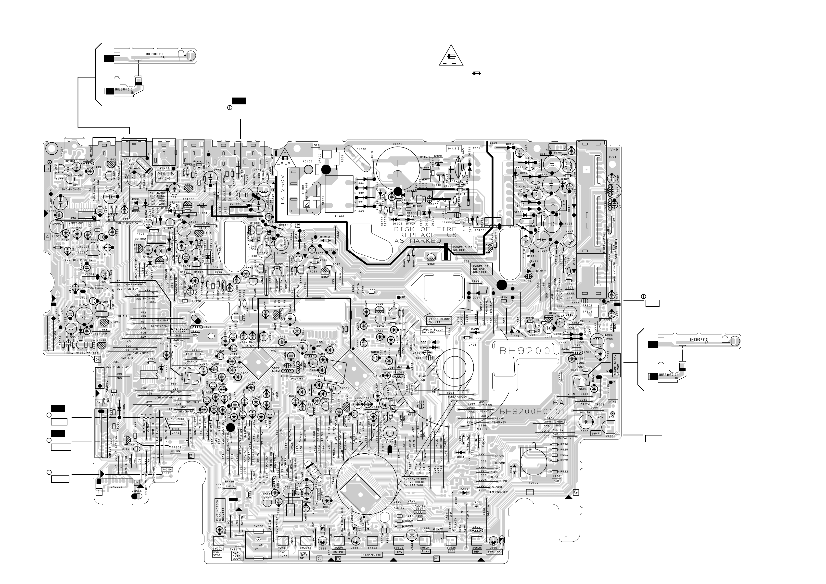
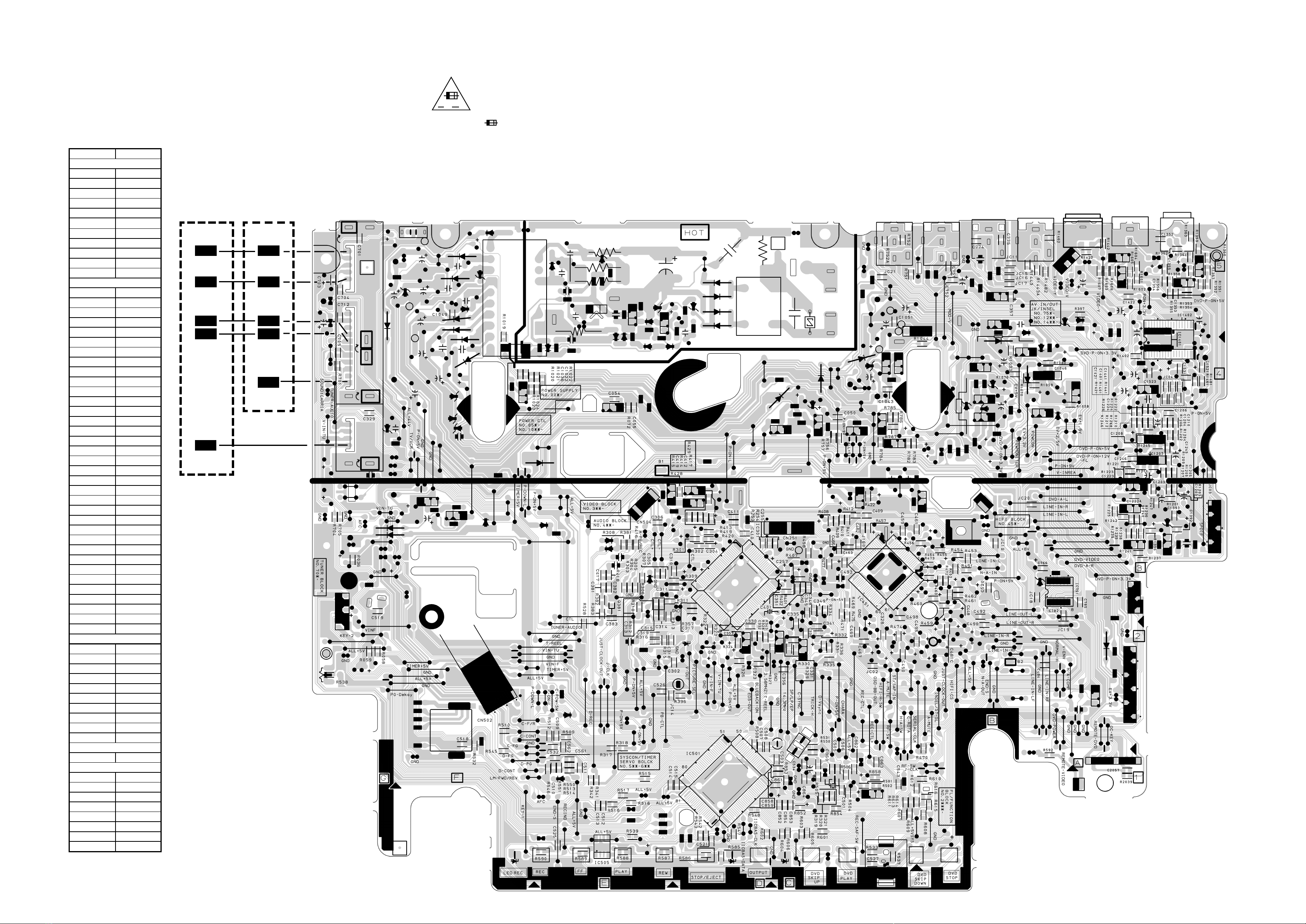
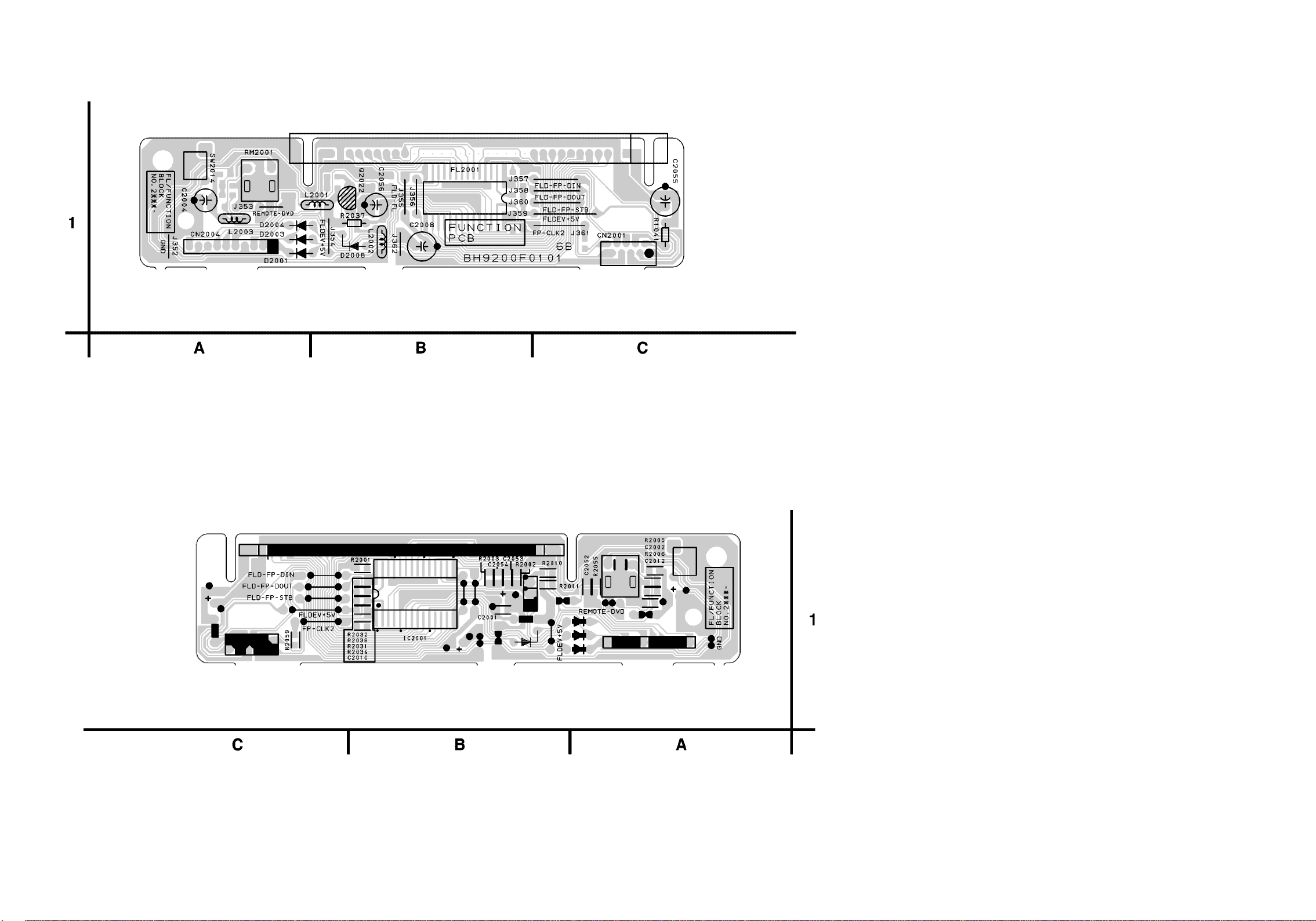
SCHEMATIC DIAGRAMS / CBA’S AND TEST POINTS
Standard Notes
WARNING
Many electrical and mechanical parts in this chassis
have special characteristics. These characteristics
often pass unnoticed and the protection afforded by
them cannot necessarily be obtained by using replace-
ment components rated for higher voltage, wattage,
etc. Replacement parts that have these special safety
characteristics are identified in this manual and its
supplements; electrical components having such fea-
tures are identified by the mark " #" in the schematic
diagram and the parts list. Before replacing any of
these components, read the parts list in this manual
carefully. The use of substitute replacement parts that
do not have the same safety characteristics as speci-
fied in the parts list may create shock, fire, or other
hazards.
Capacitor Temperature Markings
Capacitors and transistors are represented by the fol-
lowing symbols.
Notes:
1. Do not use the part number shown on these draw-
ings for ordering. The correct part number is
shown in the parts list, and may be slightly different
or amended since these drawings were prepared.
2. All resistance values are indicated in ohms
(K=103, M=106).
3. Resistor wattages are 1/4W or 1/6W unless other-
wise specified.
4. All capacitance values are indicated in µF
(P=10-6 µF).
5. All voltages are DC voltages unless otherwise
specified.
Mark Capacity
change rate
Standard
temperature
Temperature
range
(B) ±10% 20°C -25~+85°C
(F) +30 - 80% 20°C -25~+85°C
(SR) ±15% 20°C -25~+85°C
(Z) +30 - 80% 20°C -10~+70°C

2-2 SC_FN2
A V
F
LIST OF CAUTION, NOTES, AND SYMBOLS USED IN THE SCHEMATIC DIAGRAMS ON THE FOLLOWING
PAGES:
1. CAUTION:
FOR CONTINUED PROTECTION AGAINST FIRE HAZARD, REPLACE ONLY WITH THE SAME
TYPE FUSE.
ATTENTION: POUR UNE PROTECTION CONTINUE LES RISQES D'INCELE N'UTILISER QUE
DES FUSIBLE DE MEMO TYPE.
RISK OF FIRE-REPLACE FUSE AS MARKED.
2. CAUTION:
Fixed Voltage (or Auto voltage selectable) power supply circuit is used in this unit.
If Main Fuse (F1001) is blown, first check to see that all components in the power supply circuit are not defec-
tive before you connect the AC plug to the AC power supply. Otherwise it may cause some components in the
power supply circuit to fail.
3. Note:
(1) Do not use the part number shown on the drawings for ordering. The correct part number is shown in the parts
list, and may be slightly different or amended since the drawings were prepared.
(2) To maintain original function and reliability of repaired units, use only original replacement parts which are
listed with their part numbers in the parts list section of the service manual.
4. Wire Connectors
(1) Prefix symbol "CN" means "connector" (can disconnect and reconnect).
(2) Prefix symbol "CL" means "wire-solder holes of the PCB" (wire is soldered directly).
5. Mode: SP
6. Voltage indications for PLAY mode on the schematics are as shown below:
7. How to read converged lines
8. Test Point Information
This symbol means fast operating fuse.
Ce symbole represente un fusible a fusion rapide.
231
5.0
PLAY mode
5.0
Unit: Volts
Indicates that the voltage
is not consistent here.
1-D3
Distinction Area
Line Number
(1 to 3 digits)
Examples:
1. "1-D3" means that line number "1" goes to area "D3".
2. "1-B1" means that line number "1" goes to area "B1".
3
2
1
ABCD
1-B1
1-D3
AREA D3
AREA B1
: Indicates a test point with a jumper wire across a hole in the PCB.
: Used to indicate a test point with a component lead on foil side.
: Used to indicate a test point with no test pin.
: Used to indicate a test point with a test pin.

W1
W2 X2 Y2 Z2 AA2
X1 Y1 Z1 AA1
W3 X3 Y3 Z3 AA3
AUDIO SIGNAL
DATA(AUDIO)
VIDEO SIGNAL
Main 5/5 Schematic Diagram < VCR Section >
2-3 2-4 H9223SCM5
Main 5/5 Schematic Diagram
Ref. No Position
IC1201 X-1
IC1401 Y-3
Q1201 Y-1
Q1202 Y-1
Q1203 Y-1
Q1204 Y-1
Q1351 Z-1
CN1601 W-3
CONNECTORS
ICS
TRANSISTORS

V-OUT
TP751
WF1
C-PB
TP301
WF5
RF-SW
TP302
WF2
CTL
TP303
SW-P
VR501
S-INH
TP502
NOTE :
The voltage for parts in hot circuit is measured using
hot GND as a common terminal.
CAUTION !
Fixed voltage power supply circuit is used in this unit.
If Main Fuse (F001) is blown, check to see that all components in the power supply
circuit are not defective before you connect the AC plug to the AC power supply.
Otherwise it may cause some components in the power supply circuit to fail.
CAUTION
FOR CONTINUED PROTECTION AGAINST FIRE HAZARD,
REPLACE ONLY WITH THE SAME TYPE FUSE.
ATTENTION : POUR UNE PROTECTION CONTINUE LES RISQES
D'INCELE N'UTILISER QUE DES FUSIBLE DE MEMO TYPE.
RISK OF FIRE-REPLACE FUSE AS MARKED.
"This symbol means fast operating fuse."
"Ce symbole reprèsente un fusible à fusion rapide."
A V
FBECAUSE A HOT CHASSIS GROUND IS PRESENT IN THE POWER
SUPPLY CIRCUIT , AN ISOLATION TRANSFORMER MUST BE USED.
ALSO , IN ORDER TO HAVE THE ABILITY TO INCREASE THE INPUT
SLOWLY , WHEN TROUBLESHOOTING THIS TYPE POWER SUPPLY
CIRCUIT , A VARIABLE ISOLATION TRANSFORMER IS REQUIRED.
2-5 2-6 2-7
Main CBA Top View
BH9200AF01016-A
BHB300F01011-A
BHB300F01011-B
Sensor CBA Top View ( Start Sensor )
BHB300F01011-A
BHB300F01011-B
Sensor CBA Top View ( End Sensor )

TYPEB
WF8WF8
WF8WF9
WF8WF10
WF8WF11
WF8WF14
NOTE :
The voltage for parts in hot circuit is measured using
hot GND as a common terminal.
CAUTION !
Fixed voltage power supply circuit is used in this unit.
If Main Fuse (F001) is blown, check to see that all components in the power supply
circuit are not defective before you connect the AC plug to the AC power supply.
Otherwise it may cause some components in the power supply circuit to fail.
CAUTION
FOR CONTINUED PROTECTION AGAINST FIRE HAZARD,
REPLACE ONLY WITH THE SAME TYPE FUSE.
ATTENTION : POUR UNE PROTECTION CONTINUE LES RISQES
D'INCELE N'UTILISER QUE DES FUSIBLE DE MEMO TYPE.
RISK OF FIRE-REPLACE FUSE AS MARKED.
"This symbol means fast operating fuse."
"Ce symbole reprèsente un fusible à fusion rapide."
A V
F
BECAUSE A HOT CHASSIS GROUND IS PRESENT IN THE POWER
SUPPLY CIRCUIT , AN ISOLATION TRANSFORMER MUST BE USED.
ALSO , IN ORDER TO HAVE THE ABILITY TO INCREASE THE INPUT
SLOWLY , WHEN TROUBLESHOOTING THIS TYPE POWER SUPPLY
CIRCUIT , A VARIABLE ISOLATION TRANSFORMER IS REQUIRED.
Note:
The Tuner Unit ( TU701 ) is either type A or type B.
Wave Form will be different. It depends on the type of
tuner used on the unit you are servicing.
WF8WF8
WF8WF9
WF8WF10
WF8WF11
WF8WF14
TYPEA
2-8 2-9 2-10 BH9200F01016-A
Main CBA Bottom View
Main CBA
Ref.No Position
IC301 D-3
IC451 C-3
IC501 D-1
IC751 A-3
IC1001 E-4
IC1002 A-4
IC1003 B-5
IC1004 B-5
IC1006 F-4
IC1201 A-4
IC1401 A-5
Q052 C-4
Q055 C-4
Q056 C-4
Q060 E-4
Q301 D-2
Q302 C-2
Q303 C-2
Q391 B-5
Q421 C-3
Q422 B-3
Q423 E-3
Q424 D-3
Q425 D-3
Q501 C-1
Q503 B-3
Q504 F-3
Q506 D-2
Q760 A-2
Q762 C-4
Q763 C-4
Q1001 E-5
Q1002 C-4
Q1003 E-5
Q1004 B-4
Q1005 B-4
Q1006 C-4
Q1007 B-4
Q1008 E-5
Q1011 B-4
Q1015 A-4
Q1201 A-3
Q1202 A-4
Q1203 A-3
Q1204 A-3
Q1351 A-5
ICS
TRANSISTORS
CONNECTORS
CN251 C-3
CN501 B-3
CN502 F-2
CN504 E-3
CN505 F-3
CN651 F-2
CN1001 A-2
CN1601 A-3
CN2002 A-3
CN2003 A-1
VR501 F-2
TP301 B-2
TP302 B-2
TP303 F-3
TP502 B-2
TP505 F-3
TP506 F-2
TP507 B-3
TP751 C-5
TEST POINTS
VARIABLE RESISTORS

2-11 2-12
Jack CBA Top View Jack CBA Bottom View
BH9200F01016-C

2-13 2-14
Function CBA Top View
Function CBA Bottom View
BH9200F01016-B

3-1 H9223PL
Different parts from original model (EWD2202)
Ref. No. Description Part No.
Mechanical Parts
A1X FRONT ASSEMBLY H9223UD 0VM203688
A2 TOP COVER H9225UD 0VM305415
A4 PANEL, REAR H9223UD 0VM203687
A8 DOOR, CASSETTE H9223UD 0VM413780
A10#LABEL, RATING H9223UD ---------
A15 LABEL, BAR CODE SALES SUPPLY(H9200UD) Not used
A18 LABEL, TELEPHONE NUMBER H5720UD 0VM410319
A20 PANEL, TRAY H9221JD 0VM413420
1B2 DVD MECHA 0838 VCDVM030 N79F1FVM
2B12 PC SHEET H9200UD Not used
2L041 SCREW, C-TIGHT M3X5 BIND HEAD + GBKC3050
S1 GIFT BOX CARTON H9223UD 0VM305602
X1 REMOTE CONTROL UNIT 364/CRC006 NA200UD
X20#OWNER'S MANUAL H9223UD 0VMN03152
X36 RETURN STOP SHEET H9223UD 0VM413703
Electrical Parts
MCV CBA 0VSA12878
C1461 ELECTROLYTIC CAP. 1µF/50V M H7 Not used
C1462 ELECTROLYTIC CAP. 470µF/6.3V M or Not used
ELECTROLYTIC CAP. 470µF/6.3V M Not used
C1481 ELECTROLYTIC CAP. 1µF/50V M H7 Not used
C1482 ELECTROLYTIC CAP. 470µF/6.3V M or Not used
ELECTROLYTIC CAP. 470µF/6.3V M Not used
IC1401 DRIVER FOR DVD(3CH) MM1566AF QSZBA0SMM083
IC1402 DRIVER FOR DVD (6CH) MM1567AJ Not used
JK1403 RCA JACK MSP-213V1-652 PBSN Not used
R1461 CHIP RES.(1608) 1/10W F 300 Ωor Not used
CHIP RES.(1608) 1/10W F 300 ΩNot used
R1462 CHIP RES.(1608) 1/10W J 75 ΩNot used
R1481 CHIP RES.(1608) 1/10W F 300 Ωor Not used
CHIP RES.(1608) 1/10W F 300 ΩNot used
R1482 CHIP RES.(1608) 1/10W J 75 ΩNot used
R1443A CHIP RES.(1608) 1/10W J 75 ΩNot used

Printed in Japan
2002-06-24 HO
WF802 H9223UD

OPEN/CLOSE
STOP
SKIP/REV
PLAY
FWD/SKIP
DVD OPERATION VCR OPERATION
STOP/EJECT
REW PLAY
POWER
VIDEO
AUDIO
F.FWD
REC/OTR
TIMER
SET
VCR/TV
CST.IN
CHANNEL
OUTPUT
L
R
SERVICE MANUAL
Sec. 1: Main Section
ISpecifications
IPreparation for Servicing
IAdjustment Procedures
ISchematic Diagrams
ICBA’s
Sec. 2: Deck Mechanism Section
IStandard Maintenance
IAlignment for Mechanism
IDisassembly/Assembly of Mechanism
IAlignment Procedures of Mechanism
Sec. 3: Exploded views
and Parts List Section
IExploded views
IParts List
EWD2202
DVD PLAYER &
VIDEO CASSETTE RECORDER

IMPORTANT SAFETY NOTICE
Proper service and repair is important to the safe, reliable operation of all
Funai Equipment. The service procedures recommended by Funai and
described in this service manual are effective methods of performing service
operations. Some of these service special tools should be used when and as
recommended.
It is important to note that this service manual contains various CAUTIONS
and NOTICES which should be carefully read in order to minimize the risk of
personal injury to service personnel. The possibility exists that improper ser-
vice methods may damage the equipment. It also is important to understand
that these CAUTIONS and NOTICES ARE NOT EXHAUSTIVE. Funai could not
possibly know, evaluate and advice the service trade of all conceivable ways
in which service might be done or of the possible hazardous consequences of
each way. Consequently, Funai has not undertaken any such broad evalua-
tion. Accordingly, a servicer who uses a service procedure or tool which is not
recommended by Funai must first use all precautions thoroughly so that nei-
ther his safety nor the safe operation of the equipment will be jeopardized by
the service method selected.
Manufatured under license from Dolby Laboratories. "Dolby" and
the double-D symbol are trademarks of Dolby Laboratories.
"DTS" and "DTS Digital Out" are trademarks of Digital Theater Systems Inc.

MAIN SECTION
VIDEO CASSETTE RECORDER
EWD2202
TABLE OF CONTENTS
Specifications. . . . . . . . . . . . . . . . . . . . . . . . . . . . . . . . . . . . . . . . . . . . . . . . . . . . . . . . . . . . . . . . . . . . . . . . . . 1-1-1
Laser Beam Safety Precautions . . . . . . . . . . . . . . . . . . . . . . . . . . . . . . . . . . . . . . . . . . . . . . . . . . . . . . . . . . . 1-2-1
Important Safety Precautions. . . . . . . . . . . . . . . . . . . . . . . . . . . . . . . . . . . . . . . . . . . . . . . . . . . . . . . . . . . . . . 1-3-1
Standard Notes for Servicing . . . . . . . . . . . . . . . . . . . . . . . . . . . . . . . . . . . . . . . . . . . . . . . . . . . . . . . . . . . . . . 1-4-1
Preparation for Servicing . . . . . . . . . . . . . . . . . . . . . . . . . . . . . . . . . . . . . . . . . . . . . . . . . . . . . . . . . . . . . . . . . 1-5-1
Operating Controls and Functions . . . . . . . . . . . . . . . . . . . . . . . . . . . . . . . . . . . . . . . . . . . . . . . . . . . . . . . . . . 1-6-1
Cabinet Disassembly Instructions . . . . . . . . . . . . . . . . . . . . . . . . . . . . . . . . . . . . . . . . . . . . . . . . . . . . . . . . . . 1-7-1
Electrical Adjustment Instructions . . . . . . . . . . . . . . . . . . . . . . . . . . . . . . . . . . . . . . . . . . . . . . . . . . . . . . . . . . 1-8-1
ROM Renewal Mode . . . . . . . . . . . . . . . . . . . . . . . . . . . . . . . . . . . . . . . . . . . . . . . . . . . . . . . . . . . . . . . . . . . . 1-9-1
Block Diagrams . . . . . . . . . . . . . . . . . . . . . . . . . . . . . . . . . . . . . . . . . . . . . . . . . . . . . . . . . . . . . . . . . . . . . . . 1-10-1
Schematic Diagrams / CBA’s and Test Points. . . . . . . . . . . . . . . . . . . . . . . . . . . . . . . . . . . . . . . . . . . . . . . . 1-11-1
Waveforms . . . . . . . . . . . . . . . . . . . . . . . . . . . . . . . . . . . . . . . . . . . . . . . . . . . . . . . . . . . . . . . . . . . . . . . . . . . 1-12-1
Wiring Diagrams . . . . . . . . . . . . . . . . . . . . . . . . . . . . . . . . . . . . . . . . . . . . . . . . . . . . . . . . . . . . . . . . . . . . . . 1-13-1
System Control Timing Charts . . . . . . . . . . . . . . . . . . . . . . . . . . . . . . . . . . . . . . . . . . . . . . . . . . . . . . . . . . . . 1-14-1
IC Pin Function Descriptions . . . . . . . . . . . . . . . . . . . . . . . . . . . . . . . . . . . . . . . . . . . . . . . . . . . . . . . . . . . . . 1-15-1
Lead Identifications . . . . . . . . . . . . . . . . . . . . . . . . . . . . . . . . . . . . . . . . . . . . . . . . . . . . . . . . . . . . . . . . . . . . 1-16-1
Sec. 1: Main Section
ISpecifications
IPreparation for Servicing
IAdjustment Procedures
ISchematic Diagrams
ICBA’s

1-1-1 H9200SP
SPECIFICATIONS
< VCR Section >
Note: Nominal specs represent the design specs. All units should be able to approximate these – some will exceed
and some may drop slightly below these specs. Limit specs represent the absolute worst condition that still might
be considered acceptable; In no case should a unit fail to meet limit specs.
Description Unit Minimum Nominal Maximum Remark
1. Video
1-1. Video Output (PB) Vp-p 0.8 1.0 1.2 SP Mode
1-2. Video Output (R/P) Vp-p 0.8 1.0 1.2
1-3. Video S/N Y (R/P) dB 40 45 SP Mode,
W/O Burst
1-4. Video Color S/N AM (R/P) dB 37 41 SP Mode
1-5. Video Color S/N PM (R/P) dB 30 36 SP Mode
1-6. Resolution (PB) Line 230 245 SP Mode
2. Servo
2-1. Jitter Low µsec 0.07 0.12 SP Mode
2-2. Wow & Flutter % 0.3 0.5 SP Mode
3. Normal Audio
3-1. Output (PB) dBV -9 -6 -3 SP Mode
3-2. Output (R/P) dBV -9 -6 -1.5 SP Mode
3-3. S/N (R/P) dB 36 41 SP Mode
3-4. Distortion (R/P) % 1.0 4.0 SP Mode
3-5. Freq. resp (R/P) at 200Hz dB -11 -4 SP Mode
(-20dB ref. 1kHz) at 8kHz dB -14 -4 SP Mode
4. Tuner
4-1. Video output Vp-p 0.8 1.0 1.2 E-E Mode
4-2. Video S/N dB 39 42 E-E Mode
4-3. Audio output dB -10 -6 -2 E-E Mode
4-4. Audio S/N dB 40 46 E-E Mode
5. Hi-Fi Audio
5-1. Output dBV -12 -8 -4 SP Mode
5-2. Dynamic Range dB 70 85 SP Mode
5-3. Freq. resp (6dB B.W) Hz 20 ~ 20K SP Mode

1-1-2 H9200SP
< DVD Section >
NOTES:
1. All Items are measured without pre-emphasis unless otherwise specified.
2. Power supply : AC120 V 60 Hz
3. Load imp. : 100 K ohm
4. Room ambient : +25 °C
ITEM CONDITIONS UNIT NOMINAL LIMIT
1. Video Output 75 ohm load Vpp 1.0
2. Coaxial Digital Out mVpp 500
3. Audio (PCM)
3-1. Output Level 1kHz 0dB Vrms 2.0
3-2. S/N dB 85
3-3. Freq. Response
DVD fs=48kHz 20~22kHz dB ± 2
CD fs=44.1kHz 20~20 kHz dB ± 2
3-4. THD+N 1 kHz 0dB % 0.005

1-2-1 DVD_LASER
Drive Mecha Assembly
Laser Beam Radiation
Laser Pickup
Turntable
LASER RADIATION
WHEN OPEN. DO NOT
STARE INTO BEAM.
CAUTION
LASER BEAM SAFETY PRECAUTIONS
This DVD player uses a pickup that emits a laser beam.
The laser beam is emitted from the location shown in the figure. When checking the laser diode, be sure to keep
your eyes at least 30cm away from the pickup lens when the diode is turned on. Do not look directly at the laser
beam.
Caution: Use of controls and adjustments, or doing procedures other than those specified herein, may result in
hazardous radiation exposure.
Do not look directly at the laser beam coming
from the pickup or allow it to strike against
your skin.
Location: Inside Top of DVD mechanism.

1-3-1 DVD_SFN1
IMPORTANT SAFETY PRECAUTIONS
Product Safety Notice
Some electrical and mechanical parts have special
safety-related characteristics which are often not evi-
dent from visual inspection, nor can the protection
they give necessarily be obtained by replacing them
with components rated for higher voltage, wattage,
etc. Parts that have special safety characteristics are
identified by a #on schematics and in parts lists. Use
of a substitute replacement that does not have the
same safety characteristics as the recommended
replacement part might create shock, fire, and/or other
hazards. The Product’s Safety is under review contin-
uously and new instructions are issued whenever
appropriate. Prior to shipment from the factory, our
products are carefully inspected to confirm with the
recognized product safety and electrical codes of the
countries in which they are to be sold. However, in
order to maintain such compliance, it is equally impor-
tant to implement the following precautions when a set
is being serviced.
Precautions during Servicing
A. Parts identified by the #symbol are critical for
safety. Replace only with part number specified.
B. In addition to safety, other parts and assemblies
are specified for conformance with regulations
applying to spurious radiation. These must also be
replaced only with specified replacements.
Examples: RF converters, RF cables, noise block-
ing capacitors, and noise blocking filters, etc.
C. Use specified internal wiring. Note especially:
1)Wires covered with PVC tubing
2)Double insulated wires
3)High voltage leads
D. Use specified insulating materials for hazardous
live parts. Note especially:
1)Insulation tape
2)PVC tubing
3)Spacers
4)Insulators for transistors
E. When replacing AC primary side components
(transformers, power cord, etc.), wrap ends of
wires securely about the terminals before solder-
ing.
F. Observe that the wires do not contact heat produc-
ing parts (heatsinks, oxide metal film resistors, fus-
ible resistors, etc.).
G. Check that replaced wires do not contact sharp
edges or pointed parts.
H. When a power cord has been replaced, check that
5 - 6 kg of force in any direction will not loosen it.
I. Also check areas surrounding repaired locations.
J. Be careful that foreign objects (screws, solder
droplets, etc.) do not remain inside the set.
K. Crimp type wire connector
The power transformer uses crimp type connectors
which connect the power cord and the primary side
of the transformer. When replacing the transformer,
follow these steps carefully and precisely to pre-
vent shock hazards.
Replacement procedure
1)Remove the old connector by cutting the wires at a
point close to the connector.
Important: Do not re-use a connector. (Discard it.)
2)Strip about 15 mm of the insulation from the ends
of the wires. If the wires are stranded, twist the
strands to avoid frayed conductors.
3)Align the lengths of the wires to be connected.
Insert the wires fully into the connector.
4)Use a crimping tool to crimp the metal sleeve at its
center. Be sure to crimp fully to the complete clo-
sure of the tool.
L. When connecting or disconnecting the internal con-
nectors, first, disconnect the AC plug from the AC
outlet.

1-3-2 DVD_SFN1
Chassis or Secondary Conductor
dd'
Primary Circuit Terminals
AC Voltmeter
(High Impedance)
Exposed Accessible Part
BEarth Ground
Power Cord Plug Prongs
Z
1.5k
0.15 F
Safety Check after Servicing
Examine the area surrounding the repaired location for
damage or deterioration. Observe that screws, parts,
and wires have been returned to their original posi-
tions. Afterwards, do the following tests and confirm
the specified values to verify compliance with safety
standards.
1. Clearance Distance
When replacing primary circuit components, confirm
specified clearance distance (d) and (d’) between sol-
dered terminals, and between terminals and surround-
ing metallic parts. (See Fig. 1)
Table 1 : Ratings for selected area
Note: This table is unofficial and for reference only.
Be sure to confirm the precise values.
2. Leakage Current Test
Confirm the specified (or lower) leakage current
between B (earth ground, power cord plug prongs)
and externally exposed accessible parts (RF termi-
nals, antenna terminals, video and audio input and
output terminals, microphone jacks, earphone jacks,
etc.) is lower than or equal to the specified value in the
table below.
Measuring Method (Power ON) :
Insert load Z between B (earth ground, power cord
plug prongs) and exposed accessible parts. Use an
AC voltmeter to measure across the terminals of load
Z. See Fig. 2 and the following table.
AC Line Voltage Clearance Distance (d) (d’)
120 V ≥3.2mm (0.126 inches)
Table 2: Leakage current ratings for selected areas
Note: This table is unofficial and for reference only. Be sure to confirm the precise values.
AC Line Voltage Load Z Leakage Current (i) Earth Ground (B) to:
120 V 0.15µF CAP. & 1.5kΩ RES.
Connected in parallel i≤0.5mA Peak Exposed accessible parts
Fig. 1
Fig. 2
Other manuals for WF802
1
Table of contents
Other Symphonic DVD Player manuals

Symphonic
Symphonic SD300D User manual

Symphonic
Symphonic WF803 User manual

Symphonic
Symphonic SD200E User manual

Symphonic
Symphonic SD200E User manual

Symphonic
Symphonic DVD/CD Player User manual

Symphonic
Symphonic RSMSD125 User manual

Symphonic
Symphonic CSHP80G User manual

Symphonic
Symphonic WF104 User manual

Symphonic
Symphonic SD300D User manual