Synergy SG900 Quick start guide

1
Synergy Grill 900
User & Engineer
Installation &
Conversion
Guide

2
Index:
Description Page Number/Section
Important Information 3-4
Installation 5-9 / Section 1
Commissioning 9 / Section 2
Converting Gas Types 10-13 / Section 3
Section 1.1
Unpacking
Section 1.2 Technical Information
Section 1.3 Sitting
Section 1.4 Ventilation
Section 1.5 Gas Supply
Section 1.6 Electrical Supply
Section 1.7 Water Supply
Section 1.8 Starting up and Shutting Down
Section 2.1
Testing and Purging
Section 2.2 Checking Pressures
Section 2.3 Gas Soundness
Section 3.1.1
Changing Injectors for LPG
Section 3.1.2 Fully Opening the Gas Valve Regulator with Blocking Pin for
LPG
Section 3.1.3 LPG Data Plate
Section 3.2 How to Check the Appliances Internal Gas Valve is Fully
Open/Out of Action

3
Section 3.3.1 Changing Injectors for Natural Gas
Section 3.3.2 Reinstating the Internal Gas Valve Regulator for Natural Gas
Section 3.3.3 Nat Gas Data Plate

4
Important Information
It is important that the installation and servicing instructions throughout this
booklet are followed as any failure to do so may invalidate the warranty of this
appliance.
This appliance must be installed by a qualified Gas Safe Registered engineer. Every
engineer carries a Gas Safe Register ID Card and it is advised you ask to see this
before any work is carried out on installations or converting for use with other gases.
Please pay particular attention to: Gas Safety Regulations
Health & Safety Law
Local & National Building Regulations
Fire Precautions Act
This appliance is supplied with a one year parts and labour warranty.
Do not use an external in-line Gas Governor to set the pressure, please do so with
the appliances internal gas valves.
This appliance is CE marked declaring the compliance with EC directives. The Gas
Types and Pressures for the destined country are stated on the appliance Data Plate.
The instructions throughout this document are only valid in the countries stated on
the Data Plate
Unless otherwise stated this unit is set for G20 (Natural Gas), however your Gas Safe
engineer MUST confirm the Outlet Pressure is 15mbar before commissioning the unit.
LPG conversion kits are located within your documentation.
Do not remove the Ceramic Blocks from the unit when moving/installing - putting
the blocks back in may damage the thermal paper and block the vortex holes.
There is a metal divider plate in the ceramic bedding – this must not be removed or
the air flow and heat distribution will not work to full effect.
This appliance must be positioned in a draught free position with good ventilation -
cooling air blowing onto the grill can distort the vortex heat distribution.

5
It is very important to not spray aerosols, or any other flammable gases, near this
appliance whilst it is in operation; doing so may cause injury to user.
Active Food Systems advise that you season the cooking bars before placing any
food on them; this will remove any manufacturing oils and also smooth the natural
pitting created from freshly cast mouldings. Seasoning your cooking bars with a
light oil, such as vegetable oil, can smooth out the pitting and stop any food from
sticking. Fresh, unoiled cast iron cooking bars are also prone to rust if you do not
season them from the start. First week/use rusting of cooking bars from lack of bar
seasoning will not be covered by warranty.
Active Food Systems highly recommends keeping a gap between the cooking bars
and the top panel to help stop Thermal Conductance, and so help keep the unit
slightly cooler to touch.
This appliance is a professional piece of kit and as such is only for professional use
and should only be used by qualified people.

6
Section 1 – Installation:
1.1 Unpacking:
Upon delivery of your appliance, carefully remove all the protective plastic and keep
the documentation to one side – within your documentation, amongst other
important information, is the LPG Data Plate sticker and LPG Conversion Kit which
will be needed if your supply gas is not natural gas; a natural gas data plate will
already be on your unit.
Please fill in your warranty registration and return to Active Food Systems to start
your warranty.
This unit is heavy – do not attempt to lift with less than four people.
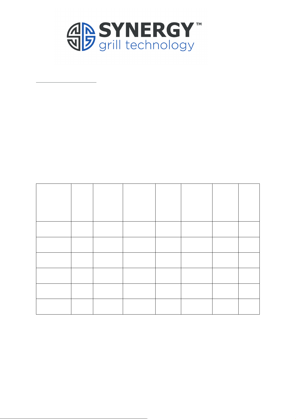
1.2 Technical Information:
Gas Type
Width
Depth
(Not
Including
Rear Gas
Inlet
Height
(Including
Rear Up-
Stand)
Weight
Gas Inlet
coming
off
appliance
Injector
Size
Flue
Type
G20
(Natural)
905
646
530
115kg
¾” BSP
Male
2.2
A3
G31
(Propane)
905
646
530
115kg
¾” BSP
Male
1.5
A3
G30
(Butane)
905
646
530
115kg
¾” BSP
Male
1.5
A3
G30/G31
(Mix)
905
646
530
115kg
¾” BSP
Male
1.5
A3
G25
(Natural)
905
646
530
115kg
¾” BSP
Male
2.2
A3
G25.3A
(Natural)
905
646
530
115kg
¾” BSP
Male
2.2
A3

7
Model Reference
Synergy SG900
Reference Gas
G20
G25
G25.3A
G30
Categories
I2H (20)
I2L (25)
I2EKH
(25)
I3+ (28-30/37) ,
I3B/P (30)
Total Nominal NET heat Input
kW
11.4
11.0
11.0
12.6
Total nominal rate m3/h
1.206
1.32
1.28
0.994 kg/h
Nominal NET heat Input kW/
burner
5.7
5.7
5.7
6.3
Nominal Rate / burner m3/h
0.603
0.69
0.65
0.497 kg/h
Burner pressure mbar
15.0
17.1
17.1
N/A*
No of burners
2
Orifice size (mm) per burner
2.2
1.5
Electrical supply
230V ~ 50Hz<1KW
*Regulator is fully open with blocking pin

8
1.3 Sitting:
The grill may be mounted on:
Bench
Fridges
Single or Multiple units (available from your supplier)
This unit does not require a minimum safety distance from surrounding surfaces, but
we recommend you follow these distances below to ensure no overheating of
surfaces.
Sides – 6 inches
Rear – 10 inches
Above – 47 inches
Please ensure the power lead is not ever stretched.
Please ensure the front panel and underneath the unit is kept clear to allow critical
airflow and access to the Synergy Grill. This can be blocked by tea towels, trays or
anything thin enough to ‘store’ under the unit.
1.4 Ventilation:
The unit must be installed in a draught free position. Adequate ventilation must be
provided to ensure complete removal of combustion by-products which may be
harmful to health. Recommendations for Ventilation of Catering Appliances are
given in BS5440:2.
For multiple unit installations, the requirements for individual appliances should be
added together.
Installation should be made in accordance with local and/or national regulations
applicable at the time.
Positioning the unit below a ventilated canopy is the most suitable arrangement.

9
1.5 Gas Supply:
The incoming gas supply must be sufficient to supply the unit to fully working
pressure without excessive drop; to do this we recommend using a ¾” supply
pipe/catering hose. The installation pipes should be fitted in accordance with
IGE/UP/2.
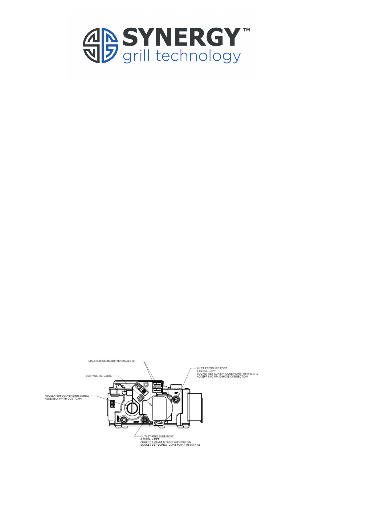
Inlet pressure drop can be measured via the Inlet Pressure Post on the unit’s internal
gas valve.
Gas supply tubing must comply with the current national requirements in force and
should be periodically examined and replaced as necessary.
An isolating cock must be located close to the appliance to allow a fast shut off
during an emergency or routine servicing.
1.6 Electrical Supply:
This unit is supplied via a 5A 3-pin plug at 240v.
This unit must be earthed or the appliance will not work. This unit relies on Flame
Rectification to detect the flame. A good earth allows a path to ground via the flame
to occur which is critical for the appliance to work. Active Food Systems
recommends extra earth bonding where possible.
If the power supply to the appliance fails momentarily, the internal gas valves will
close stopping any gas escaping. The appliance will shut down for around 30
seconds before the fan speeds have slowed sufficiently for the unit to self-power-
up again. You do not need to reset any buttons.

10
If the power supply to the appliance fails in events such as a power-cut, please
switch off the appliance at the front switch. Do not walk away from a grill that has
no power but with the switch turned on. Doing so could cause a fire is something
flammable is left unattended near the appliance and the power then comes back on
and reignites the grill.
1.7 Water Supply:
Not applicable for this appliance.
1.8 Starting up and Shutting Down
The Synergy Grill uses an automated ignition system via the Front Switches. Each
Front Green Rocker Switch is assigned in order of each burner – Left Switch controls
the Left Burner and so forth. Pressing this switch will cause the appliance to run
through a start-up procedure before self-igniting around 10 second later. If no
ignition occurs please refer to Section 4 on the fault finding page.
To shut down simply turn the unit off using the front Green Rocker Switch and the
appliance will cut all power to the appliance and shut the internal gas valve ready to
be switched on again.
2 Commissioning
2.1 Testing and Purging:
Please make sure all air is purged from the pipes before checking pressures.

11
2.2 Checking Pressures:
A) To gain access to the internal gas valve please remove the top collar from
the unit and place to one side, you should now have access to four screws
securing the front panel to the unit. Remove these four screws and place
the front panel underneath the appliance being careful not to pull on any
front panel wires.
B) Unscrew the Inlet Pressure Post with a 2.5mm Allen key and connect your
manometer to make sure the supply pressure is consistent with your gas
type. Once happy with the pressure, remove your manometer and tighten
up the Inlet Pressure Post.
C) Unscrew the Outlet Pressure Post with a 2.5mm Allen key and connect
your manometer.
D) Turn on the unit, making sure any packaging is free from the burner, and
adjust the valve until gas pressure reads 15mbar.
YOU MUST ZERO YOU MANOMETER ONCE THE UNIT IS RUNNING
.
When the appliance starts up, the fan pressure in the system will cause
the manometer to increase by around 0.7 to 1.0 mbar before any gas starts
flowing, so when the gas valve opens the manometer will increase again.
SO, if you have 1.0mbar of fan pressure already showing and the Gas Valve
opens and you then increase the final pressure to 15.0 mbar you only
actually have 14.0mbar of gas pressure; the unit will run cold.
To correctly
adjust the pressure, turn the grill on, let it ignite with a steady flame.
Turn OFF the GAS VALVE (not the Grill) using the switch on the Valve
(the unit should then start attempting to reignite) and zero your
manometer so its reads ZERO and then turn the Gas Valve back on
.
The pressure displaying now on your manometer is only the Gas Pressure
,
not the Air and Gas. Changing of pressure is achieved by removing the
Brass Regulator Cover Screw and adjust/screw the white lug inside – anti
clockwise lowers pressure, clockwise increases it. Once outlet pressure
has been reached, retighten the Brass Regulator Cover Screw, remove
manometer and retighten the Outlet Pressure Post.
Once the gas pressure has been set the flame length should be a steady 10mm
around the burner, if the flame is different please make sure the Gas Jet & Gas Types
correspond to each other. You should not need to adjust the air speed to this unit.

12
2.3 Gas Soundness:
After the unit has been pressure checked, test all integral gas carrying joints and
components for gas soundness using relevant gauges.
3 Converting to Different Gas Types
LPG conversion kits can be found in your documentation. Within these kits are 3 x
1.5mm jets, three white springs and three blocking pins and springs.
3.1.1 Changing Injectors for LPG:
A) Carefully unscrew the 4 retaining hexagonal screws holding each burner
using a 7mm socket.
B) Remove the Natural Gas 2.2mm jet using a 9mm socket and keep in a safe
place in case you need to convert back to Natural Gas, and replace with
1.5mm Jet. Screw down the burner again. A new Gasket may be required.
3.1.2 Fully Opening the Gas Valve Regulator with Blocking Pin for LPG:
A) Remove the Brass Regulator Cover Screw and put to one side.
B) Screw the Plastic Regulator Adjustment Screw in all the way until you feel
light resistance – do not over tighten.
C) Take the Blocking Pin and Spring from your conversion kit and place the
Blocking Pin through the centre of the Spring. Now insert this through the
centre of the Plastic Regulator Adjustment Screw.
D) Replace the Brass Regulator Cover Screw.

13
3.1.3 LPG Data Plate:
Remove the LPG Data Plate from the documents supplied with this appliance and
cover over the NAT GAS Data Plate which can be found on this unit.
This unit is now ready to be used for G30, G31 &G30/G31 gas types.
3.2 How to Check the Appliances Internal Gas Valve is Fully Open/Out of
Action:
The table provided in the Technical Information section (1.2) gives information on
the supply pressures of different gas types. Please ensure the valve is sufficiently
open by using a manometer on the Outlet Pressure Post pressure (with the burner
lit) to check the reading is as close to the supply pressure as possible. If the outlet
pressure point has a significant drop in pressure from the inlet, please go through
step 3.1.2 again.
3.3 Converting to Natural Gas:
Natural Gas Jets (2.2mm) should have been kept in a safe place when you originally
converted from Natural Gas to LPG. If you have lost these parts, please contact
Active Food Systems.
If your appliance was originally requested as LPG and you wish to convert to Natural
Gas, the relevant conversion kit will be in your documentation.
3.3.1 Changing Injectors for Natural Gas:
A) Carefully unscrew the 4 retaining hexagonal screws holding each burner
using a 7mm socket.
B) Remove the LPG 1.5mm jet using a 9mm socket and keep in a safe place
in case you need to convert back to LPG, and replace with 2.2mm Jet.
Screw down the burner again. A new Gasket may be required.

14
3.3.2 Reinstating the Internal Gas Valve Regulator for Natural Gas:
A) Remove the Brass Regulator Cover Screw and put to one side.
B) Take out the Blocking Pin and Spring from the centre of the Plastic
Regulator Adjustment Screw and keep safe for when you need to convert
back.
C) Connect your manometer to the Outlet Pressure Post (Follow steps 2.2 C
& D) and set burner to 15mbar.
D) Replace the Brass Regulator Cover Screw.
Nat Gas Data Plate:
Remove the Nat Gas Data Plate from the documents supplied with this appliance
and cover over the LPG Data Plate which can be found on this unit.
This unit is now ready to be used for G20, G25 & G25.3A Gas types.

15
Synergy Grill 900
User & Engineer
Servicing &
Cleaning
Guide

16
Index:
Description Page Number/Section
Important Information 15
General Tools Required 15
Servicing Your Synergy Grill 16-19 / Section 4
Fault Finding Flow Chart 20 / Section 5
Wiring Diagram 21 / Section 6
Daily Cleaning 22
Spares List 23-24 / Section
7
Installation Tips and Advice for Gas Installation Engineer 25
Section 4.1
Flame Dropping Out Through Service
Section 4.2 Changing an Ignitor
Section 4.3 Changing a Valve
Section 4.4 Changing a MicroGas Controller
Section 4.5 Changing a Fan
Section 4.6 Burner & Injector Cleaning
Section 4.7 Any Other Problems
Section 5.1
End of Service Cleaning
Section 5.2 Daily Morning Cleaning

17
Important Information
All internal servicing work on this appliance is to be done via the front panel and by
a certified engineer. Please make sure access to the front panel and directly under
the grill is always kept clear.
Please ensure the Gas Isolating Valve and Electrical Supply has been switched off
before any service work is carried out.
We recommend the appliance is cold before work is started. If possible, please book
your engineer in for an AM service before the unit is switched on for greater ease of
work. If the appliance must be worked on whilst it is still hot always use heat
protective gloves when handling hot parts on and below the cooking surface.
General Tools Required:
2.5mm Allen Key (Gas Pressure post)
3mm Allen Key (Ignitor)
5mm Allen Key (Fan)
Flat Headed Screwdriver (Brass Regulator Cover Screw & Plastic
Regulator Adjustment Screw)
Pozi 2 Screwdriver (General Screws Throughout)
Socket Set – 7 & 9mm (Burner Bolts & Jets)
Adjustable Spanner (internal Gas Valve Removal)
Manometer (Gas Pressures)
Wire Brush (Burner and Ignitor Cleaning)

18
4 Servicing Your Synergy Grill:
4.1 Flame Dropping Out Throughout Service:
If you have noticed the appliance Burner Flame has started dropping out during
service, and has been getting worse over time, you need to make sure the Flame
Detector on the unit is free from debris.
This appliance relies on Flame Rectification to determine whether the Burner Flame
is lit or not. The internal MicroGas controller senses the required electrical circuit is
completed via the ions in the Burner Flame completing the circuit - this completed
circuit keeps the Internal Gas Valve open and the gas flowing. If no signal is received
the gas will shut off causing the system to lock out. The detection system will send
a False Signal back to the Microgas Controller if the electrode is contaminated with
salts, fats and oils.
To stop this simple problem, we recommend a Daily Cleaning Regime of removing
the Cast Iron Cap and Ceramic Ring from around the burner and using a damp (not
wet) cloth to remove any build-up, no matter how small, of salts and oils from the
White Ceramic of the igniter/flame sensor. The please put back the Cap and Ring
and continue onto vacuuming the larger ceramics.
If you are still having problems with the Burner Flame dropping out during service
after you have thoroughly cleaned the Flame Detector please contact Active Food
Systems.
4.2 Changing an Ignitor:
Remove the grill top panel to access the screws holding the panel in place (Figure
1).
Figure 1. Figure 2.

19
The ignitor can be removed by loosening the screw seen in Figure 2.
The replacement ignitor can be replaced and secured in the same way the faulty one
was removed.
If the reported problem persists, please contact Active Food Systems.
4.3 Changing a Valve:
You should only have to change a valve if you switch on your appliance and there is
no ignition sequence and the red front panel light illuminates after roughly 15
seconds. If the ignition sequence begins (the ignitor sparks) but no flame appears
from the burner and then the red light comes on after the unit has attempted this
three times you must check: the gas supply has not dropped coming from the Outlet
Port on the internal Gas Valve (2.2 C & D), nothing is blocking the Burner or the Gas
is connected properly.
Remove the grill top panel to access the screws holing the panel in place (Figure 1).
Please make sure the internal valve switch is ON. If the valve is OFF, please switch
ON and try turning the unit on again. If the grill now lights you do not need to
change the valve.
Figure 3
Remove the valve by loosening the In, Out, and Injector pipe nuts and the two screws
behind the valve bracket (Figure 3). Once these have been undone please remove
the faulty Gas Valve and insert the replacement valve, reversing the above steps
until all fixings are gas tight.

20
After the unit has been lit please test all integral gas carrying joints and components
for gas soundness using relevant gauges.
If the problem persists, please contact Active Food Systems.
4.4 Changing a MicroGas Controller:
Changing a MicroGas controller should be attempted if you: switch the front Green
Rocker Switch on but it does not initiate the appliances fan to start up – if the front
panel is not down at the time please wait up to 20 seconds before you can hear the
fan noise.
Remove the grill top panel to access the screws holding the panel in place (Figure
1).
Remove the MicroGas controller by disconnecting all wires and harnesses, and
loosening the two screws securing the controller (Figure 4). Before swapping out
the whole MicroGas controller, firstly perform a continuity test to make sure it is not
just the 20x5 4A fuse that has blown.
Figure 4
The replacement MicroGas controller can be fitted in the reverse order the faulty
controller was removed.
If the problem persists, please contact Active Food Systems.
This manual suits for next models
3
Table of contents
Popular Grill manuals by other brands

Backyard
Backyard CBT1704W-C Series owner's manual

Camp Chef
Camp Chef PG20CT V2 Warning & instruction booklet

Dimplex
Dimplex PowerChef TBQ-120-REG owner's manual

OBH Nordica
OBH Nordica STEAKHOUSE BBQ CONTACT Instructions for use

SAPIRHOME
SAPIRHOME SP-1015-F instruction manual

Traeger
Traeger BBQ124 owner's manual

Electrolux
Electrolux FN30LP/NG Use & care manual

Jata electro
Jata electro GR266 INTRUCTIONS OF USE

Char-Broil
Char-Broil 463247310 Product guide

EDM Product
EDM Product 07643 instruction manual

Panini
Panini XL Instructions for use and installation

TREVIDEA
TREVIDEA G3 FERRARI LAVICA BLACK G10162 user manual