System 180 Modular furniture system User manual

System 180 GmbH · Ernst-Augustin-Str. 3 · 12489 Berlin, Germany · phone +49 30.788 58 41 · contact@system180.com · system180.com · V. 06-08-20
Assembly Manual

System 180 GmbH · Ernst-Augustin-Str. 3 · 12489 Berlin, Germany · phone +49 30.788 58 41 · contact@system180.com · system180.com · V. 06-08-20
1. System structure
1.1 Basic structure
1.1.1 Before you start …
1.1.2 Par ts
1.1.3 System measurements
1.1.4 Assembly method
1.1.5 Vertical & horizontal offset of component parts
1.1.6 Assembly of corner nodes at bottom
1.1.7 Assembly of central nodes
1.1.8 Assembly of corner nodes at top
1.1.9 Special rule for module with depth T210
1.2 Surfaces
1.2.1 System bases
1.2.2 Connecting bar for work surface/system base
1.2.3 Side panels
1.2.4 Rear / Front panelling
1.2.5 System base panel with bracket for pull-out shelving
1.2.6 Partition walls
2. Accessories
2.1 Doors
2.1.1 Before you start …
2.1.2 Overview of types and handles
2.1.3 Lockable doors
2.1.3.1 Assembly of stop brackets for doors/drawers
2.1.3.2 Lower locking handle
2.1.4 Mounting doors
2.1.5 Adjustment
2.1.6 Damping
2.1.7 Retrofit doors
2.2 Drawers
2.2.1 Before you start ...
2.2.2 Type overview
2.2.3. Lockable drawers
2.2.3.1 Assembly of Stop brackets for doors/drawers
2.2.3.2 Adapter for pull-out lock
2.2.4 Mounting combined fronts (with door under drawer)
2.2.5 Inserting and removing drawers
2.2.6.1 Horizontal and vertical adjustment
2.2.6.2 Angle of inclination at front
2.2.7 Replacement of drawer front
2.2.8 Retrofitting drawers
2.2.8.1 Retrofitting drawers (e.g. for 2 x 180 mm height)
2.2.8.2 Retrofitting of extracts Positions Height 720
2.3 Wardrobe rails
2.3.1 Wardrobe rail vertical to the front
2.3.1.1 Assembling the structural parts
2.3.1.2 Mounting the rail
2.3.2 Wardrobe rail for shelf panel with cable outlets
2.3.3 Wardrobe rail parallel to front
2.4 Shelf
2.4.1 Shelf
2.4.2 Shelf, reinforced
2.4.3 Pull-out shelf assembly
2.4.4 Diagonal shelf
2.5 Hanging folder filer
2.5.1 Adaptive side panel
2.5.1.1 Adaptive side panel H 360/T 430
2.5.1.2 Adaptive side panel H 720/T 430
2.5.2 Assembling the hanging folder filing system
2.6 Magazines (with small niches)
2.6.1 Inserting the base panel
2.6.2 Inserting partitions
2.7 Cable management
2.7.1 Types and assembly
2.7.2 Device box
2.7.2.1 Device box assembly
2.7.2.2 Monitor holder
2.7.3 Device insert assembly
2.7.4 Device top assembly
2.8 Base panels using Rafix connectors
2.9 The brochure display
2.10 Wall Mounting
2.10.1 Tilt protection
2.10.2 Wall suspension
3. Units
3.1 RackPod
3.1.1 RackPod assembly
3.1.2 Assembly S, L, H
3.1.3 Mounting leveling foot and casters
3.1.4 Storage space
3.1.5 Multibox
3.1.6 Cable trough
3.2 CoatRack
3.3 Design Thinking Line®
3.3.1 DT-Line Whiteboard
3.3.1.1 Whiteboard M structure
3.3.1.2 Whiteboard partially assembled
3.3.1.3 Flipchart bracket and pen tray
3.3.2 DT-Line WallRails
3.3.2.1 WallRail
3.3.2.2 WallRail PLUS
3.3.3 DT-Line Table T6
3.3.3.1 DT-Line Table T6 assembling two halves of the frame
3.3.3.2 DT-Line Table T6 transportation lock
3.3.3.3 DT-Line T6 table partially assembled 1/2
3.3.3.3 DT-Line T6 table partially assembled 2/2
3.3.3.4 DT-Line Table T4 S Assembly
3.3.3.5 DT-Line ToolRack S Angle Plates
Contents

System 180 GmbH · Ernst-Augustin-Str. 3 · 12489 Berlin, Germany · phone +49 30.788 58 41 · contact@system180.com · system180.com · V. 06-08-20
3.4 K table system
3.4.1 K table system racks
3.4.1.1 M id d le fo ot
3.4.1.2 Assembly halved frame for transport
3.4.1.3 Slotted table legs
3.4.2 K table system panels
3.4.2.1 Table top mounting standard
3.4.2.2 Table top mounting cover panel joint over profile
3.4.2.3 Assembly instruction bolts
3.4.3 K table system bases
3.4.4 Height compensation articulated feet
3.4.5 K table system panels
3.5 CF/CR-Container
3.6 Lunar table range
3.6.1 Lunar tabletop, partial assembly
3.6.2 Height compensation articulated feet
3.7 Bridge table range
3.7.1 Bridge 970x2050
3.7.1.1 Bridge 970x2050 assembly on casters
3.7.1.2 The two halves of the Bridge 970x2050 frame
3.7.1.3 Bridge 970x2050 tabletop, partial assembly
3.7.2 Bridge 970x2590
3.7.2.1 Bridge 970x2590 assembly on casters
3.7.2.2 Bridge 970x2590 tabletop, partial assembly
3.8 BridgePro
3.9 Sit/Stand desk
3.9.1 Sit/Stand desk partial assembly
3.9.2 Sit/Stand desk electricity supply
3.10 Bleachers moduls SitUp
3.10.1 SitUp ST
3.10.2 SitUp CE 45
3.10.3 SitUp CX 45
3.11 FlexBoard Pro
3.11.1 Flex Rai l
3.11.2 WallRail Pro
3.11.3 Inserting the FlexBoard Pro
3.11.4 Wall mounting bracket FlexBoard Pro
3.12 Stool
4. Special constructions
4.1 Hub L
4.1.1 Hub L assembly
4.1.2 Horizontal position
4.2 Iron Maiden
4.3 K-Support
4.4 Work surfaces/adapters
4.5 Counter attachement/combination bar
5. Notes
5.1 Care instructions
5.1.1 Melamine-coated finishes
5.1.2 Veneered finishes
5.1.3 Magnetic panels
5.1.4 Stainless steel surfaces
6.1 Archiv
6.1 K table system old version
6.1.1 K table system racks
6.1.1.1 Table legs diagonal H=730 with articulated foot
6.1.1.2 Table legs vertical H=730 with casters
6.1.1.3 Table legs vertical H=1070 with casters
6.1.1.4 H=730, body depth 0
6.1.1.5 High desk H=1070, body depth 0
6.1.1.6 Table top extension
6.1.1.7 Joining the two halves of the frame together
6.1.2 K table system panels
6.1.2.1 Principle of table tops with depth separation
6.1.2.2 Principle of table tops without depth separation
6.1.2.3 Principle of mounting panels with depth seperation
6.1.2.4 Principle of mounting panels without depth seperation
6.2 Bleachers moduls SitUp old
6.2.1 SitUp ST old
6.2.2 SitUp CE 45 old
6.2.3 SitUp CX 45 old
6.3 Hanging folder filer old version
6.4 FlowTable

System 180 GmbH · Ernst-Augustin-Str. 3 · 12489 Berlin, Germany · phone +49 30.788 58 41 · contact@system180.com · system180.com · V. 06-08-20
Contents
System 180 furniture is built following a number of set general principles (see Figure "Assembly method"). Only by adhering to
these principles can you ensure that all the components will fit together correctly, that the shelf self-aligns as required and that
any later addition or extension to the module can be attached with ease. For this reason, please familiarize yourself thoroughly
with this manual.
1Familiarize yourself with the conditions at the location where you want to assemble the module:
· Is the assembly area clean and free of obstacles?
· Is the position where you want to place the module suitable for it?
· Are there any unexpected elements getting in the way in the area (skirting boards, power switches, sockets,
piping, windows, etc.)?
2If it is not possible to guarantee that the module can be built as planned, then contact your client immediately!
3Before starting assembly, check carefully against the parts list that all components are have been delivered
correctly. If you are assembling several System 180 modules at the same time, open the packages for only one
module at a time.
4Familiarize yourself with the various parts of the module and sort them according to type and to what part of the
module they belong to.
5Start assembly at the lower left-hand corner of the module. It is particularly important to assemble the first node
of the module correctly, as any error will propagate throughout the entire assembly process. You will find instruc-
tions for the correct construction of the various types of nodes on the pages to follow.
6First complete the assembly of the lowest level of your shelving unit, and then work from bottom up and from left
to right.
!Please note that shelves from a certain height - if not otherwise agreed with the customer - require a wall moun-
ting (see chapter 12. Wall mounting)!
To conform to DIN FB 147, EN 14073 Parts 2 and 3, and EN 14074, you will need to fit wall fixings from the following heights.
1.1.1 Before you start …
1.1 Basic structure
This instruction manual is designed exclusively for the use of personnel already trained by
System 180. It is not recommended for untrained personnel to assemble 180 furniture.
All claims based on guarantee for furniture that has not been installed by personnel trained
by System 180 shall be null and void.
System depth 180 210 340 430 600 690 780 870
Open shelving from height (in cm) always 105 170 215 300 345 390 435
with doors/drawers from height (in cm) always 84 136 172 204 276 312 348

System 180 GmbH · Ernst-Augustin-Str. 3 · 12489 Berlin, Germany · phone +49 30.788 58 41 · contact@system180.com · system180.com · V. 06-08-20
Contents
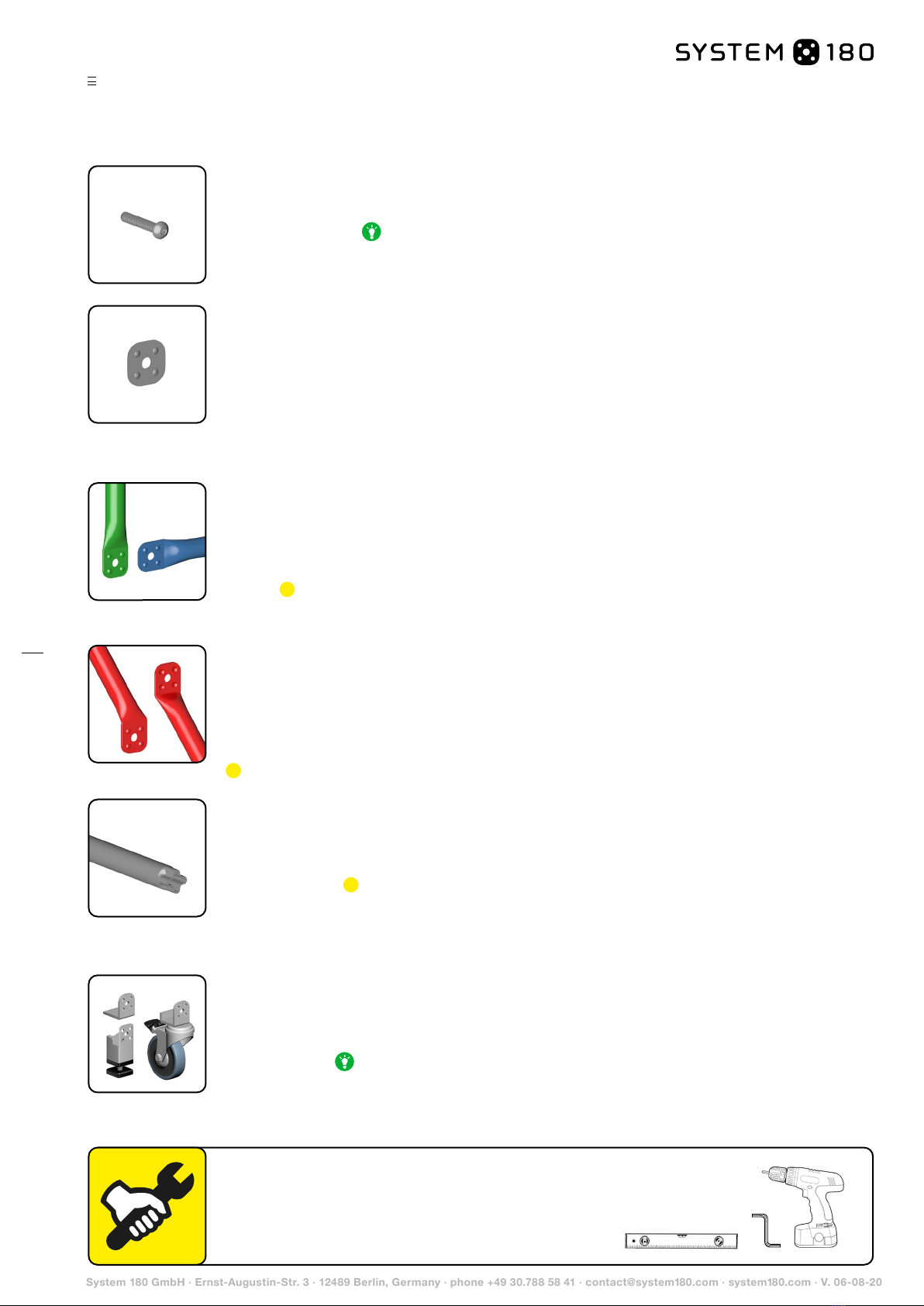
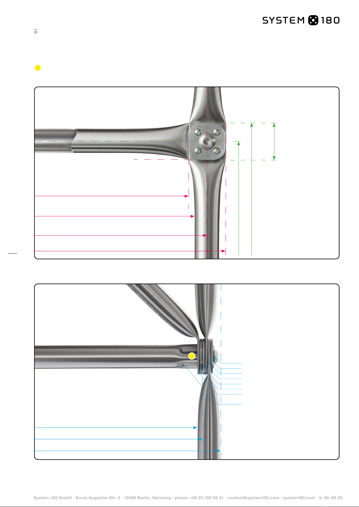
Standard bar (G) Standard bars are stainless steel tubes (20 x 1 mm) with flat-pressed ends and a pattern of
nodules embossed them. To help you to see the system size in which a standard bar has been made, it is pro-
vided with a marking consisting of G + the system size (for example: G360, G720, …). The standard bars form
the vertical and horizontal elements of the tube structure. Their length will depend on the height and width of
the module they form part of. The nodules embossed onto all components should always face outwards during
assembly. Note: From a module width of 810, horizontal bars are fitted with a pin to provide support to the
system base panels. Please make sure that you assemble the correct standard bars in the correct positions.
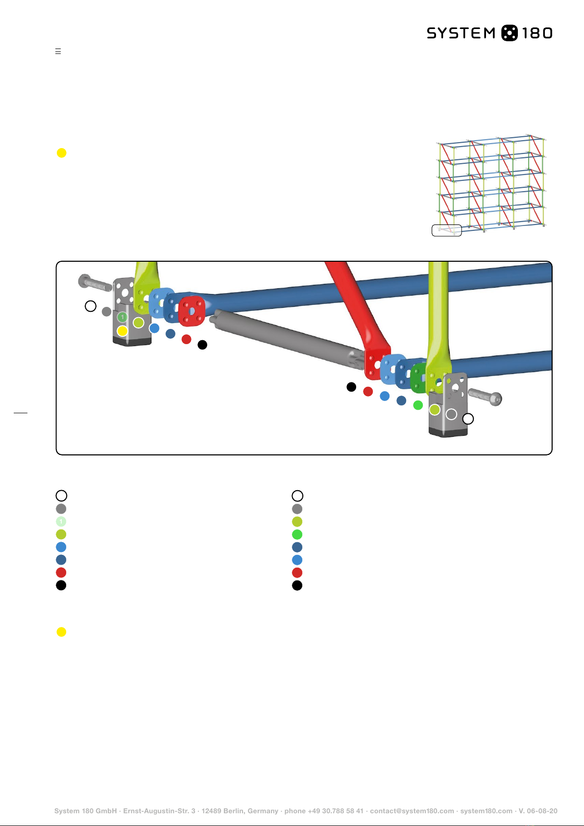
Diagonal bar (D) The system diagonal bar is a stainless steel tube (20 x 1 mm) with flat-pressed, angled
ends, each with embossed nodules facing outwards. The diagonal pieces are designed to provide stiffening
to the tubular structure where no side pieces are included in the module. The length of diagonal bars will vary
according to the height and depth of the module. There is a diagonal piece available for every system height
and depth in the range. The diagonal pieces are always positioned in system nodes directly adjacent to the
connecting bar. The nodules embossed onto all components should always face outwards during assembly.
Note: Diagonal bars are not required where side panels are used.
System washers System washers are steel washers (measuring 30 x 30 x 2 mm), each embossed with 4
nodules and a central hole (ø 8.5 mm). They are designed to provide a termination piece and compensating
element for each system node. On outermost nodes on a module they replace the standard pieces that
would otherwise be there. Where side panels are used, they are placed in the position where the diagonal
pieces would otherwise be placed. They are important in ensuring that the distance between all standard
bars is equal. The system washer is always positioned on the outermost position of its node. (Exceptions: feet
and casters). The nodules always face outwards during assembly. If the nodules are all aligned correctly, then all
components will automatically sit in the nodes at right angles to one another.
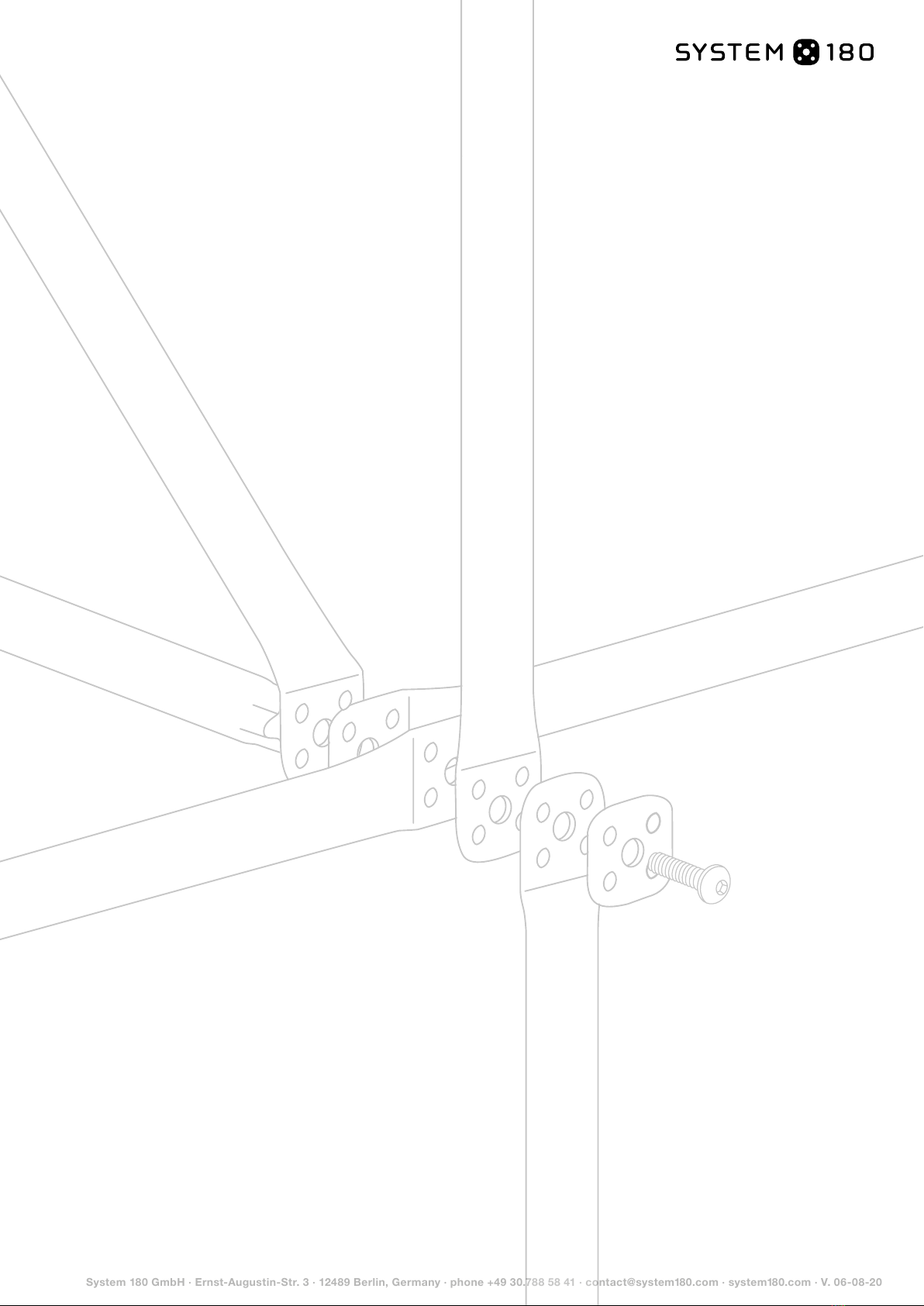
System bolts System bolts are button-headed cylindrical M8x50 bolts with 5-mm hex sockets. System bolts
are pushed through all the elements in each system node back to the connecting bar. As the bolt is tightened
up, the embossed nodules on each component are pressed together into one another, resulting in a structure
locked firmly into place. Tip: During assembly tighten each node up just enough so that the nodules grip
into one another. This will make assembly much easier and is important for when the time comes to insert the
system base components and any panelling.
Foot bases with level adjustment/foot brackets/casters Feet and casters are mounted on the out-
ward-most position of the node. The adjustment devices on foot bases are designed to allow the furniture
module to be levelled out using a spirit level and to even out any unevenness on the floor. Before assembly,
twist all height adjustment devices completely into the foot base to give yourself the maximum amount of initial
clearance possible. Tip: To ensure that you will be able to reach into the rearmost adjustment devices on the
module, we recommend adjusting the height of the unit before fully assembling all its components (before inser-
ting the bottom base panel in particular). Angled feet and casters provide no adjustment function to fine-tune
relative heights. On hard floors (on parquet flooring, for example), use felt gliders for this purpose instead.
Connecting bar (M) The connecting bar consists of a stainless steel tube (20 x 1 mm) with a threaded insert
(M8) pressed into it at each end. The connecting bars are used as the counterpieces for the system bolts
to firmly secure each system node together. Connecting bars run perpendicular to the front of the furniture
module, back to the depth the system structure. There is a connecting rod of suitable length available for
every system depth. Note: For all module depths of 780 and upwards, connecting bars are fitted with a
pin to provide support to the system bases. Please make sure that you assemble the right connecting bars in
the right positions. To ensure the result looks as it should, make sure while assembling that both ends of the
connecting rod look like a vertical "+" sign when looked at end on.
1.1.2 Parts
!
!
!
To assemble the skeletal structure you will need the following tools:
∙ 5 mm hex (Allen) key or cordless electric screwdriver with
the appropriate screwdriver bit; torque: approx. 7 Nm
∙ Spirit level
1.1 Basic structure
This manual suits for next models
5
Table of contents
Popular Indoor Furnishing manuals by other brands

Regency
Regency LWMS3015 Assembly instructions

Furniture of America
Furniture of America CM7751C Assembly instructions

Safavieh Furniture
Safavieh Furniture Estella CNS5731 manual

PLACES OF STYLE
PLACES OF STYLE Ovalfuss Assembly instruction

Trasman
Trasman 1138 Bo1 Assembly manual

Costway
Costway JV10856 manual