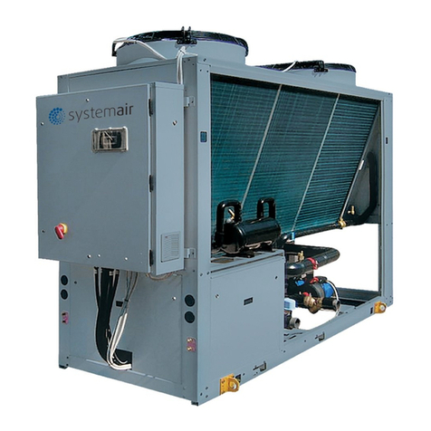
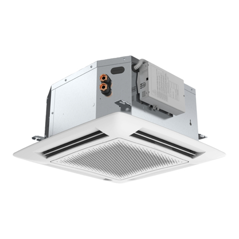
System air SYSAQUA BLUE.L 35B Manual

Installation and maintenance manual
Air Cooled Water Chillers and Heat Pumps
31.7kW
35.4kW
35B
SYSAQUA BLUE


INSTALLATION INSTRUCTION
NOTICE D’INSTALLATION
INSTALLATIONSHANDBUCH
ISTRUZIONI INSTALLAZIONE
INSTRUCCIONES DE INSTALACIÓN
English
Français
Español
Deutsch
Italiano

English
2SYSAQUA BLUE
CONTENTS
1. GENERAL RECOMMENDATIONS........................................................................................................................................................ 3
1.1. SAFETY DIRECTIONS ...................................................................................................................................................................................................................................................................3
1.2. WARNING .....................................................................................................................................................................................................................................................................................3
1.3. EQUIPMENT SAFETY DATA.........................................................................................................................................................................................................................................................4
2. INSPECTION AND STORAGE.............................................................................................................................................................. 5
3. WARRANTY...................................................................................................................................................................................... 5
4. PRESENTATION................................................................................................................................................................................. 5
5. CONTENTS OF PACKAGE ................................................................................................................................................................... 6
5.1. OPTIONAL ACCESSORIES............................................................................................................................................................................................................................................................6
6. DIMENSIONS .................................................................................................................................................................................... 6
7. HANDLING........................................................................................................................................................................................ 6
7.1. NET WEIGHT.................................................................................................................................................................................................................................................................................6
7.2. GRAVITY CENTER POSITION.......................................................................................................................................................................................................................................................6
7.2.1. WITHOUT BUFFER TANK............................................................................................................................................................................................................................................6
7.2.2. WITH BUFFER TANK ...................................................................................................................................................................................................................................................6
7.3. GENERAL HANDLING..................................................................................................................................................................................................................................................................6
7.3.1. HANDLING WITH A FORKLIFT ...................................................................................................................................................................................................................................7
7.3.2. HANDLING BY SLINGING...........................................................................................................................................................................................................................................7
8. TECHNICAL SPECIFICATIONS ............................................................................................................................................................. 8
8.1. PHYSICAL CHARACTERISTICS.....................................................................................................................................................................................................................................................8
8.2. REFRIGERATION SPECIFICATIONS .............................................................................................................................................................................................................................................9
8.2.1. REFRIGERANT CIRCUIT DIAGRAM ............................................................................................................................................................................................................................9
8.2.2. REFRIGERANT CHARGE..............................................................................................................................................................................................................................................9
8.3. ELECTRIC SPECIFICATIONS..........................................................................................................................................................................................................................................................9
8.3.1. SYSAQUA BLUE WITH STANDARD FAN...................................................................................................................................................................................................................9
8.3.2. SYSAQUA BLUE WITH HIGH-PRESSURE FAN..........................................................................................................................................................................................................9
8.4. OPERATING LIMITS................................................................................................................................................................................................................................................................... 10
8.4.1. SYSAQUA BLUE.L/SYSAQUA BLUE.H COOLING MODE...................................................................................................................................................................................... 10
8.4.2. SYSAQUA BLUE.H HEATING MODE....................................................................................................................................................................................................................... 10
9. INSTALLATION ................................................................................................................................................................................ 11
9.1. SITING THE INSTALLATION...................................................................................................................................................................................................................................................... 11
9.1.1. PREVAILING WIND................................................................................................................................................................................................................................................... 11
9.1.2. CONDENSATE WATER MANAGEMENT IN HEATING MODE................................................................................................................................................................................ 11
9.1.3. REDUCING NOISE POLLUTION ............................................................................................................................................................................................................................... 11
9.2. CLEARANCE............................................................................................................................................................................................................................................................................... 12
9.3. ANCHORING TO THE GROUND................................................................................................................................................................................................................................................ 12
10. HYDRAULIC LINKS........................................................................................................................................................................ 13
10.1. MAIN HYDRAULIC CIRCUIT ................................................................................................................................................................................................................................................... 13
10.2. ANTI-CLOGGING PROTECTION ............................................................................................................................................................................................................................................. 13
10.3. MINIMUM WATER VOLUME REQUIREMENTS..................................................................................................................................................................................................................... 14
10.3.1. SYSAQUA BLUE COOLING ONLY VERSION......................................................................................................................................................................................................... 14
10.3.2. SYSAQUA BLUE HEAT PUMP VERSION............................................................................................................................................................................................................... 14
10.4. MAXIMUM WATER VOLUME REQUIREMENTS ................................................................................................................................................................................................................... 14
10.5. RINSING THE CIRCUIT ............................................................................................................................................................................................................................................................ 14
10.6. FROST PROTECTION .............................................................................................................................................................................................................................................................. 15
10.7. WATER QUALITY..................................................................................................................................................................................................................................................................... 16
10.8. HEAT INSULATION.................................................................................................................................................................................................................................................................. 17
10.9. FILLING THE SYSTEM WITH WATER..................................................................................................................................................................................................................................... 17
11. WIRING DIAGRAM AND SETTING RANGE..................................................................................................................................... 18
11.1. WIRING DIAGRAM.................................................................................................................................................................................................................................................................. 18
11.1.1. POWER SUPPLY..................................................................................................................................................................................................................................................... 18
11.1.2. WIRING DIAGRAM KEY DESCRIPTIONS.............................................................................................................................................................................................................. 18
11.2. RANGE AND SETTINGS OF THEMAL PROTECTION............................................................................................................................................................................................................ 18
11.3. GAS DETECTION CARD CONTROL RANGE.......................................................................................................................................................................................................................... 18
12. ELECTRICAL CONNECTIONS........................................................................................................................................................... 19
12.1. UNIT POWER SUPPLY............................................................................................................................................................................................................................................................. 20
12.2. ALARM INDICATORS.............................................................................................................................................................................................................................................................. 21
12.2.1. MAIN CONTROLLER.............................................................................................................................................................................................................................................. 21
12.2.2. GAS DETECTION MODULE.................................................................................................................................................................................................................................... 21
12.3. ALL SEASONS AND VARIABLE FLOW PUMP OPTIONS ..................................................................................................................................................................................................... 21
13. CONTROL...................................................................................................................................................................................... 22
13.1. ORDER OF PRIORITY FOR CONTROL SYSTEMS.................................................................................................................................................................................................................. 22
13.2. USER INTERFACE.................................................................................................................................................................................................................................................................... 22
13.2.1. KEYPAD................................................................................................................................................................................................................................................................... 22
13.2.2. HOME PAGE ........................................................................................................................................................................................................................................................... 23
13.2.3. MAIN MENU .......................................................................................................................................................................................................................................................... 23
13.2.4. MENUS.................................................................................................................................................................................................................................................................... 23
13.3. INITIAL SETTINGS................................................................................................................................................................................................................................................................... 24
13.3.1. TIME SETTINGS...................................................................................................................................................................................................................................................... 24
13.3.2. LANGUAGE SETTINGS...........................................................................................................................................................................................................................................24
13.3.3. DEFINING THE GLYCOL RATE ............................................................................................................................................................................................................................... 25
13.4. LAUNCHING THE SYSAQUA BLUE SYSTEM ........................................................................................................................................................................................................................ 25
13.4.1. CONFIGURING INPUT D1...................................................................................................................................................................................................................................... 25
13.4.2. CONFIGURING INPUT D2...................................................................................................................................................................................................................................... 26
13.4.3. HEAT/COOL SELECTION........................................................................................................................................................................................................................................ 26
13.4.4. SELECTING THE OPERATING MODE.................................................................................................................................................................................................................... 27
13.4.5. USER TEMPERATURE SETPOINTS AND ACTUAL SETPOINTS........................................................................................................................................................................... 27
13.4.6. WATER LAW........................................................................................................................................................................................................................................................... 28
13.4.7. "VARIABLE PRIMARY FLOW” OPTION ............................................................................................................................................................................................................... 30
13.4.8. REDUCED MODE.................................................................................................................................................................................................................................................... 33
13.4.9. LIMITED CAPACITY................................................................................................................................................................................................................................................ 33
13.5. ALARMS .................................................................................................................................................................................................................................................................................. 34
13.5.1. ALARM DETAILS.................................................................................................................................................................................................................................................... 34
13.5.2. THE LIST OF ACTIVE ALARMS.............................................................................................................................................................................................................................. 34
13.5.3. ALARMS HISTORY................................................................................................................................................................................................................................................. 35
13.6. SCHEDULE ............................................................................................................................................................................................................................................................................... 35
14. COMMISSIONING.......................................................................................................................................................................... 36
14.1. LIST OF PRELIMINARY CHECKS ............................................................................................................................................................................................................................................ 36
14.1.1. VISUAL CHECK ....................................................................................................................................................................................................................................................... 36
14.1.2. ELECTRICAL CHECK ............................................................................................................................................................................................................................................... 36
14.1.3. HYDRAULIC CHECK................................................................................................................................................................................................................................................ 37
14.1.4. REFRIGERATING CHECKS...................................................................................................................................................................................................................................... 37
14.2. UNIT START-UP....................................................................................................................................................................................................................................................................... 37
14.3. OPERATING CHECK LIST........................................................................................................................................................................................................................................................ 37
14.3.1. GENERAL................................................................................................................................................................................................................................................................ 37
14.3.2. PHASE ROTATION PROTECTION .......................................................................................................................................................................................................................... 37
14.3.3. ELECTRICAL............................................................................................................................................................................................................................................................ 37
14.3.4. HYDRAULIC CIRCUIT.............................................................................................................................................................................................................................................. 38
14.3.5. COMPRESSOR AND REFRIGERATION SYSTEM.................................................................................................................................................................................................. 38
14.3.6. FINAL CHECK.......................................................................................................................................................................................................................................................... 38
15. WARRANTY CLAIM - MATERIAL RETURN PROCEDURE................................................................................................................. 38
16. ORDERING SERVICE AND SPARE PARTS ORDER ........................................................................................................................... 39
17. MAINTENANCE............................................................................................................................................................................. 39
17.1. WEEKLY CHECK....................................................................................................................................................................................................................................................................... 40
17.2. TABLE OF PERIODIC SERVICE AND MAINTENANCE........................................................................................................................................................................................................... 41
17.3. MAINTENANCE PROCEDURES.............................................................................................................................................................................................................................................. 43
17.3.1. REFRIGERANT CIRCUIT.......................................................................................................................................................................................................................................... 43
17.3.2. HYDRAULIC CIRCUIT.............................................................................................................................................................................................................................................. 44
17.3.3. WINTER PROTECTION .......................................................................................................................................................................................................................................... 44
18. TROUBLESHOOTING...................................................................................................................................................................... 45
English
3SYSAQUA BLUE
1. GENERAL RECOMMENDATIONS
POWER SUPPLY MUST BE
SWITCHED OFF BEFORE STARTING
WORK IN THE ELECTRIC CONTROL
BOX
The purpose of this Manual is to provide users with instructions for installing, commissioning, using and
maintaining the units. It also contains instructions on starting up the machine as well as recommendations
to avoid bodily injury and risks of damage to the device during its operation.
It does not contain the complete description of all the maintenance operations guaranteeing the unit’s long
life and reliability. Only the services of a qualied technician can guarantee the unit’s safe operation over a
long service life.
Please read the following safety precautions very carefully before installing the unit.
1.1. SAFETY DIRECTIONS
Cut off the power supply before starting work on the appliance.
When forming the hydraulic connections, ensure that no impurities are introduced into the pipe work.
The manufacturer declines any responsibility and the warranty becomes void if these instructions are not
complied with.
If you encounter a problem, please call the Technical Department for your area.
If possible, assemble the compulsory or optional accessories before placing the appliance in its nal location
(see instructions provided with each accessory).
To familiarize yourself fully with the appliance, we recommend that you also read our Technical Instructions.
The information contained in these Instructions is subject to modication without advance notice.
1.2. WARNING
Follow the safety rules in force when you are working on your appliance.
The installation, commissioning, use and maintenance of these units should be performed by qualied
personnel who have a good knowledge of standards and local regulations, as well as experience of this
type of equipment.
This appliance has not been designed for use by persons (including children) with reduced physical, sensorial
or mental faculties or by persons without any experience or knowledge of heating systems, unless they act
under the safety and supervision of a responsible person or have received prior training concerning the use
of the appliance.
The unit should be handled using lifting and handling equipment appropriate to the unit's size and weight.
Any wiring produced on site must comply with the corresponding national electrical regulations.
Make sure that the power supply and its frequency are adapted to the required electric current of operation,
taking into account specic conditions of the location and the current required for any other appliance
connected to the same circuit.
The unit must be EARTHED to avoid any risks caused by insulation defects.
Work must not be carried out on the electrical components if water or high humidity is present at the
installation site.
SAFETY SYMBOLS
ELECTRIC
VOLTAGE
ROTATING PART RISK OF
ASPHYXIA
PRESSURIZED
EQUIPMENT
FLAMMABLE
GAS
RISK OF
CUTTING
RISK OF BURNS

English
4SYSAQUA BLUE
1.3. EQUIPMENT SAFETY DATA
Safety data R290
Toxicity level Acute toxicity
In contact with the skin
If the fluid comes into contact with your skin:
treat the freeze burns as you would a normal burn. Immediately remove all contaminated clothing
and footwear
Rinse the affected area immediately with plenty of water
If you burn your skin, call a doctor without delay.
In case of eye contact Hold the eyelids open and flush immediately with water for at least 15 minutes.
Consult an ophthalmologist without delay, even if there are no immediate visible signs of damage.
Ingestion Not specifically concerned (gas)
Inhalation If inhaled, move to fresh air and give oxygen if necessary. Perform artificial respiration if the patient
is no longer breathing or is short of air. In the event of cardiac arrest, perform external CPR. Seek
immediate medical attention.
Acute symptoms
Coma
Convulsions
Depression of the central nervous system
Headaches
Nausea
Cardiac disease
Vomiting
Occupational exposure limits 1000 ppm - 8 hours
1800 mg/m3- 8 hours 4000 ppm - 15 minutes
7200 mg/m3- 15 minutes
Stability Stable at ambient temperature and in normal conditions of use
Incompatible materials Strong bases
Powerful oxidants
Oxidizing materials
General precautions
Avoid inhaling high concentrations of vapors. Atmospheric concentrations should be minimized
and kept as far as possible below the occupational exposure limit. Steam is heavier than air and
concentrates at a low level and in small places. Exhaust ventilation at the lowest levels.
Distance ignition possible
Risk of explosion if heated in a confined environment
Respiratory protection AX-type rubber mask
In the event of inadequate ventilation, insulating self-contained breathing apparatus
Storage and handling
The tanks must be located in a dry and cold room that is fireproof, protected from direct sunlight and
away from all sources of heat, e.g. radiators. Storage rooms must be well ventilated.
When handling, it is necessary to:
perform operations with apparatus and equipment designed for use in an explosive atmosphere.
prevent the build-up of electrostatic charges. refrain from smoking.
work in a well-ventilated room.
Protective clothing Anti-static gloves
Safety glasses with side shields
Anti-static clothing
Procedure in case of spillage or
a leak
Evacuate the hazardous area
Only qualified personnel wearing the appropriate protective equipment must perform handling
operations.
Eliminate all sources of ignition if you can safely do so.
Prevent the product from penetrating wine cellars, basements, work trenches, etc.
Prevent the product from entering the sewers (explosion risk)
Mechanically ventilate the spill area
Use water spray to disperse vapors
Ignited gas leak: Do not switch off if the leak cannot be stopped without risk
Waste disposal Dispose of waste at a specialist waste center
Fire fighting data
Keep away from heat / sparks / naked flames / hot surfaces. - Refrain from smoking.
Suitable extinguishing agents:
Small fire: Carbon dioxide (CO2), powders
Large fire: Sprinkler
Fire protection equipment In case of fire, wear self-contained breathing apparatus and protective clothing.

English
5SYSAQUA BLUE
2. INSPECTION AND STORAGE
Upon receipt of the equipment, carefully cross check all the elements against the shipping documents to
ensure that all expected crates and boxes have been delivered. Inspect all the units for any visible or hidden
damage.
In the event of shipping damage, write precise details of the damage on the shipper’s delivery note and
send a registered letter to the shipper within 48 hours, clearly stating the damage caused. Forward a
copy of this letter to the manufacturer or the latter's representative.
Never store or transport the unit upside down. It must be stored indoors, completely protected from rain,
snow etc. The unit must not be damaged by changes in the weather (high and low temperatures). Excessively
high temperatures (above 60°C) can harm certain plastic materials and cause permanent damage. Moreover,
the performance of certain electrical or electronic components can be impaired.
The appliances are delivered fully assembled, factory tested and ready to operate.
Any modication to the units without the manufacturer’s prior approval, shall automatically render the
warranty null and void.
The following conditions must be respected in order to maintain the validity of the warranty:
²Commissioning shall be performed by specialized technicians from technical services approved by
the manufacturer.
²Maintenance shall be performed by trained maintenance technicians.
²Only Original Equipment spare parts shall be used.
²All the operations listed in the present manual shall be performed within the required time limits.
THE WARRANTY SHALL BE NULL AND VOID IN THE EVENT
OF NON-COMPLIANCE WITH ANY OF THE ABOVE CONDITIONS.
3. WARRANTY
All the models in the SYSAQUA BLUE liquid coolers range are produced in compliance with state-of-the-
art design and manufacturing standards. This guarantees their high performance and reliability as well
as their compatibility with all types of air conditioning installations operating with both chilled water and
glycol solutions (and with hot water for the Heat pump units). The unit, designed for an outdoor mounted
application, is not suitable for any uses other than those specied in this manual.
Improper usage of the unit or a use for purposes other than those originally intended, without the prior
approval of the manufacturer or the latter's agents, could result in the unit functioning outside its safe
operating limits and could present risks to both personnel and property.
4. PRESENTATION
The Cooling only models can produce chilled water at temperatures varying from +18°C to +5°C or chilled
water/glycol solution at temperatures varying from +5°C to -15°C.
The Heat pump models can produce hot water at temperatures varying from +20°C to +60°C.
SYSAQUA BLUE are packaged units, optimized for air conditioning applications.
Following assembly of the units:
1. the electrical circuits are tested.
2. refrigeration circuits receive their operational refrigerant charge and are subject to pressurized leak
detection tests.
3. The SYSAQUA BLUE units are tested.
These tests are conducted to guarantee the correct operation and quality of our products.

English
X
Y
Z
0
X
Y
Z
0
6SYSAQUA BLUE
SEE APPENDIX
5. CONTENTS OF PACKAGE
On opening the box, check that all of the accessories required for installation are present.
5.1. OPTIONAL ACCESSORIES
Anti-vibration rubber pads
Spring pads
Isolating valve
1 SYSAQUA BLUE
1 Water lter
1 Bag with the documentation
6. DIMENSIONS
7. HANDLING
7.1. NET WEIGHT
7.2. GRAVITY CENTER POSITION
The handling method depends on the SYSAQUA BLUE model and its nal destination.
²Take care to avoid any rough handling or impacts when unloading and moving the appliance.
²Before hoisting the appliance into position, perform a test lift to ensure stability and balance. Avoid
twisting or uneven lifting of the units.
²The units shall be carefully inspected before unit installation to make sure this has not happened.
²All of these sections are inspected before they leave the factory. Prior to commissioning, it is
therefore important to make sure that no bolts, screws or other fastening components are loosened
or missing.
35B
Without pump kg 307
1 pump kg 20
2 pumps kg /
XLN kg /
Buffer tank Kg 65
To avoid irreversible damage, do not tilt the SYSAQUA BLUE by more than 45° during handling.
Caution
Never move the SYSAQUA BLUE on rollers.
Caution
Never subject the metal work (panels, posts) of the SYSAQUA BLUE to handling constraints, as only
its base is designed for that purpose.
Caution
35B
XGmm 496
YGmm 498
ZGmm 695
35B
XGmm 593
YGmm 681
ZGmm 548
7.2.1. WITHOUT BUFFER TANK
7.2.2. WITH BUFFER TANK
7.3. GENERAL HANDLING

English
7SYSAQUA BLUE
7.3.1. HANDLING WITH A FORKLIFT
A forklift can be used to handle the SYSAQUA BLUE units when palletized.
Place a safety wedge between the unit base and the fork lift truck to avoid damaging the unit’s structure
and casing.
7.3.2. HANDLING BY SLINGING
Lifting is also possible by slinging.
Holes are made at each end of the unit to allow the insertion of slinging bars along the chassis width.
A spreader must be used to prevent damage to the machine edges.
35B
Hole diameter mm 30
When handling the SYSAQUA BLUE, beware not to damage the nned battery pack. Protect it with
cardboard or particle panels.
Caution
Slings must never touch the casing of the SYSAQUA BLUE unit.
Caution
SYSAQUA BLUE 35B SYSAQUA BLUE 35B
WITH BUFFER TANK

English
8SYSAQUA BLUE
8. TECHNICAL SPECIFICATIONS
8.1. PHYSICAL CHARACTERISTICS
(1) according to Eurovent.
35B
Supply voltage 400V / 3~ N / 50Hz
Number of refrigeration circuits 1
REFRIGERANT
Type R290
Factory charge SEE NAME PLATE
COMPRESSORS
Type Scroll
Number 2
Startup type DIRECT
Part load steps % 0/50/100
Crankcase heater W 2x53
EVAPORATOR
Type plates
Number 1
Water volume L3:32
Cooling Only water ow
nominal
m3/hr
5:40
minimum 3:40
maximum 9:02
Water pressure losses kPa 18
Heat
Pump
Cooling
mode
water ow
nominal
m3/hr
5:40
minimum 3:40
maximum 9:02
Water pressure losses kPa 18
Heating
mode
water ow
nominal
m3/hr
6:10
minimum 3.84
maximum 10:19
Water pressure losses kPa 23
Antifreeze electric heater W 30
FANS
Type AXIAL
Number 1
STD
Speed rpm 675
Air ow rate m3/hr 15,840
Input power W 695
HPF
Speed rpm 874
Air ow rate m3/hr 15,840
Input power W 1,922
Static Pressure Pa 170
COILS
Number 1
Frontal surface m² 2.79
Number of rows 2
HYDRAULIC LINKS
Type Male gas threaded
Inlet diameter inches 1" 1/2
Outlet diameter inches 1" 1/2
BUFFER TANK (OPTION)
Volume L 100
ACOUSTIC DATA
Sound power level (1)
STD dB(A) 83
HPF dB(A) 84
XLN dB(A) /

English
9SYSAQUA BLUE
8.2. REFRIGERATION SPECIFICATIONS
8.2.1. REFRIGERANT CIRCUIT DIAGRAM
SEE APPENDIX
8.2.2. REFRIGERANT CHARGE
The type and quantity of refrigerant per circuit is indicated on the product plate.
SYSAQUA BLUE units use R290 refrigerant, which is a group 2 refrigerant as dened in directive
2014/68/EU. Considering the maximum operating pressure of these units (27.2 bar(g)), they
integrate category 2 (or lower) components as dened in directive 2014/68/EU. In compliance with
Directive PED 2014/68/EU and harmonized standard EN378 (1 to 4), these SYSAQUA BLUE units are
classed as category 2.
Caution
8.3. ELECTRIC SPECIFICATIONS
8.3.1. SYSAQUA BLUE WITH STANDARD FAN
35B
Power supply 400V / 3~ N / 50Hz
Without
pump
Maximum current A 34.0
Total starting current (without soft starter) A 120.0
Total starting current (with soft starter) A 54.6
With
pump
Maximum current A 37.0
Total starting current (without soft starter) A 123.0
Total starting current (with soft starter) A 57.6
IMPORTANT
* This data is given for guidance only. It must be checked and adjusted in accordance with prevailing
standards. It depends on the installation and the cables used.
A main fuse must be provided on the power supply.
²Fuses not supplied
²Cables not supplied
35B
Power supply 400V / 3~ N / 50Hz
Without
pump
Maximum current A 36.0
Total starting current (without soft starter) A 122.0
Total starting current (with soft starter) A 56.6
With
pump
Maximum current A 39.0
Total starting current (without soft starter) A 125.0
Total starting current (with soft starter) A 59.6
8.3.2. SYSAQUA BLUE WITH HIGH-PRESSURE FAN
This equipment contains a hydrocarbon (R290) that belongs to uid category I as per standard
EN378‑1. Unlike uorocarbon uids, this gas presents no risk to the environment (low GWP, uid
not covered by the Kyoto Protocol).
Caution
However, this is an A3 category ammable uid with a consequent risk of re or explosion (EN1127‑1). It
must be handled by skilled personnel who are trained in the use of ammable refrigerants. The installer
and the end user must know the local regulations governing the installation, operation and disposal of the
equipment, in particular with regards to the retrieval of substances presenting a risk of re or explosion.

English
-20
-15
-10
-5
0
5
10
15
20
25
30
35
40
45
50
55
-20 -15 -10 -5 0 5 10 15
20
Leaving water temperature (°C)
BRINES or
WATER + GLYCOL
+ Fan speed controller
WATER + Fan
speed controller
BRINES or
WATER + GLYCOL WATER
OAT - Outdoor air temperature (°C)
-25
-20
-15
-10
-5
0
5
10
15
20
25
15 20 25 30 35 40 45 50 55 60
65
Leaving water temperature (°C)
OAT - Outdoor air temperature (°C)
10 SYSAQUA BLUE
8.4. OPERATING LIMITS
8.4.1. SYSAQUA BLUE.L/SYSAQUA BLUE.H COOLING MODE
8.4.2. SYSAQUA BLUE.H HEATING MODE

English
11SYSAQUA BLUE
9. INSTALLATION
9.1. SITING THE INSTALLATION
The SYSAQUA BLUE must be installed outdoors with sufcient surrounding clearance to enable air to circulate
freely through the appliance and to allow access for maintenance work.
In the case of the unit being sited in areas exposed to high winds, you must avoid the wind hitting the fan
blowing surface areas directly to avoid any risk of recycling cooled air at the nned battery. Exchanger fan
operation can be disrupted by strong winds, which can cause de-icing problems and fan malfunctions.
Depending on outdoor temperature and air humidity conditions, water vapor contained in the air can
condense on the nned heat exchanger and even form ice at low outdoor temperatures (around < 5°C).
This condensate water and defrosted water runs off via outlets provided under the exchanger. To aid water
run-off and avoid frozen water remaining in the appliance in winter, we recommend that it is mounted at a
height of around 10cm off the ground. This will allow the water to run off freely and be absorbed into the
ground or channeled to a basin built under the appliance in order to protect the environment.
In areas where outdoor temperatures drop below 1°C, the system can be equipped with a condensate anti-
freeze protection system (e.g. a heated pipe sheath, optionally available).
In orderto contain noise levels,we equip our applianceswith quiet fans and encase the technical compartment
in sound-proofed panels. However, noise levels can be reduced even further by taking a few installation
precautions:
²Do not install the appliance near a window.
²Do not install the unit in enclosed or conned yards, narrow locations where noise may bounce off
walls.
²Install the rubber pads supplied or anti-vibration pads (available as an option) under the appliance.
²Do not join the concrete slab supporting the appliance to the building structure (structure-borne
noise transmission).
²Electrical and hydraulic connections to the unit must be exible to avoid the transmission of
vibrations.
9.1.1. PREVAILING WIND
9.1.2. CONDENSATE WATER MANAGEMENT IN HEATING MODE
9.1.3. REDUCING NOISE POLLUTION
The unit is not designed to withstand weights or stresses from adjacent equipment, pipe work
or constructions. Any foreign weight or stress on the unit structure could lead to a malfunction or
damage, which could prove hazardous to personnel and property. In such an event, the warranty
shall be voided.
Caution
The unit base shall be arranged as indicated in the manual. There could be a risk of personal injury
or damage to property in the event of the unit being incorrectly supported.
Caution
Unit operation depends on air temperature. Any recycling of air extracted by the fan lowers the air
intake temperature across the exchanger ns and alters the standard operating conditions.
Caution
Do not expose the SYSAQUA BLUE to rejections from chimneys or vents. Fumes charged with soot
or grease as well as acid rejections are likely to permanently clog or damage the condenser. This
would void the warranty.
Caution
As per standard EN378-1 §5.1, the SYSAQUA BLUE unit is a category A installation in terms of access and a
class III installation in terms of location.

English
2 000
2 000
3 000
2 000
2 000
911
1 050
2 000
2 000
3 000
2 000
2 000
1 418
1 050
12 SYSAQUA BLUE
9.2. CLEARANCE
9.3. ANCHORING TO THE GROUND
The surface of the oor or structure located under the SYSAQUA BLUE must be at, and strong enough to
withstand the unit's weight with its full liquid load, in addition to the occasional presence of maintenance
equipment.
For normal applications, rigidity of the SYSAQUA BLUE and the positions of the supports allow for an
installation that minimizes vibrations. However, the installers can use anti-vibration rubber pads (supplied
as an option).
The SYSAQUA BLUE only needs to be anchored to the foundations in regions exposed to a high earthquake
risk or if the appliance is installed at a high level on a steel frame.
When tting anti‑vibration pads, refer to the manual supplied with the kit.
When several SYSAQUA BLUE units are installed, ensure proper clearance is implemented around the
condensers specic to each machine.
Caution
SYSAQUA BLUE 35B SYSAQUA BLUE 35B
WITH BUFFER TANK
The unit is equipped with a R290 refrigerant leak
detection card enabling it to be shut down and for
the hydrocarbon to be expelled into the atmosphere
(before reaching the uid ammability limit). To
ensure this, two apertures are present on the frame:
the rst, equipped with an extractor fan, sucks
outside air into the frame and the second expels
waste air into the atmosphere.
These minimum clearance dimensions must be complied with to ensure correct operation of the unit, to
enable the unit to be accessed and maintained, and, above all, to guarantee the safety of personnel.
During installation, it is important to leave sufcient
clearance around the SYSAQUA BLUE.

English
13SYSAQUA BLUE
10. HYDRAULIC LINKS
10.1. MAIN HYDRAULIC CIRCUIT
You must design the pipe network with the minimum number of bends and keep the number of hydraulic
components generating pressure drops to the strict minimum. This will reduce installation costs and ensure
optimum system performance. The pipe network must include:
²A vibration elimination system (e.g.: link hoses) on all pipes connected to the appliance in order to
reduce vibrations and noise transmitted to the building fabric.
²A balancing valve on the water outlet pipe in order to adjust the water ow.
²Stop cocks to isolate the hydraulic circuit during maintenance.
²Manual or automatic bleed valves at the highest point on the water circuit.
²Draining connectors at all low points to allow complete circuit draining.
²A circulation pump guaranteeing ow necessary for the operation of the SYSAQUA BLUE unit.
²A diaphragm expansion tank tted with a safety and draining valve must be visible.
²A low water pressure sensor to secure the water pump against cavitation if the water pressure in the
circuit decreases.
²The installation of thermometers and pressure gages on the heat exchanger inlet and outlet to
facilitate day-to-day controls and system maintenance.
²An element ensuring ground continuity of all piping. An unbalance of grounding connection points
can cause electrolytic corrosion.
10.2. ANTI-CLOGGING PROTECTION
Failure to install a water lter would result in clogging of the SYSAQUABLUE's heat plate exchanger soon after
commissioning. Proper operation of the SYSAQUA
BLUE would be disturbed by a reduced water ow
or the partial clogging of certain heat plates. The
heat plate exchanger could be IRREVERSIBLY
damaged in the event of inadequate water ow.
A mesh size of smaller than or equal to 800µm is
recommended
The mains hydraulic circuit will provide a constant water ow on the refrigerating uid/water plate
exchanger and in case of load variation.
Caution
When choosing and installing water pipes, you must consult and observe all current local standards,
regulations and instructions.
Caution
The expansion tank must be dimensioned to be able to absorb an expansion corresponding to 2%
total volume of water contained in the installation (exchanger, piping, installations and buffer tank,
if present).
Caution
THE WARRANTY DOES NOT COVER DAMAGE DUE TO CORROSION RESULTING FROM ELECTROLYTIC
PHENOMENA.
Caution
To avoid anyrisk of foreign bodies entering the appliance and to guarantee operating performance,
IT IS IMPERATIVE TO INSTALL A WATER FILTER on the SYSAQUA BLUE inlet pipe.
Caution
THE MANUFACTURER'S WARRANTY IS VOID IF THE FILTER SUPPLIED WITH
THE SYSAQUA BLUE IS NOT INSTALLED TO PROTECT THE APPLIANCE
Caution

English
14 SYSAQUA BLUE
Before lling the installation, check it and remove any contamination such as sand, stones, welding
chips and other materials likely to damage the SYSAQUA BLUE.
Caution
For refrigeration only units, the total volume at the primary water circuit must never be below:
²air conditioning application
3.5 L/kW refrigeration power
²process application
10 L/kW refrigeration power
10.3. MINIMUM WATER VOLUME REQUIREMENTS
To ensure that the system operates correctly you must use suitably sized and properly routed pipes for the
hydraulic links between the SYSAQUA BLUE and the mains network. Proper operation of the regulation and
safety devices is ensured only when the water volume is sufcient.
10.3.1. SYSAQUA BLUE COOLING ONLY VERSION
10.3.2. SYSAQUA BLUE HEAT PUMP VERSION
For reversible units, a water volume equal to 12.5 L/kW is recommended, so that energy reserves are full
enough to ensure the defrosting cycle without any discomfort for the end user.
If the total volume of the primary hydraulic circuit does not allow these recommendations to be adhered
to, a buffer tank must be added to the installation to increase the water volume up to the value required.
If the unit runs with a low volume of water (with air treatment plant…) or if it is used for industrial processes,
a buffer tank is compulsory to guarantee sufcient thermal inertia and adequate temperature stability.
10.4. MAXIMUM WATER VOLUME REQUIREMENTS
The maximum water volume is limited by the size of the unit's expansion tank and/or the expansion tank
present in the installation's hydraulic circuit. Expansion tanks must be sized according to the percentage of
glycol in the hydraulic circuit.
Fully rinse all water pipes before nal connection to the SYSAQUA BLUE.
When using an off-the-shelf acid rinsing solution, implement a temporary branching around the SYSAQUA
BLUE to prevent damaging internal components (particularly the plate exchanger, ow switch, pump...).
10.5. RINSING THE CIRCUIT
Optional internal water tank:
²SYSAQUA BLUE 35B 100L
The volume of the expansion tanks selected with single pump and double pump options are:
The expansion tank should be installed at the pump suction, and its pressure will be adjusted by taking into
account the whole hydraulic circuit.
35B
volume of the expansion tank supplied with
hydraulic options L8
35B
Minimum water volume in the air conditioning
application system Without buffer tank L 111
With buffer tank L 11
Minimum water volume in the process
application system Without buffer tank L 317
With buffer tank L 217
35B
Minimum water volume in the system Without buffer tank L 443
With buffer tank L 343

English
15SYSAQUA BLUE
For heatpump models, if the outdoor temperature is likely to fall below +1°C, provide a system to
prevent the condensates from freezing (e.g. heating cord).
Caution
THE USE OF A GLYCOL-BASED SOLUTION IS THE ONLY EFFECTIVE FROST-PROTECTION MEANS
Caution
Never ll the hydraulic circuit with pure glycol. Maximum glycol concentration is 45%. The water
and glycol mixture must be precisely prepared before lling the hydraulic circuit. If the mixture is too
concentrated, the hydraulic circuit could be damaged and the SYSAQUA BLUE unit will not perform
normally. In this case, the unit warranty will be automatically voided.
Caution
The percentage of glycol in the installation's hydraulic circuit must be entered in the regulation
upon start-up. This parameter setting changes the safety and alarm triggering threshold limits. An
incorrect value may cause malfunctions and destruction of the unit's heat exchanger.
Caution
10.6. FROST PROTECTION
If the SYSAQUA BLUE is exposed to ambient temperatures between 1°C and -18°C, protect the water circuit
against frost.
Draining the water circuit is not recommended for frost protection, for the following reasons:
²The water circuit will rust, which will shorten its service life.
²Water will remain at the bottom of the plate exchangers and freezing may cause damage.
The glycol‑based water solution must be sufciently concentrated to ensure appropriate protection and
prevent ice from forming at the minimum outdoor temperatures planned for the installation. Take precautions
when using non inert MEG antifreeze solutions (Mono Ethylene Glycol or MPG Mono Propylene Glycol). With
this type of antifreeze solution, corrosion may occur in the presence of oxygen.
Contact glycol resellers to ensure that its characteristics are compatible with the environmental directive
applicable on site (this is not the manufacturer's responsibility).
The glycol‑based solution slightly modies the installation's performance, particularly in terms of load loss:
Minimum outdoor temp. °C 5 > T > 0 0 > T > -5 -5 > T > -10 -10 > T > -30
Mono Ethylene Glycol concentration % 10 20 30 45
Correction
factor
load loss 1.070 1.160 1.235 1.368
water ow 1.015 1.050 1.085 1.169
thermodynamic power 0.995 0.985 0.970 0.949
Example for a solution with 20% Mono Ethylene Glycol:
²Increase the pressure drop: with glycol = 1.160 x without glycol
²Increase the owrate: with glycol = 1.050 x without glycol
²Decrease the capacity: with glycol = 0.985 x without glycol
Minimum outdoor temp. °C 5 > T > 0 0 > T > -5 -5 > T > -10 -10 > T > -27
Mono Propylene Glycol concentration % 10 20 30 45
Correction
factor
load loss 1.112 1.175 1.290 1.520
water ow 1.005 1.030 1.067 1.162
thermodynamic power 0.991 0.977 0.945 0.894
Warning
It is advisable to clearly record the type of glycol used, as well as the glycol concentration, on the
electric cabinet.

English
16 SYSAQUA BLUE
10.7. WATER QUALITY
The water must be analyzed; the hydraulic network system installed must include all elements necessary
for water treatment: lters, additives, intermediate exchangers, drain valves, vents, check valves, etc.,
according to the results of the analysis.
Using improperly treated or untreated water in the SYSAQUA BLUE may cause scaling, erosion, corrosion or
algae or sludge deposits in the exchangers. Refer to a water treatment expert to determine any treatment
required. The manufacturer will not be held liable for damage caused when untreated or improperly treated
water, demineralized water, salt water or seawater are used.
Apply the following guidelines:
²No NH4+ ammonium ions in the water, highly detrimental to copper. <10mg/l
²Cl‑ chloride ions are detrimental to copper with a risk of puncture by pitting. <10mg/l.
²SO42- sulphate ions may cause pitting corrosion. < 30mg/l.
²No uoride ions (<0.1 mg/l)
²No Fe2+ and Fe3+ ions, particularly in the case of dissolved oxygen. Fe< 5mg/l with dissolved oxygen
< 5mg/l. The presence of these ions with dissolved oxygen indicates corrosion of steel parts, likely
to generate corrosion of copper parts under Fe deposits, particularly in the case of multitubular
exchangers.
²Dissolved silica: silica is an acid element of water and may also cause corrosion. Content < 1mg/l.
²Water hardness: Values between 10°fH and 30°fH may be recommended. This facilitates scaling
deposits likely to limit copper corrosion. Excess TH values may lead to clogging of the pipes.
²TAC<100
²Dissolved oxygen: Prevent any sudden change in the water's oxygenation conditions. Also, avoid
deoxygenating water by sparging inert gas as well as overoxygenating it by sparging pure oxygen.
Disturbing oxygenation conditions destabilizes copper hydroxides and particle salting-out.
²Electrical Resistivity - Conductivity: The higher the resistivity, the slower the corrosion. Values
above 3000 ohm/cm are preferred. A neutral environment favors maximum resistivity. For electrical
conductivity, values around 200-600 S/cm can be recommended.
²pH: neutral pH at 20°C (7 < pH < 9)
The SYSAQUA BLUE must not run on a network with open loops, likely to cause incidents related
to oxygenation, or with untreated ground water.
Caution
If the water circuit is to be drained for a period of longer than one month, the circuit must be fully
charged with nitrogen to prevent any risk of corrosion by differential venting.
Caution
The manufacturer is not liable for recommendations regarding water treatment (call a specialized
company).
However, this matter has a critical nature, and particular care must be taken to ensure that the type
of treatment applied is effective.
The manufacturer or the latter's representative will not be held liable when untreated water or
non-compliant quality water is used.
Caution

English
VV VR
VV VR
UNIT 1
UNIT 2
V : Isolating valves VR : Balancing valves
17SYSAQUA BLUE
When two or three units are connected in parallel, it is advisable to reverse the return circuit connections
(Tichcelmann loop) in order to reduce the pressure loss in each unit’s circuit.
Always check that manual or automatic air drains are installed at all the high points of the hydraulic network.
Install a balancing valve on the output pipe to adjust the water ow.
To guarantee proper energy efciency and compliance with current standards, water pipes passing through
uninhabited zones should be properly lagged to retain heat.
To achieve correct insulation with conductivity of 0.04 W/mK, lag the pipes with insulating material with a
radial thickness between 25mm and 30 mm.
10.8. HEAT INSULATION
10.9. FILLING THE SYSTEM WITH WATER
It is important to ensure that the mains water supply pressure is sufcient to ll the installation.
Once the installation is complete and after cleaning and rinsing the circuit network, you must ll the water
circuit in accordance with current professional standards until you obtain the service pressure which will
be:
0.5 bar < Service Pressure < 2.5 bar
When the hydraulic pump option is selected, a safety
valve is mounted (factory assembled) at the Aqualogic
water inlet to prevent overpressure in the circuit. The
installer must install a pipe at the safety valve outlet
for water evacuation.
A 3.5-bar safety valve is mounted in the unit when the hydraulic single pump option is selected.
The water inlets and outlets must be connected as described on the labels afxed near the
connections.
Caution
THE WATER CIRCUIT MUST BE FILLED AND DRAINED BY SKILLED PERSONS USING THE APPROPRIATE
DEVICES PROVIDED ON THE EXTERNAL HYDRAULIC CIRCUIT BY THE INSTALLER.
Caution

English
18 SYSAQUA BLUE
11. WIRING DIAGRAM AND SETTING RANGE
11.1. WIRING DIAGRAM
SEE APPENDIX
11.1.1. POWER SUPPLY
The supply is protected at the head by an FFG main fuse holder supplied by the installer. It must be tted
next to the unit. Refer to the § ELECTRIC SPECIFICATIONS, page 9
The electrical installation and wiring of this unit must comply with local electrical installation standards.
²Three phase 400 V~ 50Hz + Neutral + Ground:
On the L1, L2, L3, N terminals of the QG section switch
On the ground screw of the earth cable.
The power cable must be connected to the main power supply switch QG (copper cable is recommended).
11.1.2. WIRING DIAGRAM KEY DESCRIPTIONS
SEE APPENDIX
MODELS 35B
FTI Range 13-18A
Adjustment 16A
FT2 Range 13-18A
Adjustment 16A
FTOF-L
Range (STD) 2.5-4A
Adjustment (STD) 2.5A
Range (HPF) 2.5-4A
Adjustment (HPF) 4A
FTOF-H
Range (STD) 2.5-4A
Adjustment (STD) 2.5A
Range (HPF) 2.5-4A
Adjustment (HPF) 4A
FTWP Range 1.6-2.5A
Adjustment 2.4A
11.2. RANGE AND SETTINGS OF THEMAL PROTECTION
SE4855 model 35B Control Mono 230V 50Hz +/- 10%
SE4854 model 35B Power Tri 400V+N 50Hz +/- 10%
SE4817 model 35B all seasons Control Mono 230V 50Hz +/- 10%
SE4818 model 35B all seasons Power Tri 400V+N 50Hz +/- 10%
SE4852 model 35B Soft Starter Power Tri 400V+N 50Hz +/- 10%
SE4825 Gas detection module Control Mono 230V 50Hz +/- 10%
SE4853 model 35B Fixed speed simple pump Power Tri 400V+N 50Hz +/- 10%
SE4851 model 35B Variable flow simple pump Power Tri 400V+N 50Hz +/- 10%
11.3. GAS DETECTION CARD CONTROL RANGE
The fan pressostat is set by default at the factory to a value just below 1 mbar.
A potentiometer, accessible on the circuit board, can be used to control the sensitivity of the detector. The
latter also has a factory default setting
This manual suits for next models
1
Table of contents
Other System air Chiller manuals

System air
System air AQVL Series Manual

System air
System air SysAqua140 Manual

System air
System air SQ20 User manual

System air
System air AQWL Manual

System air
System air SysAqua Series Manual

System air
System air WQL Series Manual

System air
System air SyScrew Water EVO CO Series Manual

System air
System air SYSCROLL AIR CO/HP 40-75 Manual