manuals.online logo
Brands
  1. Home
  2. •
  3. Brands
  4. •
  5. Trane
  6. •
  7. Chiller
  8. •
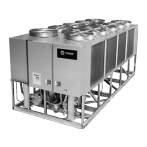
  9. Trane CGAH 115 Owner's manual

Trane CGAH 115 Owner's manual

This manual suits for next models

7

Other Trane Chiller manuals

Trane 4YCA4024A1060A Assembly instructions

Trane

Trane 4YCA4024A1060A Assembly instructions

Trane R Series Owner's manual

Trane

Trane R Series Owner's manual

Trane 4YCZ5036F1070B User manual

Trane

Trane 4YCZ5036F1070B User manual

Trane CVHE User manual

Trane

Trane CVHE User manual

Trane CenTraVac CDHH Installation and operating instructions

Trane

Trane CenTraVac CDHH Installation and operating instructions

Trane CVGF-SVU02B-E4 User manual

Trane

Trane CVGF-SVU02B-E4 User manual

Trane Sintesis RTAF Installation and operating instructions

Trane

Trane Sintesis RTAF Installation and operating instructions

Trane RTAF SE Series Owner's manual

Trane

Trane RTAF SE Series Owner's manual

Trane CGWF SE Owner's manual

Trane

Trane CGWF SE Owner's manual

Trane RTAA-130 Installation and operating instructions

Trane

Trane RTAA-130 Installation and operating instructions

Trane AquaStream2 CGAN 200 Owner's manual

Trane

Trane AquaStream2 CGAN 200 Owner's manual

Trane R Series Owner's manual

Trane

Trane R Series Owner's manual

Trane CenTraVac CVHM User manual

Trane

Trane CenTraVac CVHM User manual

Trane Picco R32-140 Instruction Manual

Trane

Trane Picco R32-140 Instruction Manual

Trane BAYECON102AA Assembly instructions

Trane

Trane BAYECON102AA Assembly instructions

Trane CCUF Owner's manual

Trane

Trane CCUF Owner's manual

Trane R Series Guide

Trane

Trane R Series Guide

Trane RTHC Owner's manual

Trane

Trane RTHC Owner's manual

Trane 2TTZ9C Assembly instructions

Trane

Trane 2TTZ9C Assembly instructions

Trane BAYLOAM103 Assembly instructions

Trane

Trane BAYLOAM103 Assembly instructions

Trane SINTESIS ADVANTAGE CGAF Series Owner's manual

Trane

Trane SINTESIS ADVANTAGE CGAF Series Owner's manual

Trane Water-Cooled CenTraVac S Series User manual

Trane

Trane Water-Cooled CenTraVac S Series User manual

Trane Flex II Series Owner's manual

Trane

Trane Flex II Series Owner's manual

Trane RTAA-70 Operating and safety instructions
Trane

Trane RTAA-70 Operating and safety instructions

Popular Chiller manuals by other brands

Carrier Omnizone 50BVC Installation, Start-Up, Service and Controls Operation and Troubleshooting

Carrier

Carrier Omnizone 50BVC Installation, Start-Up, Service and Controls Operation and Troubleshooting

York YGWH 115 Installation, commissioning & operation

York

York YGWH 115 Installation, commissioning & operation

Galletti PERFORMA MPE Series Technical manual

Galletti

Galletti PERFORMA MPE Series Technical manual

SMC Networks HRR Series manual

SMC Networks

SMC Networks HRR Series manual

Daikin EWAQ016CAW Installation and operation manual

Daikin

Daikin EWAQ016CAW Installation and operation manual

Moffat Friginox TSR-11SC Specification sheet

Moffat

Moffat Friginox TSR-11SC Specification sheet

Gree GWH07AGA-K6DNA1C Service manual

Gree

Gree GWH07AGA-K6DNA1C Service manual

MP Systems PURGE Series manual

MP Systems

MP Systems PURGE Series manual

Penguin COLD THERAPY CHILLER owner's manual

Penguin

Penguin COLD THERAPY CHILLER owner's manual

Telemark TVP-2000 Operation, installation and service manual

Telemark

Telemark TVP-2000 Operation, installation and service manual

TICA MINI VRF CHR Series Installation & operation manual

TICA

TICA MINI VRF CHR Series Installation & operation manual

MAXA A68 Installation and operation manual

MAXA

MAXA A68 Installation and operation manual

AERMEC NRL FC 2000 installation manual

AERMEC

AERMEC NRL FC 2000 installation manual

SABROE ChillPAC operating manual

SABROE

SABROE ChillPAC operating manual

Aqua Optima Corona Instructions for use

Aqua Optima

Aqua Optima Corona Instructions for use

Nordcap SKF 5 GN 1 manual

Nordcap

Nordcap SKF 5 GN 1 manual

lancer Siberian Elite Series Installation, operation & service manual

lancer

lancer Siberian Elite Series Installation, operation & service manual

York MILLENNIUM YT J Wiring diagram

York

York MILLENNIUM YT J Wiring diagram

manuals.online logo
manuals.online logoBrands
  • About & Mission
  • Contact us
  • Privacy Policy
  • Terms and Conditions

Copyright 2025 Manuals.Online. All Rights Reserved.

ïi
JnRAflE* CGAH
AÍr
cooled
liquid
chilfers
j
Instaf
lation
Operation
Maintenance
To
be
used
withmanual
for
module
SMM
reference
L80lM 019E
Sizes ilS - lZO
- tiS - ZZS
-
230
-235
_
240
-250
j
GrolM oozE
The
aim
of
this
document
for
users
is
to
set
out
the
rules
for
theinstallation,
set-up,
operation
and
maintenance
of
this
type
ofTrane
liquid
chilter.
Themaíntenance
operations
required
to insure
that
this
machine
operates
reliably
throughout
its
full
service
life
are not exhaustively
described.
only the services
of a
qualífied
technician
employed
by a reputabte
service
company
caninsure
that
themachine
operates
durably
andreliably.
warranty
is
based
on
the
general
terms
and
conditíons
of
société
Trane.
Thewarranty
is void if the equipment
is
repaired
ormodified
without
the
written
approval
ofTrane,
if
theoperating
limits
are
exceeded
orif
the
controlsystem
of
the
electrical
wiring
is
modified.
Damage
due
to misuse,
lack
of maintenance
orfailure
to
comply with the manufacturer,s instructions or
recommendations
is not covered by the warranty
obligation.
,-.1
Allair-conditioning
units
are
shipped
to
theirinstallation
site
on awooden
skid.
Allmachines
reach
final
destination
completely
connected
andassembled
ready
forimmediate
start-up.
Please
check
thatthe
unithas
not
in
any
way
been
damaged
during
the
transport,
assoon
asit
arrives
on
site.lf
damage
isobserved,
oreven
onsuspicion
ofdamage.
ó Carry
out instructions
for notification
of damage
in
transport,
and
warn yourTrane
Agency.
About
thismanualz
"Caution' and 'Warnings" messages
appear at the
appropriate
place
throughout
themanual.
Your personal
safety
and
the proper
operation
of this
machine
require
that
youfollow
them
carefully.
Trane
Europe
assumes
no liability
for instalrations
or
servicing
performed
byunqualified
personnel.
n1
Acceptance
ondelivery....,. .......................:.
...............2
Unitnameplafe
r " ...'........4
lnstallation
instructions.... ................4
Waterconnection
................... ..........,5
Wiring
diagram
-Customer
electric
power
supp1y.............. .......,.....,7
Unit
nameplate
The unit nameplate
gives
the complete
model reference
numbers.
The unit power rating is shown, and power supplies
should not deviate by more than 5% from the rated
power.
Compressormotoramperageis
shownin box
g.
The currentintensity
(shown
in amps)is the maximum
for the rated
operatingvoltage.
The customer's electricalinstallation
must be able to
withstand
thiscurrent.
lnstallation ihstructions
Foundations
No specialfoundations are required,
provided
the
supporting
surface
ísflat
and
level,
and
can
withstand
the
weight
ofthe unit.
Waterdrainhole
Insure
thereis a drainhole
wide enough
to drain
away
waterfrom the unit in the event
of shut-down
or repair.
Clearance
tnsure
there is sufficient
clearance
around
the unit to
allow maintenance
operations
to take place
without
obstruction.
Forminimum clearance
consult
thecertified
submittals,
whichareavailable
on request
from yourTrane
agency.
Handling
A (mm)
B(mm)
Maximum
weight (kg)
1500
1800
725
Moo€LE
-
Moocr.uoosr-t
x"l-- f--l t
'ERIE-sEn,or.sERrEN
n"
FT ctRcuÍT
cor{TRor.E
lliff$iilf,ïii'l3H
^"'Í-:l
I STnoÀ/TAUFNAHME lbYqEssE tN
|:PJ,*r...".g".1t:::,,
Ë Ëi-*Et*ffi Ë*.]
ICOMPRESSORMOTOíI -Lr
t,anó*nÉÀuciron
Efl t]
I uoteunvsrnLerEuncos
Irstrtlp&%;;
*" fl tl f-r
€vApoR^rEUR - EvApoMToR. vEnDAM*r* [---l
CIRCUTÍ-rÁLTÊxREIs coNTRoL
cIRcutT
I PRESSION
DESERVICE
EVPCOTEEAU -
I sERvrcEpnEssunEoFEVpwATERstDE | |
I EEIRIEESDRUCI(VERDAMPFER
WASSERSEMG
I CHA8GEOEREFRIGÊRANÏ
lÀsrÀièËm-r.riiiiÁê
" [--l*o o.[-l
I HLTEMÍTTELFULLUNG gJ
I pREsstoN
D'EpREuvÊ lltuTE. HtcH. HocH
I TESTPRESSUFE
I pn0roRucx 8,{SSE
. LOW.
NTEDER
SOCIETE
TRANE
88190
GOLBEY.
FRANCE
e rnArr
Water
to evaporator
connection
lnstall water circulation pump upstream of the
evaporator,
insuring
thatthe
evaporator
is
under
positive
pressure.
Tables
forpower
supply
connections
andwaterreturn
are
shownon thecertifiedsubmittals.
Thesedrawings
areavailable
on requestfrom
your
Trane
agency.
The 114coupling
located
on the outletconnections
may
be used as the draining outlet from the plate heat
exchanger.
The
following recommendations
refer
to Figure
2.
1. Pressure
gauges:
showsenteringand leavingwater
pressure.
Stop valvesshould be provided
on water
inlets
and
outlets.
2. Vibrationdampers:
theseare suppliedas standard
with themachine,
andshould
be
placed
between
the
suppoftingfloor and the unit to prevent
vibrations
beingtransmitted
to thechilledwater
circuits.
3. Thermometers:indicate
chilledwater entering
and
leavingtemperatures.
4. Balancing
valve:
controlswaterflow
5. Stop valves: isolate
chillersand water circulating
pumpduringmaintenance
operations.
lnsure
that all chilled
water.
pipes
arefullyinsulated,
in
order
to prevent
frost
damage.lnsulate
heating
resistors
on allwater
pipes
exposedto negative
temperatures.
Minimum water capacity
Minimum volume of water in the chilledwater circuit
must be no less than 10% of the volume of water
circulating
per
hour
intheunit.
lf necessoN,
a buffer tank should be fitted.Safety
and
regulation
devices
will only operate
correctlyif there is
sufficient
water inthe system.
Figure2 - Water-to-evaporator
connection
Pressure
gauge
Balancing
valve
Watertreatment
Untreatedor insufficiently
treatedwater,
if usedin this
unit,may causescale,
slinreor algae
to accumulate
or
causeerosionandcorrosion.
Theservices
of a qualified
water treatment specialist are recommended to
determine
what treatment,if any, is advisable.
Trane
disclaims
any
liability
with
regard
todamagearising
from
theuse
of untreatedor improperly
treatedwater,
or from
theuseof salineor brackish
water.
Stopvalves
Expansion
compensators
Stopvalves
Evaporator
ff."
Generalunit characteristics
(11
Maximum load amps to be used for sizingoí cables,
fusesand disconnect
switch
(21
Starting amps with one coÍnpressorstarting ,theremaining compressor(s)
running at full load
Fuses
107 2sA
157 404
Eachcompressor
is supplied
with its
own fuses.
{,
Size 115 120 125 zz5 230 235 240 250
Compressors 'l0T+107 10T+157 15T+157 (10T+10T)+157
(10T+15T1+157
(1!iT+l5T)+157 2X(10T+15T)2X(15T+15T)
Circuit 1t122222
Capacity control ïo 50 58ou
42 50 7sl30 70F'4 66t33 80t50/20 75FAn5
Maxload
amps
(1)
28bar
disch.
5barsuct. 380V A 42 53 64 74 85 96 106 128
4't5V A39 49 59 69 79 89 97 118
Nomínal load amps
25bar disch. 5 bar suct. 380V A38 48 58 67 77 87 96 116
415V A35 14 54 62 71 81 88 107
Startingamps (2) 380V A107 143 154 163 173 183 196 218
415V A1lil 158 168 176 185 195 207 227
Control cir. amos 230V A1.8 1.8 1.8 2.8 2.8 2.8 2.8 ?.8
Evaporatorwater volume Litres 3.76 1.7 5.66 7.52 8./to 9.12 9.42 11.32
Number of fan(s) 12222ou3 2ou3 2ou3 2ou3
Condenserair flow m3/s 4.25 4.96 6.61 1.46 8.4 9.5 11.8 11.8
Nominal fan sDeed revlmn 5.5 r0.9 10.9 10.9 16.3 16.3 21.9 21.7
Fan motor kW each kw 1.2 1.2 1.2 1.2 1.2 1.2 1.2 1.?
Fanmotor
staningamps
(3) 380V A14.1 14.1 I4.1 14.1 14.1 14.1 1
tl.1 14.'l
415V A15.4 15.4 15.4 15.4 15.4 15.4 15.4 15.4
Fanmotor full load amps (3) 380V A3.9 3.9 3.9 3.9 3.9 3.9 3.9 3.9
415V A3.6 3.6 3.6 3.6 3.6 3.6 3.6 3.6
Unit oil charge Seesubmittal
Weiqht 725 850 975 1250 1375 1425 15s0 1750
Coolins fluid charqe Seesubmittal
See
submittal
Seesubmittal
Seesubmittal
Lenght
width
Heiqht
NOTES:
Wiringdiagram
- customer
electric
powersupply
#ï" !:.:
------__-_-.t.!-
tl
ll
T-'- | I
i \\'i
q--.1-1.
tl
...J
I
::::::
l-r
rl
t}
iffiÏ
'-li'1,{,{i
\
T--
E_-
l
Repère
@Options
Démarrage
pompe
EVP. Zubehoer
Anlauf.Wasserpum
pe
VERD. Options
EVPV1/ater
pump
start
oInterrupteur
unité Hau
ptschalter
Maschine Disconnect
switch
oRésistance
coffret HeizungSchaltschrank Control
panel
heater
@Transfo.
alimentation
contróle Transformator TransÍormer
oSondedetempérature FuehlerTemperatur Temperature
sensor
CàblageTrane Trane-Verdrahtung WiringbyTraner
CàblageClient Verdrahtung
durchKunden Wiringby
Customer
3.
4.
5.
6.
Unitstart-up
Before
start
up,carryoutalloperations
onchecklist
and
follow the instructions
belowto ensure
thatthe unit is
correctlyinstalled
and ready
to operate.
The installer
must check
all the following
points
before
calling in the Traneservicing
Department
to put the
equipmentinto
service.
1. Chilledwater circuit ready to operate,
filled with
water,
pressure
test
carried
out,purged,
filter
cleaned
after2 hours
operation
ofthechilledwater
pump.
2. Thermometers and pressuregauges installed
on
chilledwater
circuit.
Chilledwatér
pumpinterconnected
tocontrol
panel.
Check
that all electrical
connections
are clean
and
sound. Check
that circuitscomply with the wiring
diagram
supplied.
Technical
datashown
at
thetopof
the wiring diagram should match the information
shownon the unitnameplate
plate.
Check
thatmains
power
supplyswitch
is
sound.
Check
compressor
oil level
at rest.
Thelevel
should
reach at least halfway up indicator located on
housing.
Seefig 4.forcorrect
level.
Check direction of rotation of compressors
using
phasemeter.
8. On start-upof each motor in the system,
check
the
direction of rotation and operation of all the
components
they
drive.
9. Checkextent
of pressure
drops
through
evaporator,
sothat
thevalue
matches
values
shown
ongraphs
A
andB.
10.
Checkthatthereis sufficient
demand
for cooling
on
thedayof start-up
{around
50%
ofnominal
load).
Differential
water pressure
switch:
lf the unit pressure
switch is adjustable,
please
refer
to
information
sheet
available
from your
Trane
agency,
and
adjustthe setpoint
as required.
Someunits
have
preset
pressure
switches
alreadyfitted,
andthese
should
notbe
changed.
Figure
4 - Compressor
oil level
Preparation
Before
stafting
up the system,
carry
out the following
checksand
operations:
1. Before
making
any
eleictrical
connection,
insure
that
theisolation
resistance
of
all
power
supply
terminals
to
ground
complies
with
standards
and
regulations
in
force.
Check
the isolation
c,f
all etectric
motors
using
a
500V DC
megohmeter
which
meets
manufacturer's
specifications.
2. Check
that all electrical
connections
are clean
and
sound.
Insure that circuits comply with the unit wiring
diagram.
The
technical
data
shownat
the top of the
wiring
diagram
should
match
theinformation
shown
onthe unitnameplate.
Switchon mainspow€rt,
supplyswitch.
Checkthat unit power supplies
match rated input
power.
5. Insure
all water and refrigerant
vatves
arein service
positions,
and
start
upwater
circulation
pumps.
6. Reset
all manually
setcontrol
devices.
7. Insure
sensor
isproperly
installed
inits
bulbwell
and
submerged
in heat
conducting
product.
Checkfixing
of capillarytubes (chr:ck
protectionfrom vibration
and from wear, ancl insure that they are not
damaged).
Start-up
1. Start-up
chilled
water
pump or pumps.
2. Start-upeach compressor
turning switchesS1, 52,
53, or S4 separately.
lf one of the compressors
will
notstartup,
check
the foltowing points:
a) SMM control modute should be in 'cooting.
position.
b) Connection
between
the unit and chiiled
water
pumpcontactor
nlust
bemade.
7.
3.
4.
Max.
oil
level
Min.
oillevel
3. After unitstart-up,
leave
in operationfor at least
1S
minutes,
to insure
pressure
is
stabilized.
Thencheck:
- compressor
and
powered
fanpower
consumption
- suction
pressure
- discharge
pressure
- theliquid
sightglass(es)
- superheat
- subcooling
- pressure
drops
andtemperatures
ofevaporator.
All measurements
andreadingsfrom pressure
gauges
mustberecorded.
according
to theprocedures
setout
below:
Liquidline
sightglass
The refrigerant
should be seen to flow through the
sightglass
in a regular
manner,
and befree
of bubbles.
Bubbles
area signthatthereis not enoughrefrigerant,
andof a possible
leakorobstruction
onthe
liquid
line.
Each
sightglassisfitted
with a moisture
indicator.
Asthe
refrigerant
flows through,
the sightglasswill showthe
degreeof rnoisture
in
therefrigerant.
Thisreading
is
also
temperature
dependent.The indicator
shouldshow dry
refrigerant.lf
"moist
refrigerant"
id
displayed,keep
unitin
operationfor atleast
twelvehours,and
check
again.
Superheat
Normal
superheat
is
7"-1OoK
onthe
standardunit.
Excess
power
supplied
to theevaporator
produces
high
suction
pressure,
and a low degree
of superheat
candrawthe
refrigerant
back
the
compressor.lnsufficient
superheat
is
corrected by adjusting the expansion valve reduction
lever.lf this produces
no result,
it shows
thateither
the
expansionvalve
bulbor shuttervalve
seatareno longer
operating
satisfactorily.
Thedefective
component
must
to
be replaced.
Sub-cooling
lf the system
iscorrectly
filled,
the sub-cooling
value
of
therefrigerant
valve
onthe liquidline
should
beB"-1OoK
on a standard
unit.
Condensorfan motors
All fans are secured directly to the motor shaft. The
operating
sequence
of fan motors is controlled
by the
SMMmodule.
Refer
to theIOM
oftheSil\4M
control
module.
Low temperatureoperations
(air
intake
to condenserl
lftheunitis
settooperate
at
alow
air
intake
temperature,
follow procedures
below to insure the chilled water
circuit
is properly
protectr:d.
Switchon power to evaporator
and water pipeheating
resistors.
lnsure that all pipes are perfectly protected
againstfreezing
Use
antif
reeze
solution
inchilled
water
circuit.lf forany
reason,
the heating
resistors
in the chilled
water
circuit
cannotbe suppliedwith current,
the solutionmust be
able
to withstand
anyice
formation
inthecircuit.
When
using the antifreeze solution, manufacturers,s
instructionsÍor filling o1'
the chilled
water circuit,
the
degree
of protection
andtestprocedures
must bestrictly
followed.
Final
check
Bringunit into operation
on a stage
by stage
basis,
to
meetchanging
levels
in
tlre
degree
ofcooling
required.
Oncethe unit is operating
as it should,
a final check
shouldbemade
forthefollowing
points:
1. Checkthatunit
is
clean,
and
clear
ofany
debris,
tools,
etc.
,Allvalves
in operating
position.
Closecontrol and starter panel doors, and check
panels
are
fixed.
2.
3.
800
.sl
o
)i
(!
E
lu
J
()
F
o
d)
o
6
o
o
E
(\l
.9t
o
.Ê
F
z
C>
co
(\l
/.
FigureA - Evaporator
pressure
dropswith
R134a Figure
B - Evaporatorpressure
dropswÍth
R22
rO
80
€o
50
ao
30
9.
t0
t
f
6
5
to
00
5{t
,.(,
gt
Ê*
ê
ro
t
I
6
5
tr Il
lll 1,T,'/,
/t
Á1r T-7r
J
R22 1t /,
/,
/,
,//, / /
t
]
System regulation
Regulationis
through
the
SMM control
module.
Refer
to the module
IOM
N" L80
lM 019
E
A sensoris placed
in the bulbwell
on evaporator
water
leaving
side,whereit registers
waterleaving
temperature
from evaporator.
Unit operations
Switch on fused mains power switch to chilled water
circulation
pump,
and
start-up
pump.
Unit will start up when S1 switchin control/command
boxswitches
to position
1(S2
switchto position
1,
etc.).
The unit will operatecorrectly
when there is sufficient
waterflow atthe evaporator.
Thecompressor{s}
will start
up if the evaporator
water leaving
temperature
is above
theSMM control
module
setpoint.
The
SMMcontrol
module
willreact
based
ontheincrease
or decreasein the evaporator
wateroutlettemperature.
Weeklystart-up
1. Startupchilledwater
pump.
2. Switch
51to position
1,starting
upunit.
Weekendshutdown
lfthe unit needs
to beshutdown for ashorttime,switch
51to 0.
lf the unit is shut down for a longer
period,
seeunder
'Seasonal
shutdown', below.
Seasonalshutdown
{Requi
res
qualified
technician}
1. The evaporator
may be drainedby opening
the U4
connection
on the wateroutletpipe.
2. Switchoffmains
power
supply
switch.
Ensure
that
it
cannotbeswitched
on'while
theunitis
atrest.
Seasonalstart-up
(Requires
qualified
techniciian)
1. Ensureallthe instructions
in "Annual
maintenance.
instructionsmanual,
in the "maintenance'
chapter,
havebeencomplied
with.
2. Fillup andpurge
chilled
water
circuits.
3. Insureliquidline
stop-valve
isopen.
4. Check
for possible
leak:;
in system.
5. Switchon 51 switch
to 0
6. Switchon main powersupplies
to system.
7. Startup system.
8. Checkallinterconnecterj
devices
operate
properly.
9. Checkoil level
andservice
pressures
after
thesystem
hasbeeninoperation
for 15
to 20minutes,
under
full
load.
10.Checkrefrigerant
flow is regular.
lf bubblesappear,
checkfor possible
leaks;
in system.
11.Check
that high and low pressures
are corrêct,
as
requiredfor thetype of unit manufactured.
10