N‐i‐HPInverterair/waterheatpumpchillerswithaxialfans
2
INDEX
1AIMANDCONTENTSOFTHISMANUAL...............................................................................................................................4
1.1HOWTOKEEPTHISMANUAL.................................................................................................................................................4
1.2GRAPHICSYMBOLS................................................................................................................................................................4
2SAFETYLAWS......................................................................................................................................................................4
3PERMITTEDUSES................................................................................................................................................................4
4GENERALSAFETYGUIDELINES.............................................................................................................................................5
4.1WORKERS’HEALTHANDSAFETY............................................................................................................................................5
4.2PERSONALSAFETYEQUIPMENTS...........................................................................................................................................5
4.3SAFETYSYMBOLS...................................................................................................................................................................5
4.4REFRIGERANTSAFETYDATASHEET........................................................................................................................................6
5TECHNICALCHARACTERISTICS.............................................................................................................................................7
5.1FRAME...................................................................................................................................................................................7
5.2REFRIGERANTCIRCUIT...........................................................................................................................................................7
5.3COMPRESSORS.......................................................................................................................................................................7
5.4AIR‐SIDEEXCHANGERS...........................................................................................................................................................7
5.5FANMOTOR...........................................................................................................................................................................7
5.6USER‐SIDEHEATEXCHANGERS..............................................................................................................................................7
5.7ELECTRICALCONTROLPANELBOARD....................................................................................................................................7
5.8CONTROLSYSTEM..................................................................................................................................................................7
5.9MONITORINGANDPROTECTIONDEVICES.............................................................................................................................8
5.10HYDRAULICCIRCUIT...............................................................................................................................................................8
5.11FANSPEEDCONTROL.............................................................................................................................................................8
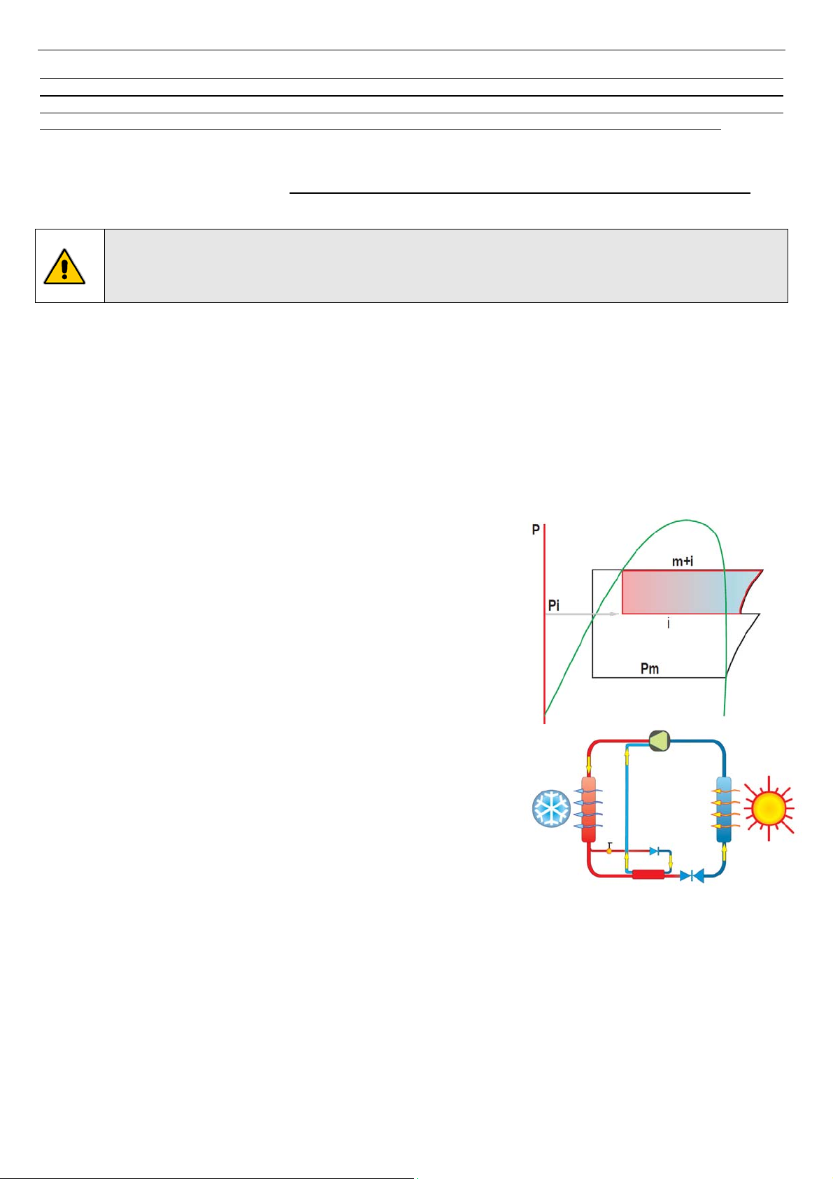
5.12ENHANCEDVAPOURINJECTION(EVI)TECNOLOGY...............................................................................................................8
6AVAILABLEVERSIONS,SIZESANDACCESSORIES..................................................................................................................9
6.1OPTIONALACCESSORIES......................................................................................................................................................10
7INSTALLATION..................................................................................................................................................................11
7.1GENERALITY.........................................................................................................................................................................11
7.2LIFTINGANDHANDLING......................................................................................................................................................11
7.3LOCATIONANDMINIMUMTECHNICALCLEARANCES..........................................................................................................11
7.4HYDRAULICCONNECTIONS..................................................................................................................................................12
7.4.1Drainageconnection....................................................................................................................................................12
7.4.2Servicevalve.................................................................................................................................................................12
7.4.3Plantdrainagesystem..................................................................................................................................................12
7.4.4Hydrauliccircuit...........................................................................................................................................................13
7.5REFRIGERANTDIAGRAMS....................................................................................................................................................13
7.5.1RefrigerantdiagramofthemodelN‐i‐HP0125...........................................................................................................13
7.5.2RefrigerantdiagramofthemodelN‐i‐HP0235‐0250..................................................................................................14
7.5.3RefrigerantdiagramofthemodelN‐i‐HP‐LT0125......................................................................................................14
7.5.4RefrigerantdiagramofthemodelN‐i‐HP‐LT0235‐0250.............................................................................................15
7.6ELECTRICALCONNECTIONS..................................................................................................................................................15
7.6.1Wiringterminalblock...................................................................................................................................................16
8STARTUP..........................................................................................................................................................................18
9POWER‐ONOFTHEUNIT..................................................................................................................................................19
10SHUTDOWNSFORLONGPERIODS.................................................................................................................................19
11MAINTENANCEANDPERIODICALCONTROLS.................................................................................................................19
11.1ENVIRONMENTALPROTECTION...........................................................................................................................................19
12WHENTHEUNITGOESOUTOFSERVICE........................................................................................................................20
13TECHNICALDATA(PRELIMINARIES)...............................................................................................................................20
13.1STANDARDVERSION............................................................................................................................................................20