T.MIX DPM-1122 User manual

Owner‘s Manual
POWER MIXER
with 24-bit Digital Effects
DPM-1122

2
Contents
Important Safety Instructions! ..........................................................................................................................3
Cleaning and Care .......................................................................................................................................3
Introduction .................................................................................................................................................4
Features ............................................................................................................................................................4
Quick Start........................................................................................................................................................4
Becoming acquainted with the Operational Surface........................................................................................5
Small Gig Hookup Diagram .........................................................................................................................6
Computer Set-up Diagram ..........................................................................................................................6
The Control Elements . . . .................................................................................................................................7
. . . on the front Panel ..................................................................................................................................7
. . . on the rear Panel..................................................................................................................................12
Installation and Connection.......................................................................................................................12
Audio Connections ....................................................................................................................................13
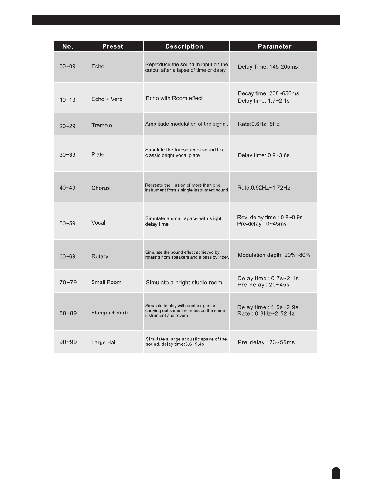
Preset List........................................................................................................................................................15
Block Diagram ................................................................................................................................................16
Technical Specifications ...................................................................................................................................17
Disposal ..........................................................................................................................................................18

3
Important Safety Instructions!
For your own safety you must read through this chapter at rst completely!
Risk of electrical shocks.
Only connect the device to a properly wired and earthed mains power socket providing mains voltage of•
230 V ~ /50 Hz.
Do not operate the device if the power cord or the mains plug are damaged.•
Never submerse the device in water. Wipe it with a slightly moistened cloth only.•
Do not expose the device to rain and never use it in a damp or wet environment.•
Make sure that the power cord never becomes wet or moist during use.•
Under no circumstances may you open the device housing. Should you do so your safety would not be as-•
sured and the warranty will become void. There are no operational components whatsoever inside, only re-
ally high voltage that can give you a deadly shock!
Do not place objects containing uids, e.g. ower vases or beer bottles, on or near the device.•
Notice regarding disconnection from mains-power:•
To completely disconnect the device from mains power, you must pull the plug from the power socket. For
this reason the device must be placed in a position where unobstructed access to the power socket is as-
sured at all times, so that in an emergency you will be able to immediately pull out the plug. To eliminate the
risk of re you must completely disconnect the power plug from the power socket when the device is not go-
ing to be used for a long time, for example, during holidays.
Always grasp the power cord by the plug. Do not pull on the cord itself and never touch the power cord with •
wet hands as this could result in a short circuit or an electrical shock. Do not place the device, speakers or
anything else on the power cord and make sure that it does not become clamped. Never tie knots in the
power cord and do not bind it together with other cables. Lay the power cord so that no one can step on or
stumble over it. A damaged power cord can cause a re or an electrical shock. Check the power cord from
time to time. Should it become damaged contact our customer service department to have it replaced.
Always operate the device only on a correctly earthed socket, never sever the power cord‘s earth wire. Oth-•
erwise a LIFE THREATENING situation exists!
Riskofre!
Never leave the device unattended during operation.•
Never cover the ventilation slots of the device while it is on. Do not place the device in locations that are •
subject to direct sunlight. If you do, it may overheat and become irreparably damaged.
Do not operate the device on surfaces that restrict normal airow around the device, for example, a bed, •
sofa, carpet or similar surfaces.
Never operate the device in the vicinity of heat sources such as cookers, heating elements or other heat •
producing installations.
Do not place open re sources, such as candles, on the device.•
Before a storm and/or a thunderstorm with a risk of lightning, please disconnect the device from the electri-•
cal power source.
Riskofpersonalinjury!!
Keep children away from the power cord and the device. Children frequently underestimate the dangers of •
electrical devices.
Provide a stable location for the device.•
Do not operate the device if it has sustained a fall or is damaged. Have the device checked or, •
if necessary, repaired by qualied technicians.
Keep sufcient distance from speaker boxes when operated with high volume level. Listening to •
music with high sound pressure level may cause permanent damage to your hearing!
Cleaning and Care
NEVER submerse the device or its components in water or other uids! Do not allow any liquids to pen-•
etrate the housing. This would damage the device or cause a short circuit.
Cleaning the housing: Remove the power plug from the power socket beforehand. Clean the housing sur-•
face with a slightly damp cloth Never use petrol, solvents or detergents that can damage the units surface!

4
Introduction
Thank you for your purchasing of THE T.MIX DPM 1122 16-channel Power mixer with 24-bit digital multi-effect
built-in. Your THE T.MIX DPM 1122 is a remarkable compact powered mixer that doesn’t nd many equals in
the market today. With 12 microphone and 2 stereo line-level inputs for serious live performances, your THE
T.MIX DPM 1122 also includes a 24-bit digital multi-effect with 10 factory presets and 10 variations for every
preset, for a total of 100 different digital effects. There is a three bands EQ on mono input channels, four bands
EQ on stereo input channels. Use it for small gigs, church applications or conference.
Enjoy your THE T.MIX DPM 1122 and make sure to read this manual carefully before operation!
Features
12 MIC inputs, 2 stereo inputs, 2 AUX stereo inputs, 1 RCA 2-track input and 1XØ3.5 AUX stereo
input.
MONO channels:X
Low-distortion MIC preamp with high dynamic range.
Balanced XLR and TRS inputs.
Lowcutlters75Hz18dB/octoneachchannel.
3-band swept mid EQ on each channel.
+48VphantompowerwithoneswitcheveryfourMICinputs.
STEREO Channel:X
Balanced TRS inputs.
+/-20dBsignallevelcontrols.
4-band EQ on each channel.
MUTE,PFLswitches,PEAKLEDandahigh-quality60mmfaderoneachchannel.X
4AUXsends:AUX1/2areconguredasswitchablePRE/POST,AUX3/AUX4forinternalDSP&X
discrete output.
2 built-in DSPs sending signal to AUX sends or main mix bus.X
7-bandgraphicEQ.X
CompressorwithvariablethresholdandratioonMAINMIXbus.X
12segmentsignallevelmeters,usePFL(AFL)/MAINMIXswitchtochangePHONES/CTRL-ROOMX
output signal.
Built-inhigh-qualityDclassamplierwithsignal,CLIP,andprotectionLEDs.X
Quick Start
This is the fastest way to get something out from your THE T.MIX DPM 1122, if you have a keyboard and a
microphone.
1. Plug the microphone into channel 1 MIC IN.
2. Turn down AUX and LEVEL controls on that input channel.
3. Put the EQ controls on centre position.
4. Connect 2 passive cabinets to the rear speaker output sockets.
5. Turn on your THE T.MIX DPM 1122.
6. Sing or speak into the microphone with normal volume and adjust the channel fader of half.
7. If you like, you can adjust the EQ at this stage.
8. The CLIP LED on the L/R master LED meter should ash only occasionally, otherwise you will hear distor-
tion. If this LED is not active and you still hear distortion, please turn down a little the input TRIM control.
10. Connect a stereo keyboard to channel 13/14 and repeat the above sequence. If the CLIP LED is not ac-
tive but you hear distortion, please reduce the output level of the source instrument
Here you are. It is your rst gig with your THE T.MIX DPM 1122.

5
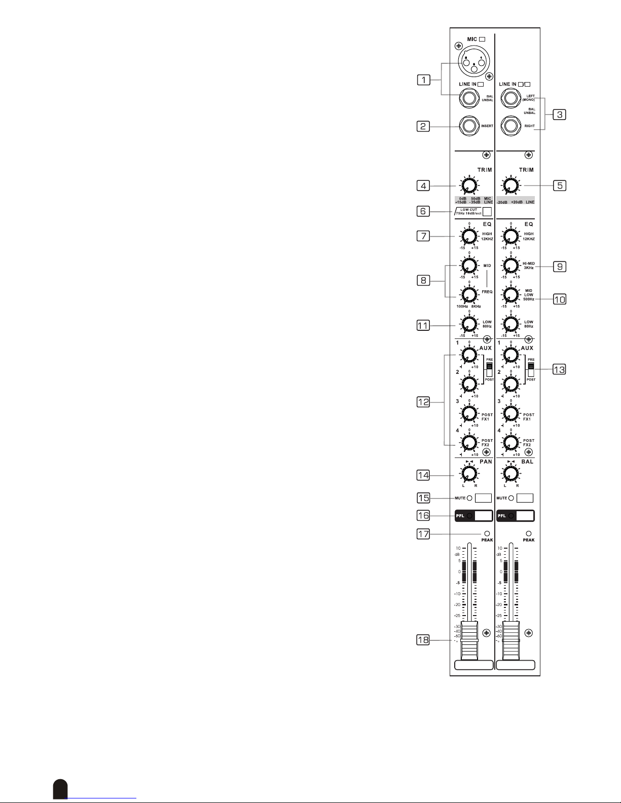
Becoming acquainted with the Operational Surface

6
Small Gig Hookup Diagram
(the displayed amplier is optional - of course you can connect the speakers to the
speaker sockets on the rear panel of the mixer.)
Computer Set-up Diagram

7
The Control Elements . . .
. . . on the front Panel
1. TheMONOMIC/LINEChannels
Your THE T.MIX DPM 1122 is equipped with 12 low-noise microphone
preampliers with optional phantom power, 50 dB of gain and over
100dB of S/N ratio. You can connect almost any type of microphone.
Dynamic microphones do not need phantom power. Use phantom power
only with condenser microphones but make sure that the phantom power
button is disengaged before connecting the microphone. Phantom power
will not damage your dynamic microphones, so make sure to read the
microphone instructions manual before engaging phantom power. These
channels are also equipped with 1/4“ TRS balanced/unbalanced LINE-
IN plugs to connect line-level instruments such as keyboards, drum
machines and effect devices.
2. MONO Channel INSERT
This is where you connect external sound processors such as
compressor-limiter, equalizers, etc. The insert point is available on the
rst 12 MIC channels only. For the other channels you can always insert
the processor in between the sound source (such as keyboard or drum
machine) and the THE T.MIX DPM 1122 input. The insert sockets can be
used as direct-outs to feed the input of a multi-track recorder.
3. STEREO INPUTS
These are channels 13/14 and 15/16. They are organised as stereo pair
and provided with 1/4” TRS phone sockets. If you connect only the left
jack, the input will operate in mono mode, that is the mono signal will
appear on both mix channels. You can use these inputs with a stereo
keyboard, drum machine, etc.
4. MONO Channel TRIM
This control is provided with 2 different indications: One is for the MIC
and the other for LINE levels. When you use a microphone, you should
read the MIC ring (0~-50dB); when you use a line level instrument,
you should read the LINE ring (+15~-35dB). For optimum operation
you should set this control in a way that the PEAK LED (17) blinks only
occasionally in order to avoid distortion on the input channel.
5. STEREO Channel TRIM
When you use a line level instrument, you shall read the ring (+20~-
20dB).For optimum operation you shall set this control in a way that the
PEAK LED (k) blinks only occasionally in order to avoid distortion on the
input channel.
6. LOW-CUT Button
By pressing this button you will activate a 75 Hz low frequency lter with
a slope of 18 dB per octave. You can use this facility to reduce the hum
noise infected by the mains power supply, or the stage rumble while
using a microphone.
EQUALISER
There are 3 bands EQ with sweepable MID on all mono input channel
1-12: HI, MID and LOW band.
There are 4 bands xed frequency EQ on the stereo channel 13-16: HI,
HI-MID, MID-LOW and LOW band. All bands provide up to 15 dB of boost or cut.
8
7. HI
If you turn this control up, you will boost all the frequencies above 12
kHz (shelving lter). You will add transparency to vocals and guitar and
also make cymbals crispier. Turn the control down to cut all frequencies
above 12 kHz. In such way you can reduce sibilance of human voice or
reduce the hiss of a Tape player.
8. MID
This is a peaking lter and it will boost/cut frequencies from 100 Hz to 8
kHz depending on the position of the MID freq control. This control will
affect especially upper male and lower female vocal ranges and also
the harmonics of most musical instruments.
9. HI-MID
This control gives you up to 15 dB boost/cut at 3 kHz. It is useful for
controlling voices. You can accurately polish your performance via
adjusting this knob.
10. MID-LOW
This control gives you up to 15dB boost or cut at 500Hz.
11. LOW
If you turn this control up, you will boost all frequencies below 80Hz.
You will give more punch to bass drum and bass guitar and make the
vocalist more “macho”. Turning it down, you will cut all the frequencies
below 80Hz. In this way you can avoid low-frequency vibrations and
resonance, thus preserving the life of your woofers.
12. AUXSENDSLevelControl
These four controls are used to adjust the level of the respective signal
sent to AUX bus, AUX1 and AUX2 can be switched to PRE/POST-
FADER via the PRE/POST switch, so, generally, they can be used
for monitor application and effects & sound processors input. AUX3
and AUX4 are congured as POST-Faders. In this typical compact
unit, excluding sending out the signal directly to the external effect
or processor equipment, AUX SEND3/4 can also be assigned to the
internal onboard effect module.
13. PRE/POSTSwitch
This switch is used to select pre- or post-fader for signal sent from input
channel to AUX sends bus 1-2. When you turn this switch to “pre”, the
pre-fader signal will be sent to the corresponding AUX bus pair.
14. PAN/BALControl
Abbreviation of PANORAMA control for mono channels, or the stereo
channels, always says, BALANCE control. Keep this control in centre
position, then the signal will be positioned in the middle of the stage.
15. MUTESwitch&LED
Each channel is equipped with a MUTE switch. The LED next to it
illuminates, when the MUTE section is activated. Pressing this switch
is equal to turning the fader down, which can mute the corresponding
channel output except for the channel INSERT send.
16. PFL(pre-faderlisten)Switch&LED
Each channel has a PFL switch which will send a signal from a post-EQ pre-fader location to the AFL/
PFL mix bus. This LED illuminates when the PFL is turned down. Use this when you wish to use the
headphones to monitor only a specic channel. Moreover, you can monitor a channel no matter the
channel fader is lowered or the MUTE switch is on when this PFL switch is engaged. This will not affect
the signals that are sent to the MAIN MIX bus and AUX buses.

9
17. PEAKLED
Inside your DPM 1122 the audio signal is monitored in several different stages and then sent to the PEAK
LED. When the LED is red illuminated, it warns you that you are reaching signal saturation and possible
distortion. Then you should reduce the input level for avoiding distortion.
18. FADER
This fader will adjust the overall level of this channel and set the amount of signal sent to the main mix.
19. +48VoltPhantomPower&LED
It is available only to the XLR MIC sockets. This LED illuminates when
power is switched on. Never plug in a microphone when phantom power
is already on. Before turning phantom power on, make sure that all faders
are down. In this way you will protect your stage monitors and main
loudspeakers.
20. LAMP
This lovable LAMP is very convenient for your operation, it is located in the
top right corner of the front panel, and provides the 12V socket that can drive
standard XLR-type (pin1 is for ground, pin 2 is for live terminal, pin3 is not
connected) lamps.
Note: don’t connect a microphone to this jack, otherwise, the microphone would
be damaged.
21. AUX IN
This 3.5 mm Ø stereo jack joins the same mix bus with the Tape IN input. It can
be connected to MP3- or CD players, computers, etc.
22. 2-TRACKIN/OUT
- TAPE IN: Use the Tape input if you wish to listen to your mix from a Tape
or DAT Recorder.
- TAPE OUT: These RCA jacks will route the main mix into a tape recorder.
23. AUX RETURNS
Use these stereo 1/4’’ sockets to return the sound of an effect unit to the main
mix. You can also use them as the extra auxiliary inputs, but they are primarily
used to connect the output of external processors.
DSP SECTION
There is a powerful 24-bit/100 presets digital multi-effects included in your DPM
1122. Effects include reverbs, chorus, anger, delay, and combinations of the above.
24. PRESETSelector&DISPLAY
Adjust this knob to select the right effect you wish to perform and the display
interface indicates selected preset. There are totally 100 options for you: Echo,
Vocal, Plate, and versatile two-effect combinations. When you are satised with the
right preset, please push this knob to store this preset you want.
25. PEAK/MUTESwitch&LED
This switch is used to activate/deactivate the effect facility. Sometimes, you can also
use the FX FOOTSWITCH (4%) for convenient operation. The LED lights up when the
signal sent to effect is too strong, in case of the digital effect module being muted,
this LED also lights up.
26. FX1TOAUX1/FX2TOAUX2LevelControl
This knob is used to adjust the level of the processed signal which is sent from the
DSP to AUX1/2 bus.

10
27. FX1/2TOMAINLevelControl
This fader is used to adjust the level of the processed signal which is sent from the
DSP to MAIN MIX bus.
28. AUX1-4Controls
These knobs are used to adjust the amount of the signal sent from the AUX
SENDS1-4 jacks to the AUX1, 2 ,3 and 4 buses.
29. 2-TRACKINLEVELControl
This knob is used to adjust the level of the signal sent from the 2TR
IN and AUX IN jacks to the MAIN MIX bus. The adjustable range
goes from -∞ to +10dB.
30. AFLSwitch&LED
When this switch is ON, the LED will light up and the output signal
that passes through the corresponding fader or knob is sent to the
AFL/PFL mix bus.
31. PHONES/CTRL-ROOMControl
This knob is used to adjust the level of PHONES output, which can
be varied from -∞ to +10dB.
32. AFL/PFL/MAINSwitch&LED
By pressing the switch, you can choose the output signal source of PHONES/CTRL-ROOM. When the
switch is OFF, the stereo LED meter will indicate the signal level of MAIN MIX OUT outputs, when the
switch is ON, the AFL/PFL LED lights up. Then the LED meter indicates the signal level of AFL/PFL mix
bus.
33. LED METER Display
The LED meter display indicates the output signal level.
34. STEREOGRAPHICEQ
Each one of these faders will boost or attenuate the selected frequency at
a preset bandwidth. When all faders are in centre position, the output of the
equalizer is in at response.
35. EQSwitch&LED
Engage this button to add the stereo graphic EQ into the main mix output
circuit, also the LED lights up. It can be used to modify the frequency
“contour” of a sound. If you release the button free, the stereo graphic EQ
will be bypassed.
36. POWER LED
This LED will light up when the unit is powered on.
37. THRESHOLDControl&LED
The threshold control has a range of -40 to +22dB, allowing applications
from low level compression to high level limiting. The threshold control
determines the audio level above which level reduction occurs. When the
signal peaks exceed the selected threshold, the LED lights up and level
reduction occurs.
38. RATIOControl
This control determines the ratio of change in output level to change in input
level for signal above threshold. If the output remains constant no matter
how high the input level, we have an innite input/output ratio. It should
be remembered that the control has no effect on signal portions below
threshold.

11
39. COMP./BYPASSSwitch&LED
Push this switch, the LED will light up and you will activate the MAIN MIX COMPRESSOR. You can also
use the bypass switch to make a comparison between processed and unprocessed signal.
40. AUXSENDSConnectors
These 1/4” phone jacks are used to send out the signal from the
AUX bus to external devices such as effect units and/or stage
monitors.
41. MAIN MIX OUT
These jacks are used to output the signal of the MAIN MIX bus.
The nal output level from these jacks is adjusted by the MAIN
MIX fader.
42. MONO OUTPUT Jack
Use this MONO jack to connect the input of an external amplier
or active monitor speaker.
43. PHONESJack
This jack will be used to send the signal to a headphone or to a
pair of powered studio monitors.
44. FOOTSWITCHJack
This 1/4” jack can be used to connect an external foot switch to turn on/off
the onboard effect module.
(TIP terminal controls FX1, RING terminal controls FX2, sleeve terminal
connects common terminal.)
45. POWER AMP Switch
This switch is used to control the amplier input signal.
46. POWER AMP. MODE Switch
This switch provides three modes: MAIN L/MAIN R;
AUX1/AUX2; BRIDGE. Select any one of these modes
to specify the signals to be routed to the corresponding
jacks according to the speaker connection at the speaker
jacks on the rear panel. For details please refer to later
content.
47. SignalLED
This LED will light up when the signal at the output is at least 100mV.
48. CLIPLED
This LED will ash when distortion reaches a level of 0.5%, turn the respective signal level control down
so that the LED only ashes occasionally.
49. Protection LED
It will light up when the unit is in protection mode due to overheating, short circuit, low impedance load or
other causes.
12
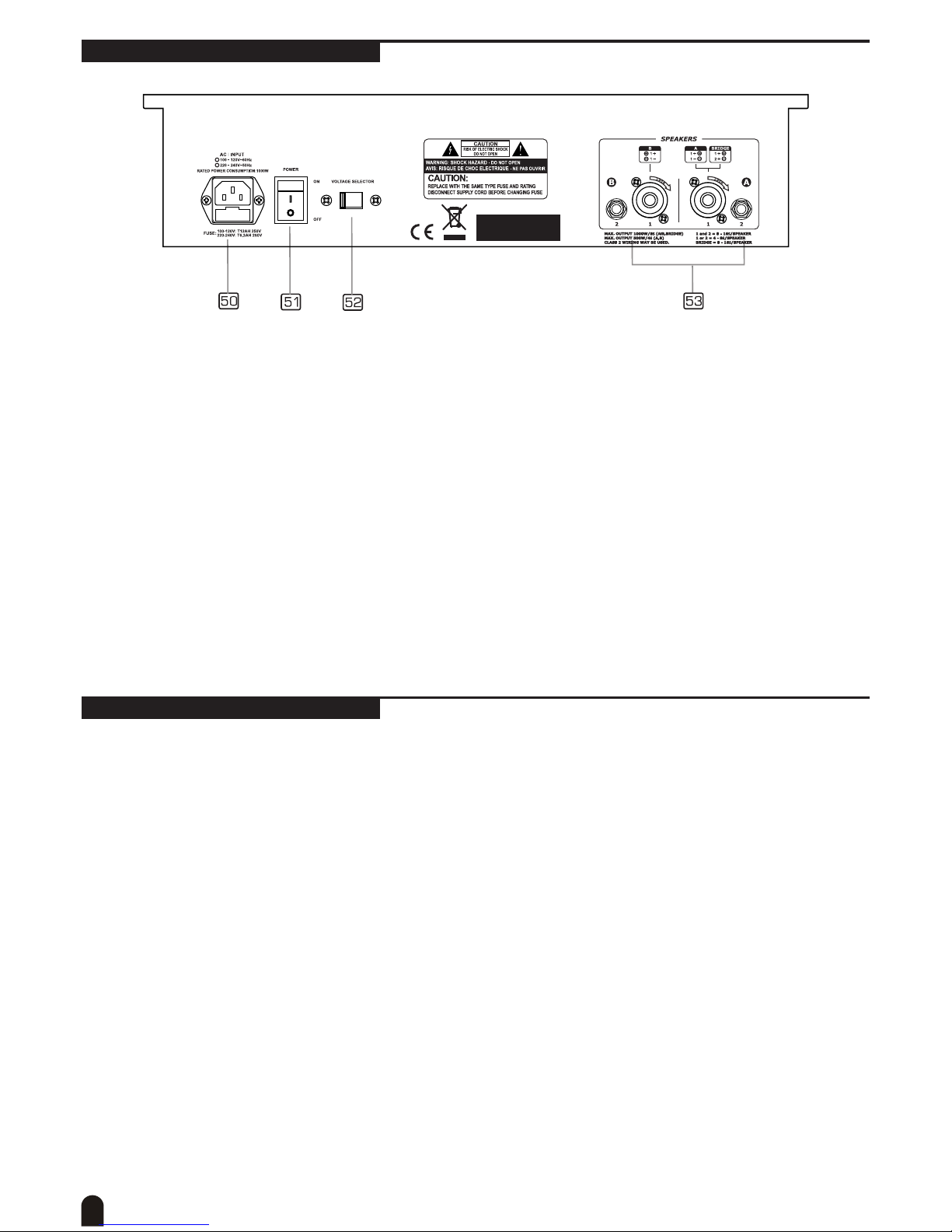
. . . on the rear Panel
50. ACInletwithFUSEHolder
Use it to connect your DPM 1122 to the main AC with the supplied AC cord. Please check the voltage
available in your country and how the voltage for your unit is congured before attempting to connect your
unit to the main AC.
51. POWERON/OFFSwitch
This switch is used to turn the main power ON and OFF.
52. VOLTAGESelector
There are two kinds of voltages for your operation. From this switch you can select the voltage at
100~120VAC or 220~240VAC. Always set this switch according to the voltage available in your country.
53. SPEAKERS Jacks
These jacks are used to connect speakers. They are congured with 4-way speakon connectors and 1/4”
phone jacks. You can determine the signal that is output to these jacks according to the setting of the
AMPLIFIER MODE select switch.
Note: In order to avoid damage to the built-in amplier, please pay attention to the allowed impedance of
the speaker. Very low load impedances may damage the amplier.
Installation and Connection
Ok, you have got to this point and you are now in the position to successfully operate your DPM 1122.
However, we advise you to read the following section carefully to be the real master of your mixer. Not paying
enough attention to the input signal level, the routing of the signal and the assignment of the signal will result
in unwanted distortion, a corrupted signal or no sound at all. So you should follow the following procedure for
every single channel:
1. Turn down all input and output gain controls.
2. Connect phantom powered microphones before switching on the +48 Volt phantom power switch.
3. Set the output level of your THE T.MIX DPM 1122 or the connected power amplier at no more than 75%.
4. Position EQ controls on middle position.
5. Position panoramic (PAN) control on centre position.
6. Increase the input gain properly for maintaining the good headroom and ideal dynamic range.
7. Depending on the actual application, turn slowly the input and output level controls for obtaining the
maximum gain before distortion.
8. Now repeat the same sequence for all input channels. The main LED meter could move up into the red
section. In this case you can adjust the overall output level through the main mix control.
13
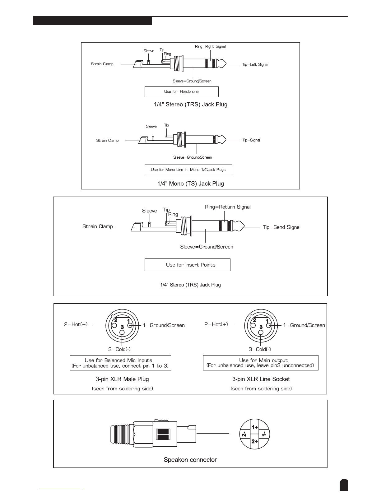
Audio Connections
You can connect unbalanced equipment to balanced inputs and outputs. Simply follow these schematics:
14
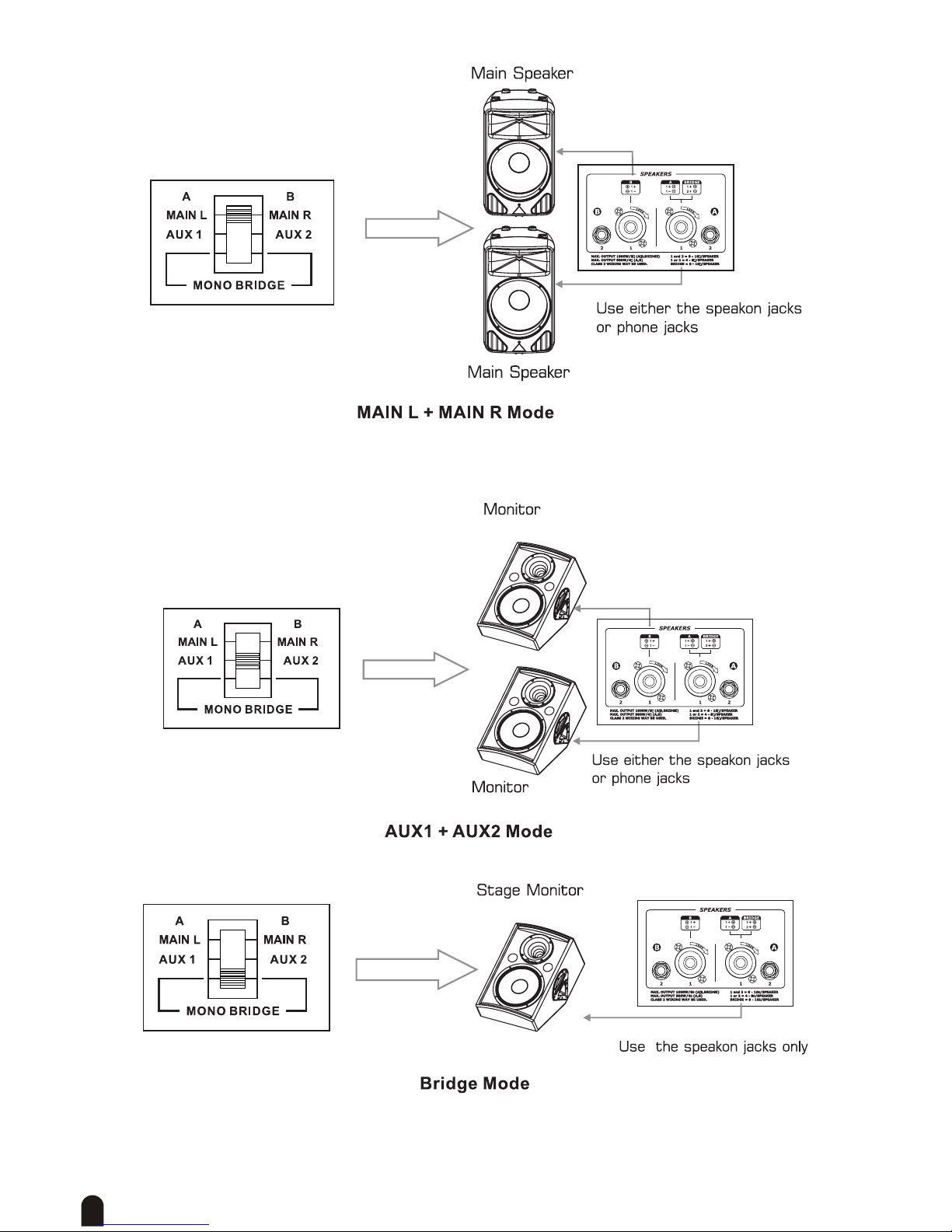
And now some tips how to use the AMPLIFIER MODE switch
This is the most common application. The built-in amplier drives two main speaker cabinets Left and Right.
The AMPLIFIER MODE is on MAIN L+MAIN R position.
With the AMPLIFIER MODE in AUX1+AUX2 position, the built-in amplier drives two monitor speakers.
With the AMPLIFIER MODE switch in BRIDGE position the two power ampliers in your DPM 1122 drive
together a single speaker cabinet with the sum of the power of the 2 amps. Usually this solution is used to
drive a single subwoofer or stage monitor and the main out output on the front panel are used to feed a pair of
powered speakers as mid-high units.
15
Preset List
16
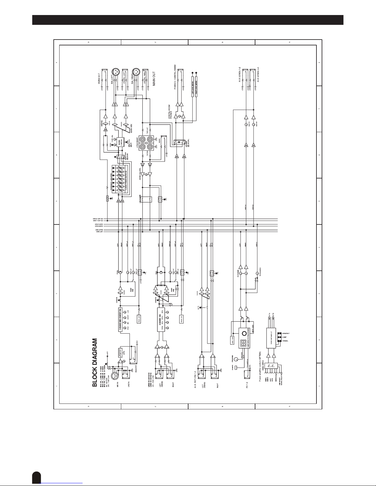
Block Diagram

17
Technical Specifications

18
Disposal
Neverthrowthedeviceintotheregularhouseholdwasteattheendofitsusefullife.
ThisproductissubjecttotheEuropeanDirective2002/96/EC.
Dispose of the device through an approved disposal centre or at your community waste facility.•
Observe the current existing regulations. In case of doubt contact your disposal facility.•
The packaging is certied via a dual system. Take all packaging materials to an environmentally •
friendly disposal facility in compliance with the local regulations.

19

© 2010
Musikhaus Thomann
Treppendorf 30 • 96138 Burgebrach • Germany
www.thomann.de
Table of contents


