TÜNKERS SDZ 40 F User manual

21.02.2019
Translation of the original Installation and operating instructions
TÜNKERS Maschinenbau GmbH
Installation and operating instructions
Retractable Locating and Expanding Pin SDZ 40 F
Handbuchart Installation and operating
instructions
Maschine Retractable Locating and
Expanding Pin SDZ 40 F
MaschinenNr nnn
MaschinenTyp Machine
Version 1. Draft -not released 2.
Draft -not released
KundeName TÜNKERS Maschinenbau
GmbH
KundeAdresse Am Rosenkothen 4-12
KundeOrt D-40880 Ratingen, Ger-
many
KundeTelefon +49 (0) 2102/4517-0
KundeLand Germany
KundeFax +49 (0) 2102/4517-9999
KundeEmail info@tuenkers.de
Erstelldatum 15/11/2018
Dateiname
MBA_Stiftziehzylinder_mit
_Spreizdorn_SDZ 40 F_EN
Zusatz1 (Retractable Locating and Expanding Pin
SDZ 40 F)
Zusatz2 (Pin drawing cylinder with spreading man-
drel SDZ 40 F)
Model year 2018
KundeWeb www.tuenkers.de
KEFunktion1 Clamping, holding, locking
and releasing of fixtures/components, e.g. on turn-
tables.
Copyright 2018
Hersteller TÜNKERS Maschinenbau
GmbH

Status: 21.02.2019
Translation of the original Installation and operating instructions nnn
TÜNKERS Maschinenbau GmbH
Copyright
This Installation and operating instructions is a document in accordance with the law against unfair com-
petition.
The copyright of which remains
TÜNKERS Maschinenbau GmbH
Am Rosenkothen 4-12
D-40880 Ratingen, Germany
Tel.: +49 (0) 2102/4517-0
Fax: +49 (0) 2102/4517-9999
Internet: www.tuenkers.dewww.tuenkers.de
This Installation and operating instructions is intended for the operator of the Machine and their staff. It
contains texts, pictures and drawings that without explicit approval from the TÜNKERS Maschinenbau
GmbH cannot be completely nor partially
▪copied,
▪distributed or
▪disclosed in any other way.
Permission is granted to the operator of the Machine for internal use.
© Copyright TÜNKERS Maschinenbau GmbH 2018

Table of contents
Page 3
Status: 21.02.2019
Translation of the original Installation and operating instructions nnn
TÜNKERS Maschinenbau GmbH
Table of contents
1General description ....................................................................................................... 4
1.1 Information about Installation and operating instructions...............................................4
1.2 Layout of the Installation and operating instructions .....................................................4
1.3 Use of the Installation and operating instructions..........................................................4
1.4 Obligations of the Operator ........................................................................................5
1.5 Training instructions..................................................................................................5
1.6 Requirements for staff...............................................................................................5
1.7 Dangers when operating the Machine ..........................................................................6
1.8 Intended use............................................................................................................6
1.9 Reasonably foreseeable misuse ..................................................................................7
1.10 Warranty claims and liability ......................................................................................7
2Safety instructions ........................................................................................................ 8
2.1 Safety symbols in this Installation and operating instructions .........................................8
2.2 General safety instructions.........................................................................................8
2.3 Safety instructions for operation .................................................................................9
2.4 Safety instructions for setup, maintenance, servicing, repair and troubleshooting ...........10
3Technical data ............................................................................................................. 12
3.1 Complete Machine................................................................................................... 12
3.2 Pneumatic equipment.............................................................................................. 12
3.3 Electrical equipment................................................................................................12
4Setup and function ...................................................................................................... 13
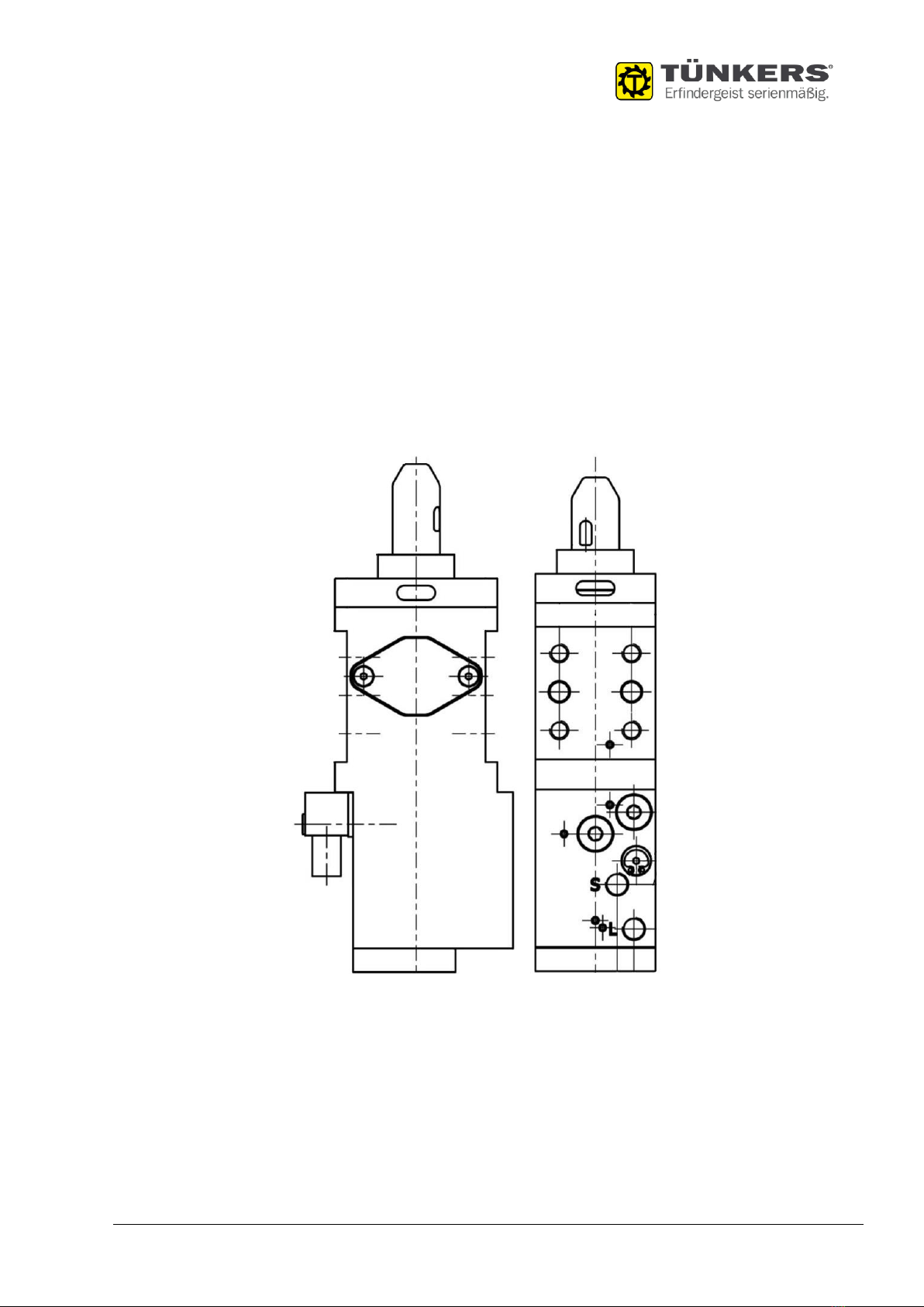
4.1 Overview Pin drawing cylinder with spreading mandrel SDZ 40 F ..................................13
5Transport, Assembly and Commissioning .................................................................... 14
5.1 Assembly...............................................................................................................14
5.2 Initial Start-up........................................................................................................15
6Operation .................................................................................................................... 15
6.1 Safety instructions ..................................................................................................15
6.2 Operating the Pin drawing cylinder with spreading mandrel SDZ 40 F............................15
6.3 Basic checks before and during operation ..................................................................15
7Maintenance ................................................................................................................ 16
7.1 Safety instructions ..................................................................................................16
7.2 Maintenance and repair work.................................................................................... 16
7.3 Maintenance schedule .............................................................................................16
8Troubleshooting .......................................................................................................... 17
8.1 Safety instructions ..................................................................................................17
9Appendix ..................................................................................................................... 18
9.1 Declaration of installation ........................................................................................18

General description
Chapter 1
Information about Installation and operating instructions
Page 4
Status: 21.02.2019
Translation of the original Installation and operating instructions nnn
TÜNKERS Maschinenbau GmbH
1General description
This chapter contains notes on this Installation and operating instructions, along with general safety
instructions for handling the Retractable Locating and Expanding Pin SDZ 40 F.
In the following sections, the partially completed machine Retractable Locating and Expanding Pin SDZ
40 F is also referred to as the Machine.
1.1 Information about Installation and operating instructions
This Installation and operating instructions is an key component of the user documentation for the Ma-
chine. Follow all instructions, data, and requirements in the Installation and operating instructions. The
Installation and operating instructions will help you to operate the Machine safely, and with a high avail-
ability.
We reserve the right to make technical changes designed to improve the Machine described in the In-
stallation and operating instructions.
1.2 Layout of the Installation and operating instructions
Safety-relevant instructions are identified by the appropriate symbols.
Listings
Listings of features in any order or an order that need not be strictly maintained are marked with a bullet.
Example:
▪Property A
▪Property B
Sub-property of property B
Order
Steps that must be performed in the specified order are enumerated and the results of the steps are
shown in italics.
Example:
1. Step 1 to be performed
Result of step 1
2. Step 2 to be performed
2.1 Sub-step of step 2 to be performed
1.3 Use of the Installation and operating instructions
This Installation and operating instructions helps you to familiarise yourself with the Machine and use it
as intended.
The Installation and operating instructions must be supplemented due to existing national directives
concerning accident prevention and environmental protection.
Ensure that the Installation and operating instructions is always available at the operation site of the
Machine and is in a legible condition.
The Installation and operating instructions must be read and applied by all persons commissioned to work
with/on the Machine, e.g.: operating including setting-up, fault repair, care, disposal of operational and
auxiliary materials, repairs (maintenance, servicing) and / or transportation.
In addition to the Installation and operating instructions and the binding regulations for accident preven-
tion applicable in the country and site of implementation, the approved industry-specific rules for safety
and professional work must be complied with.

Status: 13.08.2019
Translation of the original Installation and operating instructions nnn
TÜNKERS Maschinenbau GmbH
1.4 Obligations of the Operator
The operator is obliged to only allow persons to work on the Machine , who
▪are familiar with the basic requirements concerning work safety and accident prevention, and are
trained in the operation of the Machine .
▪have read and understood the safety instructions and warning instructions in this Installation and
operating instructions and have confirmed this with their signature.
▪have been trained or instructed and whose responsibilities for operation, setting up, maintenance
and repairs have been clearly defined.
▪are regularly instructed in complications, hazards, and other particular rules of conduct.
The operator is obliged to:
▪observe and instruct staff on the legal and other obligatory regulations on accident prevention,
environmental protection and handling of dangerous goods in addition to the Installation and op-
erating instructions .
▪provide protective equipment.
▪establish the responsibility of the Machine operator, to allow the Machine operator to reject unsafe
third party instructions.
▪check safety-aware work of staff at regular intervals.
▪follow legal requirements and rules at the site of the Machine.
1.5 Training instructions
Only deploy trained or instructed staff. Clearly define staff responsibilities for operation, setting-up,
maintenance and repairs.
While working on or with the machine, staff who have not yet completed training, or staff working on the
machine in the course of an apprenticeship, must be accompanied and supervised by an experienced
member of staff who is familiar with the Machine at all times.
1.6 Requirements for staff
Before commencing work, all persons tasked with working on the Machine must:
▪follow the basic instructions concerning work safety and accident prevention.
▪read the safety and warning instructions in this Installation and operating instructions and confirm
that they have understood them with their signature.
▪use personal/ workplace-related protective clothing and auxiliary materials that serve work safety
or while working, provided that this is necessary for safety related reasons.
▪comply with specifications of competence.
For example, work on the electrical or pneumatic device of the Machine can only be performed by a
qualified electrician, or by staff who have received appropriate training, monitored by a qualified electri-
cian as per the current technical rules.
Unauthorised persons are not permitted access.

Status: 13.08.2019
Translation of the original Installation and operating instructions nnn
TÜNKERS Maschinenbau GmbH
1.7 Dangers when operating the Machine
The Machine has been constructed according to the state of the art and in line with recognised safety
regulations. In spite of this, hazards to life and limb of the users or to third parties, or impairments to
the Machine and other capital assets can arise from its use.
Only use the Machine when in a safe and perfect state and for the intended use.
WARNING
Observe safety instructions!
▪Only operate the Machine if the protective devices and safety devices are inte-
grated into the complete system, for example, separating protective devices or
emergency stop systems required for operating the Machine are in place and
functional.
▪Immediately eliminate any faults that could impair safety.
▪Observe the residual risks and dangers in Chapter 2 “Safety instructions".
1.8 Intended use
The Machine is designed exclusively for holding a component on the retractable/extensible centring man-
drel and clamping the component with the retractable/extensible clamping jaws.
The Machine must be operated exclusively within the performance limits stated in Chapter 3 "Technical
data".
Any other use, or any use beyond this scope shall be regarded as misuse and is unintended; TÜNKERS
Maschinenbau GmbH company shall not be liable for any damage resulting from unintended use.
The partially completed Machine must not be operated until it has been installed in a Machine that com-
plies with the provisions of the pertinent Machinery Directive.
The incomplete Machine must be incorporated into a complete machine. The manufacturer/operating
company of the complete machine must ensure that the partially completed Machine is integrated into
the emergency stop circuits of the complete machine and into the control system, and must create the
appropriate operating modes.
Access to the partially completed Machine must be secured by the manufacturer/operating company of
the complete machine and regulated by the operating company, e.g. protective perimeter with interlocked
safety doors.
Operating functions must be designed to reflect the operating mode, e.g., they must be disabled when a
safety door is open and the safety zone can be entered.
Mechanical hazards resulting from the integration of the incomplete Machine into the overall machine
must be assessed and, if necessary, safeguarded by the manufacturer/operator of the complete machine
(e.g., by means of isolating safety devices, local connection of the operator via enabling switches, etc.).
The manufacturer/operator of the complete machine in which the partially completed Machine is installed
is responsible for ensuring that it can absorb all static/dynamic forces of the complete machine.
Intended use also includes:
▪observing all information and directives in the operating instructions and all applicable documents.
▪observing the mandatory service and maintenance intervals, or the service and maintenance in-
tervals specified in the instruction manual and applicable documentation.

Status: 13.08.2019
Translation of the original Installation and operating instructions nnn
TÜNKERS Maschinenbau GmbH
1.9 Reasonably foreseeable misuse
The following, in particular, are considered as reasonably foreseeable misuse:
▪Use of components that do not comply with the product specification.
▪Use of the Machine for other purposes.
▪Operating the Machine with bridged safety devices.
▪Operating the Machine with incomplete protection.
▪Acknowledging safety devices while a person is in the protected area.
▪Operating, maintaining and repairing the Machine by non-authorised and non-instructed persons.
▪Operating the Machine in an area with a risk of explosion.
1.10 Warranty claims and liability
Our "General Terms of Sale and Delivery" always apply. These are available to the operator of the Machine
on the conclusion of the contract at the latest.
Warranty and liability claims in the case of personal injury and material damage are excluded if they are
due to one or more of the following causes:
▪Unintended use
▪Incorrect assembly, commissioning, operating, and maintenance.
▪Operating the Machine with defective safety equipment, or without appropriate safety equipment
or with non-functional safety protective devices.
▪Failure to follow the instructions for transportation, storage, assembly, commissioning, operation,
maintenance and setting-up in the Installation and operating instructions,
▪Unauthorised physical/structural changes.
▪Inadequate monitoring of Machine components that are subject to wear and tear..
▪Improper repair works.
▪Disasters caused by foreign objects or an Act of God.
▪Vandalism.

Status: 13.08.2019
Translation of the original Installation and operating instructions nnn
TÜNKERS Maschinenbau GmbH
2Safety instructions
2.1 Safety symbols in this Installation and operating instructions
DANGER
"DANGER" identifies an immediate threat of danger which can lead to severe injury
or death.
WARNING
"WARNING" identifies a potentially dangerous situation which can lead to severe in-
jury or death.
CAUTION
“CAUTION" identifies a potentially dangerous situation which could lead to minor in-
jury.
NOTE
"NOTE" identifies a potentially dangerous situation that can lead to material and en-
vironmental damage.
This signal word is also used for application instructions and other useful information.
2.2 General safety instructions
WARNING
Risk to persons and the Machine!
▪Maintain all safety and hazard instructions at and on the Machine in a complete
and legible condition!
▪Avoid any unsafe methods of working.
▪Keep the Installation and operating instructions available at the machine site at
all times.
▪Stop the Machine immediately and report the fault to the responsible depart-
ment/person when safety-relevant modifications are made to the machine line
or the operating behaviour of the Machine changes.
▪Follow the applicable regulations for occupational safety and health protection
(DGUV (German Statutory Accident Insurance) regulations).
▪Do not arbitrarily modify the Machine.

Status: 13.08.2019
Translation of the original Installation and operating instructions nnn
TÜNKERS Maschinenbau GmbH
CAUTION
Risk of injury!
▪Use personal protective clothing, safety shoes, ear protection and safety gloves.
▪Use prescribed safety gear!
2.3 Safety instructions for operation
WARNING
Risk of injury due to clamping movement!
Danger of crushing in case of reaching in between the component and extended
clamping jaws when clamping the component.
▪Do not reach in between the component and the extended clamping jaws.
▪Before actuating or initiating individual movements, make sure that no one will
be endangered by these actions.
WARNING
Danger due to the entire machine moving!
The Machine is mounted on, e.g., a turntable. Unintended movement of the turnta-
ble/the complete machine can result in serious injury to personnel and damage to
the Machine.
▪Observe the operating instructions for the complete machine.
▪Observe the movements of the complete machine from a safe place.
▪If several persons are working in a danger zone, there must be constant eye
contact between all of them.
WARNING
Improper use of the Machine!
▪Use the Machine in line with its intended purpose.
▪Use the Machine in a technically perfect, operationally ready and functionally
reliable state.
▪Have any damage to the Machine professionally repaired, before putting the
Machine into operation.
▪Check the Machine for damage before starting work.

Status: 13.08.2019
Translation of the original Installation and operating instructions nnn
TÜNKERS Maschinenbau GmbH
WARNING
Improper use of the Machine!
▪Only qualified and authorised staff are permitted to operate the Machine.
▪Familiarise yourself with the Machine.
▪Clearly establish responsibilities and work areas.
▪Be aware of all potential dangers on the Machine.
CAUTION
Danger of injury in the event of damage to the pneumatic system!
Media under high pressure unexpectedly develop high forces and can cause injuries.
▪In case of damage to the pneumatic equipment, switch off the Machine and im-
mediately inform the appropriate department/person.
▪Immediately repair any damage.
▪All work on pneumatic equipment can only be carried out by authorised and
skilled professionals.
2.4 Safety instructions for setup, maintenance, servicing, repair and trou-
bleshooting
WARNING
Danger to persons and the Machine!
▪Only authorised specialists may set up and maintain the Machine and remedy
malfunctions.
▪Familiarise yourself with individual maintenance and repair instructions before
carrying out work.
▪Cordon off the area for set-up work, servicing, maintenance and fault repair with
a large parameter, as required.
WARNING
Risk of accidents!
▪Cordon off the maintenance and repair area with a large safety perimeter as
required.
▪Make sure that there is no one in the danger area before switching on the Ma-
chine .
▪Be careful and observant in the entire working area of the Machine and the
complete system.
WARNING
Danger due to unexpected restart!
▪Deenergise and depressurise the Machine during adjustment, maintenance and
repair works and lock to prevent an unexpected restart.
▪Post a warning sign on the control unit, stating that the Machine must not be
operated.

Status: 13.08.2019
Translation of the original Installation and operating instructions nnn
TÜNKERS Maschinenbau GmbH
CAUTION
Danger due to improper work on the Machine!
▪The specified adjustment, maintenance and servicing work at the required in-
tervals is carried out by qualified personnel.
▪Clean loosened connections and screw connections.
▪Tighten screw connections to the corresponding tightening torque.
▪Regularly check all screw connections.
▪Follow the maintenance schedules provided by third-party manufacturers.
NOTE
Material damage due to improper cleaning!
The wrong cleaning agents and methods can lead to serious material damage on the
machine.
▪Follow the manufacturer's specifications on system components and cleaning
agents.
NOTE
Pollution!
▪Dispose of replaced parts, operating fluids and auxiliary materials in a safe and
environmentally friendly manner.

Status: 13.08.2019
Translation of the original Installation and operating instructions nnn
TÜNKERS Maschinenbau GmbH
3Technical data
3.1 Complete Machine
Pneumatic equipment
Designation
Retractable Locating and Expanding Pin SDZ 40 F
Year of construction:
2018
Emission sound pressure level (LpAd):
<70 dB(A)
Weight:
2 kg
Dimensions (L x W x H):
approx. 88mm x 50mm x 213mm
Stroke:
10 mm
Tensile force:
1000 N
Pressing force:
850 N
Clamping range:
0 - 6 mm
Tolerance pin bore:
± 0.02 mm
Tolerance threaded hole:
± 0.1 mm
3.2 Pneumatic equipment
Pneumatic equipment
Pneumatic pressure:
6 bar
External connection:
Dry, oil-free and cleaned
3.3 Electrical equipment
Electrical equipment
Operating voltage sensors:
01.10.1930 V DC

Status: 13.08.2019
Translation of the original Installation and operating instructions nnn
TÜNKERS Maschinenbau GmbH
4Setup and function
4.1 Overview Retractable Locating and Expanding Pin SDZ 40 F
The Machine is used to pick up and centre a component on the centring mandrel and to clamp the com-
ponent with the clamping jaws.
When the centring mandrel (a) extends, the clamping jaws (b) retract. The operator places the compo-
nent to be clamped on the support (c) via the centring mandrel. When the centring mandrel (a) is re-
tracted, the clamping jaws (b) extend and clamp the component against the support.
Fig. 4.1-1: Overview Retractable Locating and Expanding Pin SDZ 40 F
Pos.
Designation
Description
a
Centring mandrel
Extends/retracts. Centres the bore of the component.
b
Clamping jaws
Retract/extend. Clamp the component.
c
Support
Receives the component.
d
Threaded holes
Fasten the pin drawing cylinder.
e
Sensor set
Monitors the position of the centring mandrel and the clamping jaws.
f
Release
Deblocks via a pushbutton, which depressurises the system.
g
“Clamp” connection
Pneumatic connection: Retracts centring pin and extends clamping jaws.
h
“Release” connection
Pneumatic connection: Extends the centring pin and retracts the clamping
jaws.
a
b
d
d
e
f
d
c
h
g

Status: 13.08.2019
Translation of the original Installation and operating instructions nnn
TÜNKERS Maschinenbau GmbH
5Transport, Assembly and Commissioning
WARNING
Danger to persons and the Machine!
▪Only qualified personnel should be tasked with assembly and commissioning.
▪Keep unauthorised persons away from the work.
▪Use personal protection equipment.
▪The operator must always have a line of sight to the danger area.
▪During assembly, conversion, maintenance and adjustment work, disconnect the
energy supplies and make sure there is no residual energy in the system.
5.1 Assembly
Requirement:
▪The system on which the Machine is to be mounted must be deenergised and depressurised.
▪Machine is ready for assembly.
▪Bolting material is available.
Work steps:
Fig. 5-1: Assembling the Machine
NOTE
Material damage due to incorrect screw lengths!
Screws that are too long prevent correct fastening.
1. Mount the Machine with four socket head bolts M8 x 1.25 to the holes (b) of the front or rear
shoulder surface.
2. Connect the compressed air supply between the pneumatic control and the connections (d, c).
3. Connect the sensor set to the controller.
The use of external throttle valves is recommended for fine adjustment of the clamping action
speed.
The Machine is ready for use.
d
c
a

Status: 13.08.2019
Translation of the original Installation and operating instructions nnn
TÜNKERS Maschinenbau GmbH
5.2 Initial Start-up
Employees of the TÜNKERS Maschinenbau GmbH, the system manufacturer, or the operating company
establish the connection according to the circuit diagram/pneumatic diagram and the setup during initial
start-up.
6Operation
The Machine must only be used according to its intended use (see chapter 1.8 "Intended use"). Specific
requirements and safety instructions apply for the different operating modes of the Machine.
The Machine is run in the following operating modes:
▪Automatic mode
▪Manual mode (set-up mode)
The operator/manufacturer of the complete system is responsible for executing the operating modes.
The work involved with the operation, tooling, maintenance, and fault repair can be assigned to these
operating modes.
6.1 Safety instructions
WARNING
Observe safety instructions!
▪Observe the safety instructions in Chapter 2 "Safety instructions" and in particu-
lar Chapter 2.2 "General safety instructions".
6.2 Operating the Retractable Locating and Expanding Pin SDZ 40 F.
The Machine doesn’t have any controls. The Machine is operated via the control of the complete system,
in which the Machine is used.
NOTE
For information on operation, observe the operating manual of the complete system.
6.3 Basic checks before and during operation
Familiarise yourself with your work environment before starting work. Externally check (visually) the
Machine for visible defects at least once per shift. Before starting work, the service and maintenance
intervals must be followed in line with the maintenance schedule.
Before switching on the Machine and during operation, monitor the Machine area for anomalies at all
times. The following features may indicate irregularities the Machine are switched on:
▪increased noise, noise irregularly occurring/unusual noises.
▪unusual smell
▪leaks in the pneumatic system.
▪reduced performance during operations
▪incorrectly positioned
Shut down the Machine immediately upon the first signs of any of the above issues. Inform maintenance
staff immediately for an accurate assessment of the technical status.
Maintenance staff must then decide if operation can continue without limiting the functionality of the
Machine. If a failure is expected due to damage, perform repairs immediately.

Status: 13.08.2019
Translation of the original Installation and operating instructions nnn
TÜNKERS Maschinenbau GmbH
7Maintenance
7.1 Safety instructions
DANGER
Follow the safety instructions!
▪Follow the safety instructions in chapter 2 "Safety instructions" and in particu-
lar chapter 2.2 "General safety instructions".
7.2 Maintenance and repair work
The Machine is designed for a low-maintenance operation. The care, maintenance and repair work de-
scribed in this chapter are required to maintain a problem-free implementation of the Machine as in-
tended. Regular care and maintenance extend the service life and increase the usability.
Only use materials, consumables and auxiliary substances that have been recommended by the manu-
facturer. Recommended lubricants are specified when required. Never mix lubricants.
NOTE
Carry out special maintenance work in accordance with the maintenance plans of
the third party manufacturers!
Perform all maintenance work listed below at the appropriate intervals.
7.3 Maintenance schedule
NOTE
The Retractable Locating and Expanding Pin SDZ 40 F is equipped with low-mainte-
nance bearings and guides. Due to the closed design of the Retractable Locating
and Expanding Pin SDZ 40 F, special maintenance is not required.
NOTE
Possible damage due to improper cleaning!
Cleaning with steam jet cleaner or dry ice will damage the Retractable Locating and
Expanding Pin SDZ 40 F.

Status: 13.08.2019
Translation of the original Installation and operating instructions nnn
TÜNKERS Maschinenbau GmbH
8Troubleshooting
8.1 Safety instructions
DANGER
Observe safety instructions!
▪Observe the safety instructions in Chapter 2 "Safety instructions" and in partic-
ular Chapter 2.2 "General safety instructions".
Machine does not clamp/release
Possible cause
Repair measures
Errors/damages in the air supply
Check the air supply.
Falls below the minimum oil pressure
Check the operating pressure.
Clamping segments worn
Replace the clamping segments as part of a complete overhaul.
Clamping segments are difficult to move
Blow out clamping segments with compressed air, if necessary
grease with Molykote BR2 Plus.
Spreading and centring mandrel worn or
deformed
Replace spreading and centring mandrel.
Sensor set does not detect positions
Possible cause
Repair measures
Proximity switch does not switch
Proximity switch is incorrectly positioned Adjust the position
Cabling, connections are defective or loose.
Proximity switch is defective. Replace proximity switch
Proximity switch at bottom not switching
Set proximity switch to sheet thickness to be clamped.
Clamping jaws extending too slowly
Spreading and centring mandrel worn.
Clamping jaws extending too slowly
Set the speed via external compressed air throttles.
Spreading and centring mandrel worn.
Replace spreading and centring mandrel.

Status: 13.08.2019
Translation of the original Installation and operating instructions nnn
TÜNKERS Maschinenbau GmbH
9Appendix
9.1 Declaration of installation
Declaration of incorporation
In line with the Machinery Directive 2006/42/EC, Appendix II A
The manufacturer
TÜNKERS Maschinenbau GmbH
Am Rosenkothen 4-12
D-40880 Ratingen, Germany
+49 (0) 2102/4517-0
of the partially completed machine
hereby declares:
General designation
Retractable Locating and Expanding Pin SDZ 40 F
Function
Clamping, holding, locking and releasing of fixtures/com-
ponents, e.g. on turntables.
Type designation
Retractable Locating and Expanding Pin SDZ 40 F
Serial number
-
Product name
Retractable Locating and Expanding Pin SDZ 40 F
Year of construction
2018
the following basic health and safety requirements in line with appendix I of the machine directive
have been applied and adhered to:
Annex I, Article 1.1.2, 1.1.3, 1.1.5, 1.3.1, 1.3.2, 1.3.3, 1.3.4, 1.5.4, 1.5.8, 1.6.1, 1.6.3, 1.7.1, 1.7.3
und 1.7.4
The partially completed machine also complies with all provisions of the EMC Directive 2014/30/EU.
Specific technical documentation was created in line with Annex VII Part B.
All relevant information about the partially completed machine will be provided on reasoned request
by the appropriate national authority.
Commissioning is prohibited until it has been established that - where applicable - the machine into
which the partially completed machine above is to be installed complies with the provisions of the
Machinery Directive 2006/42/EC.
Authorised representative for composing the technical documentation:
TÜNKERS Maschinenbau GmbH, Am Rosenkothen 4-12, D-40880 Ratingen, Germany, Tel.: +49 (0)
2102/4517-0
Ratingen
Place/date:
Olaf Tünkers
Managing Director
Table of contents