Taco Neptune Tele-Shade User manual

Neptune Tele-Shade
Installation Instructions
Neptune Tele-Shade
T34-2001VEL-1

Contents
Qty Description
2 Front leg assemblies (with stainless steel pull pin)
2 Rear leg assemblies (with stainless steel push pin)
1 Port ring side
1 Starboard ring side
3 Ring cross braces 58-1/4"
2 Ring joiners 45-1/2"
6 Tubingjoinerttings
4 1-1/4" x 1/2” joiner pins
4 Tubing clamps
1 Porttopconsolemount(identiedonundersideofmount)
1 Starboardtopconsolemount(identiedonbottomofmount)
1 Portbottomconsolemount(identiedonbottomofmount)
1 Starboardbottomconsolemount(identiedonbottomofmount)
8 1/4” stainless steel lag bolts and washers
6 Black tubing plugs
1 Canvas with lacing
2 Stainless steel locking pins
6 1-1/2” cap screws
Installing the Console Mounts
1) Placethedrillingtemplateontheportsideoftheconsole,
aligningthedottedlinewiththetopedgeoftheconsole
(Figure 1).
2) The5°linesmarkedportaretherelativedrillingpositionsfor
the top and bottom mounts.
3) Theoverallwidthofthemountextends1"totheleftandright
ofthecenterofthedrillhole.(Youmayhavetorepositionyour
template to prevent the
mountfromextending
over the side edges
oftheconsole).
4) Drill the top mounting
holes with a 5/16" drill.
Make sure the mount is
level and that there are no
obstructions behind the
mount (Figure 2).
5) The lower mount must be at least 15" below the top mount. Use the same
technique as in Step 2.
Note: The top mount is larger to accommodate the draft of the console (consoles are narrower at the top).
It is imperative that the legs are vertical left to right.
Recommended Tools:
Level
Tape measure
Straight edge
Masking tape
Allen wrench
Drill
Figure 1 Figure 2
FrontLegAssembly
RearLegAssembly
Starboard Ring
Port Ring
Ring Cross Brace
Ring Joiners
Tubing Joiner Fittings
Joiner Pins
1-1/4" Tubing Caps
Port Top Mount
Port Bottom Mount
Starboard Bottom Mount
Starboard Top Mount
Tube Clamp

1) Install the port mounts. Remember the legs rake toward the stern, the
mounts are machined to allow the leg to t in at the correct angle.
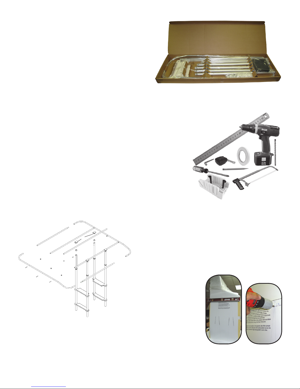
It is imperative that the legs are vertical left to right (Figure 3).
Tip: To achieve a tighter t to the console, the console mounts can be cut down
using a table saw with a standard wood blade.
2) Usingthe1/4"lagboltsandwashers,attachthemountsthroughtheinsideofthe
console.Iftheconsoleislessthan1/2"thickyouwillneedabackingplateto
preventtheconsolefromcracking.Theconsolespacersallowforadjustmenton
the mount to keep the legs vertical.
3) Slidethelegsthroughthemounts.Thefrontleghasapullpinlockandrearlegs
has a spring loaded locking pin. Once the legs are installed and vertical
(port to starboard) tighten the mounting bolts.
4) Therearesetscrewsinthefrontandbackofthemounts.Tightenthese
gentlyagainstthetube.Donotovertightenasyouwilldeformthetubeand
the legs will bind.
Assembling the Legs
1) Insertthe1/2"joinerpinscompletelythroughthetubeatthetopoftheupperleg.Thethreadedholeinthepinmustbe
parallelwiththeleg.Makesurethepinisushwiththesideofthetube(Figure4).
2) Place the 4 tubing caps over the 1-1/4" tube. These caps hold the joiner pins in place (Figure 5).
3) Make sure the legs are in the locked position (the pull pin is in place and the spring pins are snapped into the locking holes).
4) RemovetheAllenboltsthatholdtheclamptogether,andremovetherubberinerttoallowaccesstothe5/16"
bolt in the clamp.
5) Theclamptsoverthetubingcapandtheboltthreadsintothejoinerpin.Gentlytightenthescrewsothattheclamp
can still turn on the tube (Figure 6).
6) Takeoneofthecrossbracesandlayitinthesaddleoftheclamp,thiswillaligntheclamps.Whentheclampsare
aligned,tightenthe5/16"screwsecurelytopreventtheclampsfromturning(Figure7).
Intalling the Console Mounts (Continued)
Figure 3
Figure 4 Figure 5 Figure 6 Figure 7

Assembling the Ring
1) Pass the 2" screws through the larger diameter holes in the ring sides. There are 3 holes in each side ring.
2) Placethetubejoinerttingsoverthethreadsofthe2"screwsandgentlythreadthemin.Do Not Tighten Yet!
3) Pushtheringcrossbracesoverthejoinertubettingsononeoftheringsidestillthetubesbottomoutonthetting.
4) Tightenthe2"screwstoexpandthettinglockingthetubeinplace.Dothisforthe2additionalcrossbraces.
5) Insertthefrontandrearringjoinersintotheringside.
6) Usingthesameprocedureasinstep3,attachtheoppositeringsidetothecrossbracesandfrontandrearjoiners.
Tightenallboltsrmly.
7) Note: Their may be a space between the edge of the front and rear joiner and the ring sides. This will disappear
when the canvas is strung tight.
8) Installthe6blackplugsintotheboltholes,tappingtheplugsinlightlywithahammer.
Installing the Ring
1) Install the rubber insets into the clamps.
2) Placethefront2crossbarsintotheclampsaddles(Figure8).
3) Usingatapemeasurecentertheringinthesaddlelefttoright.
4) Install the clamp cover and tighten.
Canvas Top
1) Placethecanvasoverthetopoftheringandcenterit.
2) Tieoffthelacingtothemiddleofthesideringandbeginlacingthecanvas.
3) Pass the lacing through the grommet around the tube and back through
thesamesideofthegrommet(Figure9).
4) Bringthelacingdowntheundersideofthecanvasandupthroughthe
next grommet hole.
5) Once2sidesarecompleted,thethirdsidecanbepulledtighttodraw
the ring together.
6) Onceyoureachthelastgrommet,tieoffthelacingwithseveralwrapsaround
the tubing and square knot it to the grommet.
Testing
1) Releasethepullpinsinthefrontlegs.
2) Squeezetherearlegreleasepinsandliftthetopbythering.
3) Makesurethetopworksfreelyandlocksintoall3position.
TACOmarine.com
info@TACOmarine.com
Tech Support: 800-653-8567
INSTRUC-T34-2001VEL1
Figure 8
Figure 9
Table of contents
Popular Tent manuals by other brands

Weka
Weka 612.3260.30.00 ASSEMBLY, USER AND MAINTENANCE INSTRUCTIONS

DARCHE
DARCHE T050801200A instruction manual

SuperBox
SuperBox Evolution Assembly instructions

Kathmandu
Kathmandu Bora v2 instruction manual

Coleman
Coleman PUP Tent 9556-406K installation instructions

Coleman
Coleman Instant shelter Super Light Setup instructions