TAEHA PCP-005 Series User manual

PCP-005/015/050/150/500/1000 Rev 1.1
2021/02/03 1/45 Copyright ©2021 by TAEHA CORP. All Rights Reserved
PRO-PUMP SYSTEM
PCP-005/015/050/150/500/1000 Series
Operation Manual

PCP-005/015/050/150/500/1000 Rev 1.1
2021/02/03 2/45 Copyright ©2021 by TAEHA CORP. All Rights Reserved
Contents
1 General Information...................................................................................................................................................... 4
1.1 General Information...................................................................................................................................................... 4
1.2 Warranty............................................................................................................................................................................. 4
1.3 Technical Support .......................................................................................................................................................... 4
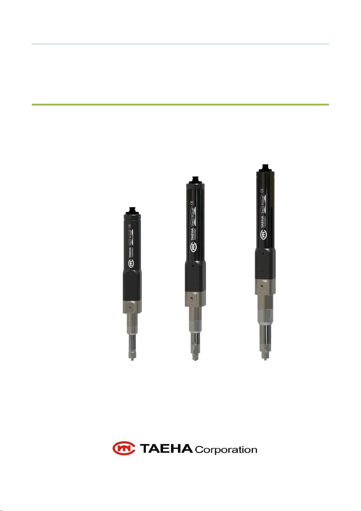
2 Pro Pump System (PCP) Feature............................................................................................................................. 5
2.1 Pro Pump System........................................................................................................................................................... 5
2.2 Pro Pump System Feature ......................................................................................................................................... 5
2.3 Pro Pump Feature & Specification ........................................................................................................................ 6
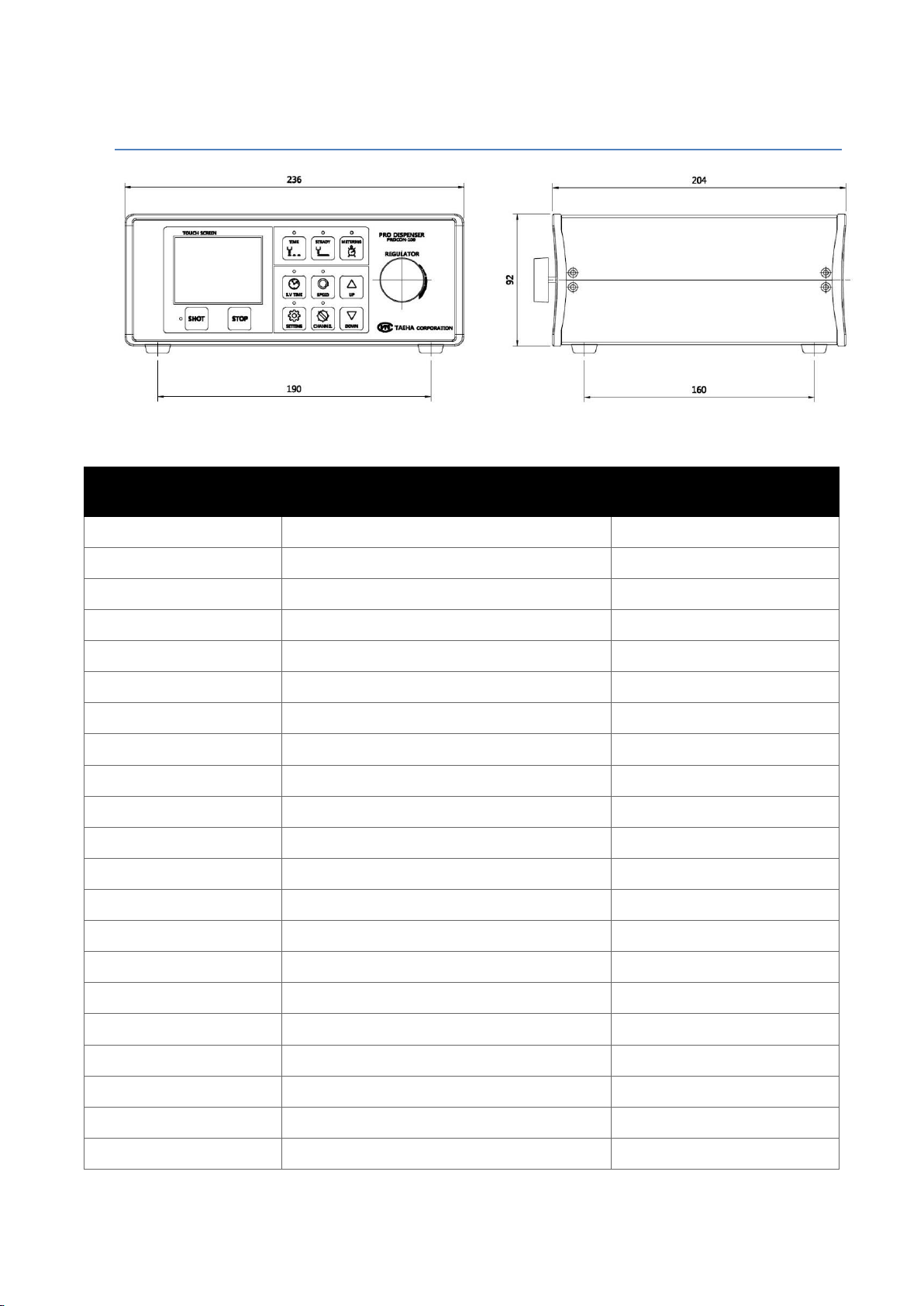
2.4 Pro Pump Controller Feature & Specification .................................................................................................. 8
2.5 PCP(Standard) System.................................................................................................................................................. 9
2.6 PCPM (Module Type) System.................................................................................................................................10
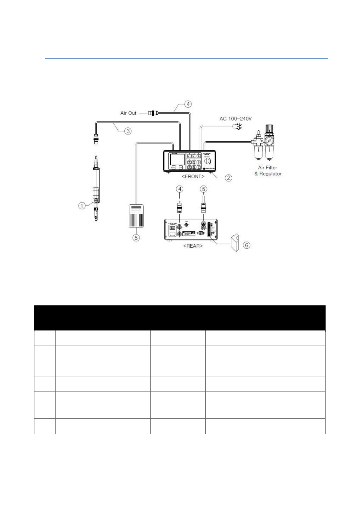
3 Name of each part ......................................................................................................................................................11
4 Pro Pump Operation ..................................................................................................................................................12
4.1 Precautions on Use and Assembly ......................................................................................................................12
4.2 Pro Pump Ready to Use ...........................................................................................................................................13
5 Pro Pump Disassemble..............................................................................................................................................14
5.1 PCP-005/015/050 Disassemble..............................................................................................................................14
5.2 PCP-150/500 Disassemble .......................................................................................................................................21
5.3 PCP-1000 Disassemble ..............................................................................................................................................28
6 Pro Pump Partlist .........................................................................................................................................................36
6.1 PCP-005 Partlist ............................................................................................................................................................36
6.2 PCP-015 Partlist ............................................................................................................................................................37
6.3 PCP-050 Partlist ............................................................................................................................................................38
6.4 PCP-150 Partlist ............................................................................................................................................................39
6.5 PCP-500 Partlist ............................................................................................................................................................40

PCP-005/015/050/150/500/1000 Rev 1.1
2021/02/03 3/45 Copyright ©2021 by TAEHA CORP. All Rights Reserved
6.6 PCP-1000 Partlist..........................................................................................................................................................41
7 Maintenance ...................................................................................................................................................................42
7.1 Alarm Display and Action ........................................................................................................................................43
7.2 Inspection and Measures .........................................................................................................................................44
7.3 Trouble Shooting..........................................................................................................................................................45

PCP-005/015/050/150/500/1000 Rev 1.1
2021/02/03 4/45 Copyright ©2021 by TAEHA CORP. All Rights Reserved
1General Information
1.1 General Information
This user manual provides the user and the equipment maintenance specialist with essential
information for operating the equipment. Therefore, it is strongly recommended that you should
thoroughly understand this user manual.
In order to have easy access to this user manual, it must be placed where it can be easily seen, near the
equipment.
1.2 Warranty
Except for a separate agreement and the following cases, the warranty period will be one year in the
event of defects.
- Following -
1. In case you modify the equipment without permission by Taeha Corp.
2. If someone other than the technical support personnel of Taeha Corp. modifieds the
equipment or repairs the quipment without using the designated parts.
3. If any spare parts other than those specified by Taeha Corp. have been used for the product.
4. If the defect is due to an intentional damage.
5. If the defect is due to natural disasters.
1.3 Technical Support
If necessary, Taeha Corp. will provide technical support service for the customer. Please contact us by
phone or tax.
Head Office
Phone : +82(0)31 552 5300
Fax : +82(0)31 552 5400

PCP-005/015/050/150/500/1000 Rev 1.1
2021/02/03 5/45 Copyright ©2021 by TAEHA CORP. All Rights Reserved
2Pro Pump System (PCP) Feature
2.1 Pro Pump System
This system is a precise pump made using a special eccentric screw structure, it has organizational
benefits that are simple in construction but excellent in performance.
It is also a high-performance dispenser equipped with dedicated software that comprises a control
panel to perform a variety of tasks.
It is a good system that is designed to provide convenience, accuracy, and diversity for applying
dispensers.
Please read this manual to get the most out of your product and do what you want.
2.2 Pro Pump System Feature
Precise and Consistent volume of fluid is dispensed even when environmental factors
affect viscosity and pressure in the container.
Clean dispensing is provided without ball-up through the suck back function, which
sucks back the fluid drop formed at the nozzle tip.(Nozzle rotation is not restricted.)
Consistent dispensing is possible without fluid surging because the pro-pump provides
consistent flow by maintaing a stable pressure.
Disassembly and reassembly for maintenance and cleaning is easy because of simple
structure of the pumping unit.
Precise volume of fluid with filler is dispensed without impairing fillers under the cavity
displacement dispensing process.

PCP-005/015/050/150/500/1000 Rev 1.1
2021/02/03 6/45 Copyright ©2021 by TAEHA CORP. All Rights Reserved
2.3 Pro Pump Feature & Specification
Figure 1. Pro Pump Feature

PCP-005/015/050/150/500/1000 Rev 1.1
2021/02/03 7/45 Copyright ©2021 by TAEHA CORP. All Rights Reserved
Table 1. Pro Pump Specification
Item
Specification
Item
PCP-005
PCP-015
PCP-050
PCP-150
PCP-500
PCP-1000
Dimensions
(H x W x D)[mm]
230 x 27 x 27
280 x 29 x 29
312 x 29 x 29
Weight
400g
650g
700g
Input Pressure
0 ~ 0.6 MPa
Max Dosing
Pressure
3.0MPa
2.0MPa
1.0MPa
1.2MPa
Viscosity (cPs)
1 ~ 1,000,000
Dosing
Volume/Rev
≒0.0049ml
≒0.017ml
≒0.049ml
≒0.17ml
≒0.45ml
≒1.1ml
Motor
Speed(rpm)
1 ~ 120rpm
Accuracy of
Dosing
±1%
Material
Inlet Port
Inlet Adapter or BSPT 1/4”
Material
Outlet Port
Luer Lock or BSPT 1/8”
Luer Lock or
BSPT 1/4”
Operating
Condition
10 ~ 40℃, 10 ~ 85%RH

PCP-005/015/050/150/500/1000 Rev 1.1
2021/02/03 8/45 Copyright ©2021 by TAEHA CORP. All Rights Reserved
2.4 Pro Pump Controller Feature & Specification
Figure 2. Pro Pump Controller(Procon-100) Feature
Table 2. Pro Pump Controller Specification
Item
Specification
Remarks
Model
Procon-100
Weight
1.8kg
Power
AC 220V 50/60Hz, DC24V(max)
±10%
Consumption
Max.200VA
Display
2.5” TFT LCD
Touch Type
Operation
Touch Panel, Button, Rotary Knob
Operation Mode
Time / Steady / Metering
3 Mode
Operation Memory
16ch
User Define
Operating Air Pressure
5kgf/cm²(Humidity less than 5%)
Air Filter : 5µ
Pressure Regulator
0~7kgf/cm²
Air In Port
∅6 Air Hose, Max.7kgf/cm²
Air Out Port
Auto Jointer(PH-HR)
Motor Control
1 EA
Liquid Indicator Sensor
OK
External Control
OK
Interface
RS232, D-SUB 9 PIN
Input Signal
Contact Input or NPN Open Collector Tr
Dosing End Signal
NPN Open Collector Tr
Operating Temperature
10 ~ 40℃
Avoid direct sunlight
Operating Humidity
10 ~ 85%RH
No condensation
Vibration Resistent
Less than 0.5G
G : acceleration of gravity

PCP-005/015/050/150/500/1000 Rev 1.1
2021/02/03 9/45 Copyright ©2021 by TAEHA CORP. All Rights Reserved
2.5 PCP(Standard) System
A standard type means a structure in which the material suppliers(barrel, cartridge, tank, etc.) are
separated from the Pro-Pump.
Figure 3. Pro Pump System
Table 3. Pro Pump System
No.
Description
Model
Q’ty
Remarks
1
1K Pump (Pro-Pump)
1 Set
2
Pro Pump Controller
Procon-100
1 Set
Pro Pump Controller
3
Motor Cable
1 Pc
Length : 3m
4
Air Tube Ass’y
∅6, Auto Jointer
1 Pc
Length : 2m
5
Foot Switch
1 Pc
Length : 2m
Driving signal In/Out Cable
6
Terminal Block
10 Pin
1 Pc
External In/Out Connector

PCP-005/015/050/150/500/1000 Rev 1.1
2021/02/03 10/45 Copyright ©2021 by TAEHA CORP. All Rights Reserved
2.6 PCPM (Module Type) System
Module type means that the material supplier(barrel, cartridge, tank, etc.) is integral with the Pro-
Pump unit.
Figure 4. Pro Pump Module Type(PCPM) System
Table 4. PCPM System
No.
Description
Model
Q’ty
Remarks
1
1K Pump (Pro Pump)
1 Set
2
Pro Pump Controller
Procon-100
1 Set
Pro Pump Controller
3
Motor Cable
1 Pc
Length : 3m
4
Air Tube Ass’y
∅6, Auto Jointer
1 Pc
Length : 2m
5
Foot Switch
1 Pc
Length : 2m
Driving signal In/Out Cable
6
Terminal Block
10 Pin
1 Pc
External In/Out Connector

PCP-005/015/050/150/500/1000 Rev 1.1
2021/02/03 11/45 Copyright ©2021 by TAEHA CORP. All Rights Reserved
3Name of each part
Figure 5. Name of each part

PCP-005/015/050/150/500/1000 Rev 1.1
2021/02/03 12/45 Copyright ©2021 by TAEHA CORP. All Rights Reserved
4Pro Pump Operation
4.1 Precautions on Use and Assembly
1. In connection A(Stator) and B(Rotor)
Use C(Fix Tool) to fix the tools and apply solution(material) inside A(Stator) and on B(Rotor).
Connect A(Stator) and B(Rotor) and rotate them up to the marked position and rotate C(Fix Tool)
in clockwise direction.
Figure 6. Rotor and Stator Connection
Do not activate the Pump without applying the material to the stator. If so, even for a short
duration of time, there might be a damage on the stator.
2. Eliminating bubbles before liquid discharge
Figure 7.
Eliminating bubbles
When the pump and the controller’s settings are finished, before
applying the solution to the product, rotate the D(Vent Knob) as the
arrow direction one to two rounds to discharge the bubbles and some
liquid(about 5~10 seconds).
When it is confirmed that the bubbles are all eliminated, then close it off
again.
When eliminating bubbles, set the motor speed at low(5~10RPM) to
discharge.

PCP-005/015/050/150/500/1000 Rev 1.1
2021/02/03 13/45 Copyright ©2021 by TAEHA CORP. All Rights Reserved
4.2 Pro Pump Ready to Use
Figure 8. PCP System Composition
1. Connect the air to the Motor Cable and material supliers as shown <Figure 8>.
Please connect foot switch(or external device) to the control terminal.
Prepare the main air clean and at least 5kgf/cm2separately.
2. Power on the Pro Pump controller(Procon-100).
3. Make sure the pressure supplied to the material supplier(barrel, cartridge, tank, etc.)is adequate.
Table 5. Suitable seting for each material
Less than 2000cPs
1~2kgf/cm2
Over 2000cPs
2~5kgf/cm2
Apply according to the guide setting. However,it may vary depending on the conditions.
4. Open the air vent knob on the Pro Pump.
This is to ensure the pump is well supplied materials and eliminated bubbles without
driving. (Turn 1 1/2 turns counter clockwise.)
When the fluid is flowing sufficiently compared to dosing amount, close and clean the knob.

PCP-005/015/050/150/500/1000 Rev 1.1
2021/02/03 14/45 Copyright ©2021 by TAEHA CORP. All Rights Reserved
5Pro Pump Disassemble
5.1 PCP-005/015/050 Disassemble
This section describes the procedure for disassembling the Pro Pump(PCP-005/015/050) for its
maintenance.
1) Prepare the Pro-Pump(PCP-005/015/050) and tools.
Figure 9

PCP-005/015/050/150/500/1000 Rev 1.1
2021/02/03 15/45 Copyright ©2021 by TAEHA CORP. All Rights Reserved
2) Use a spanner to remove the union cap.
Figure 10

PCP-005/015/050/150/500/1000 Rev 1.1
2021/02/03 16/45 Copyright ©2021 by TAEHA CORP. All Rights Reserved
3) Remove the stator sleeve associated with luer lock adapter.
Figure 11

PCP-005/015/050/150/500/1000 Rev 1.1
2021/02/03 17/45 Copyright ©2021 by TAEHA CORP. All Rights Reserved
4) Turn the two wrench bolts counterclockwise to release the motor.
Figure 12

PCP-005/015/050/150/500/1000 Rev 1.1
2021/02/03 18/45 Copyright ©2021 by TAEHA CORP. All Rights Reserved
5) Secure one side with the repair tool,
Use a dedicated spanner to slowly rotate stator counterclockwise to release it.
Figure 13

PCP-005/015/050/150/500/1000 Rev 1.1
2021/02/03 19/45 Copyright ©2021 by TAEHA CORP. All Rights Reserved
6) Turn the 2 bolts counterclockwise to release the chamber.
Figure 14

PCP-005/015/050/150/500/1000 Rev 1.1
2021/02/03 20/45 Copyright ©2021 by TAEHA CORP. All Rights Reserved
7) Remove rotor and seal block by rocking them to the left and right.
Figure 15
This manual suits for next models
5
Table of contents
Other TAEHA Water Pump manuals
Popular Water Pump manuals by other brands

Desmi
Desmi PVLN Series Operation and maintenance instructions

Westfalia
Westfalia 84 80 51 Original instructions

Flotec
Flotec FPX5500 Series owner's manual

Banjo
Banjo M350POW instruction manual

Crane
Crane BARNES 4SE-L Series Installation and operation manual

MP Pumps, Inc.
MP Pumps, Inc. FRX 125 Installation, operation and repair manual

Hardi
Hardi Navigator 550M Operator's manual

Kärcher
Kärcher BP 3 Home manual

Xylem
Xylem Goulds NPE Installation, operation and maintenance instructions

Pfeiffer Vacuum
Pfeiffer Vacuum TPH 1201 P operating instructions

Practivet
Practivet INFUSION PUMP quick start guide

Makita
Makita EPH1000 instruction manual