Takara Belmont AY-DRASN User manual

AY-DRASN
Table of Contents
April 2015 First Version
Request No.1A0GTQA0
Model No.
Installation/Operation Manual
Dryer Arm
The product is a dryer arm designed for use in combination with specified product. Do not install any
other products on the arm. Failure to heed this warning may cause falling of product resulting in
physical injuries.
To the customers:
Customers must not install the product by themselves. Customer must store these instructions in a safe
place so as not to lose them.
To the installer:
The instructions should be thoroughly read and understood before installation to ensure the product is
installed correctly. After installation, give this instructions to the customer.
Accessories
Installation Procedures
Operating Procedures
Care and Maintenance
Adjustment of the Balance Arm
Wall Mount Plate
Dimensions and Specifications
Safty Precautions (To be strictly Observed)
Name of Each Part
…
………………………
………………………………
…………………
……………
……………………
……………………
………………
………………………
1
5
6
6
7
9
9
1
32
Daily Inspection Procedure 0
2
2
1
1
1
………………
(Image is the set of AY-DRASN and AK-S23A.)
※AK-S23A is sold separately.
AK-S23A(Selling separately)

1
Indicates the general prohibited behaviors.
Indicates enforcement or instructions for general user behavior.
Indicates the prohibition of disassembly, repair, or modification.
Indicates the instruction to disconnect the power plug from the outlet.
Indicates the prohibition of water splashing and use in a water location.
Safty Precautions (To be strictly observed)
This mark warns the user that “ignorance of this display and improper
use may cause slight to moderate personal injury or property damage”.
CAUTION
This mark warns the user that “ignorance of this display and improper
use may cause death or serious personal injury”.
WARNING
This mark warns the user that “ignorance of this display and improper
use may result in critical risks of death or serious personal injury”.
DANGER
Indicates the need for paying attention to electrical shock.
Indicates the instruction to ground the product appropriately.
Ensuring safe use of the product and preventing harm and damage to yourself and other persons.
Each of the precautions identifies an important item concerning safety. Be sure to observe the instructions.
We are not responsible for injuries and damage to the user and other persons should an accident occur due to failure
to comply with these precautions. If this is the case, the persons who use the product without observing the safety
precautions will bear responsible for the injuries and damage.
Before Using the Product
Carefully read through the Safety Precautions and use the product correctly. Furthermore, to use the product safely,
be sure to perform the daily inspection following the procedures described in the USER MAINTENANCE INSTRUCTION (page 19).
In case the product is continually used without performing daily inspections, product failures or accidents may occur.
Precautions stated here are for the purpose of the following:
The following section provides detailed explanations of the precautions. Fully understand the meaning before
reading the body text.
When using electrical appliances, especially when children are present, basic safty precautions should always be
followed, including the following:

2
Be sure to ground the product
WARNING
Warning concerning Power Supply.
Do not operate the equipment in a tilted state.
Never disassemble or repair the product by yourself.
Be sure to turn off the power of the main unit
each time the work is completed.
Be sure to disconnect the power plug before
moving the product.
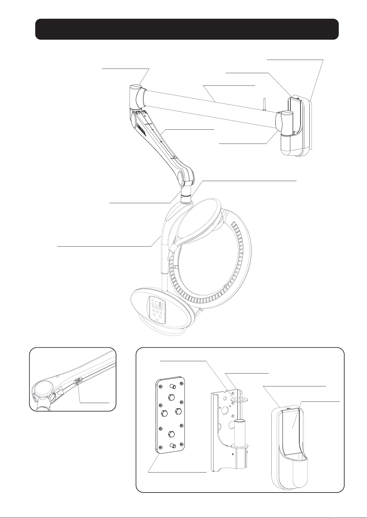
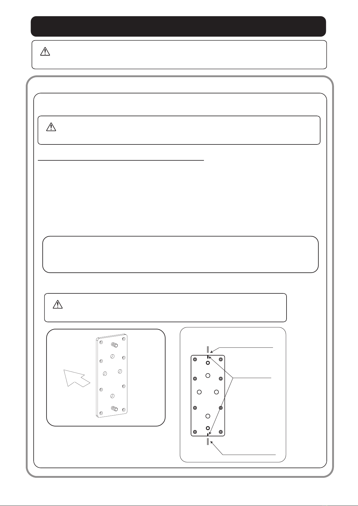
Since a strong force will develop on the wall
bracket, the mounting base of the bracket must
be sturdy enough to support the product and
dryer arm. Do not mount the bracket on a common
rafter, the bar beneath a faced wall, or on
gypsum board alone. Neglecting this caution may
cause the screws to fall off allowing the bracket
to fall due to loose screws from a deformed wall.
IMPORTANT SAFETY INSTRUCTIONS
Persons other than the repair engineer must not
disassemble, repair, or modify the product.
Neglecting this warning may cause ignition or
abnormal operation resulting in physical injuries.
If the pins or the area near the pins of the power
plug are contaminated with waste hair or chemical
agent, wipe the area thoroughly with a dry cloth.
Disconnect the power plug before fixing the product.
Be sure to disconnect the power plug when fixing
the product. Do not connect or disconnect the
power plug with wet hands. Neglecting this
warning may result in an electrical shock or
injuries.
Be sure to execute the daily check.
Execute the daily check according to the “Daily
Inspection Procedure” described in this manual
(page 20). Improper use or operation of the
product may result in injuries or accidents
including burns.
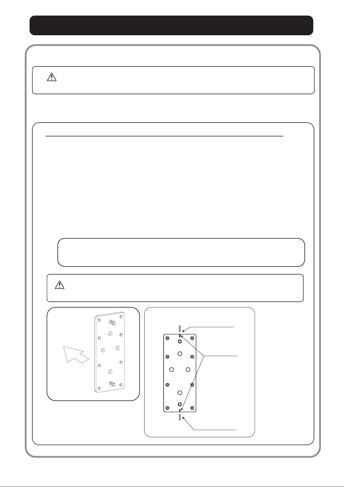
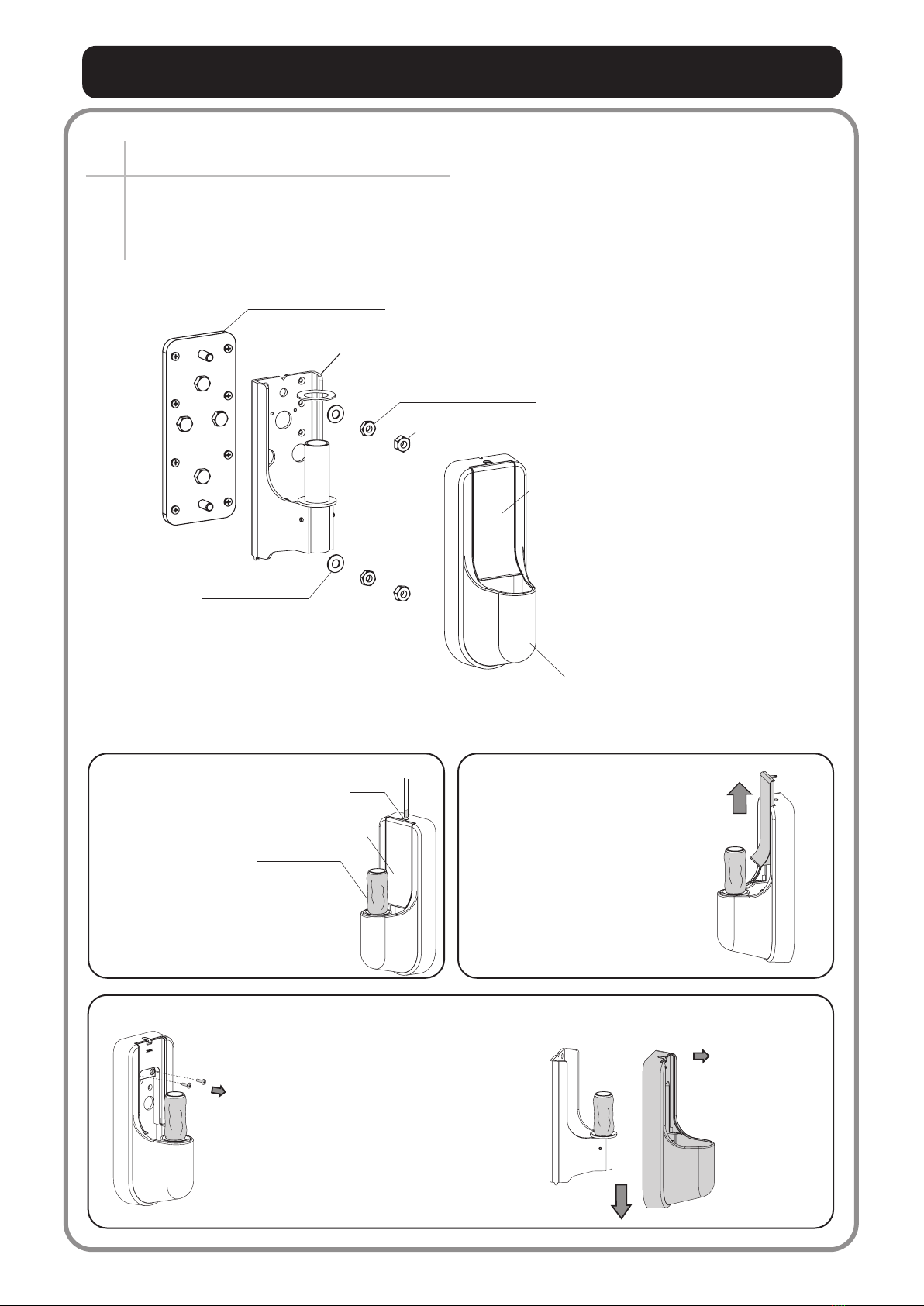
Firmly tighten all nuts and screws.
If the screws are loose, the wall bracket may
come loose allowing the arm to fall.
Do not apply excessive loads.
Resting your arm or leaning on the end of bracket
may cause the balance arm to break or fall
resulting in physical injuries.
Do not install the wall bracket without sufficient
wall support.
An appliance should never be left unattended
when plugged in.
Incorrect detection by the infrared temperature
sensor may cause abnormal heating of the customer
head. In addition, falling of the product may result
in electric shock, fire, or damage.
READ ALL INSTRUCTIONS BEFORE USING. KEEP AWAY FROM WATER.
DANGER
Warning concerning Power Supply. Do not water the equipment.
Always unplug this appliance immediately after
using.
Do not place or store appliance where it can fall
or be pulled into a tub or sink. Do not use while
bathing. Do not place in or drop into water or
other liquid. Do not reach for an appliance that
has fallen into water. Unplug immediately.
To reduce the risk of burns, electroction, fire, or injury to persons:
Be sure to ground the product to use it safely.
If not grounded or inappropriately grounded,
there may be a risk of electric shock when
electric failure or electric leakage occurs.
Contact a qualified installer for grounding.
Customers must not ground the product by
themselves.
Do not ground to:
●Water pipe
Hard plastic is used for many pipes, and it is
not possible to ground to them completely.
●Gas pipe
There are risks of explosion or/and fire.
●Lightning rod and telephone cable

IMPORTANT SAFETY INSTRUCTIONS
3
WARNING
Be sure to use the wall mount plate for mounting the
arm on the wall.
Do not detach the stopper on the dryer arm until all
work is complete.
Never detach the stopper mounted on the balance
arm until installation of the dryer arm is
complete. Detachingthe stopper without installing
the dryer will allow the dryer arm to flip up
resulting in accidents and breakage of the lighting
devices.
Be sure to use the wall mount plate of dryer arm
before mounting the arm on the wall.
Never detach the devices mounted on the dryer arm
by yourself.
Do not install or mount the dryer arm or change the
devices on the dryer arm by yourself.
Only qualified personnel should install and mount
the dryer arm or change the device on the dryer
arm.
Never allow persons other than repair engineers
to detach the devices mounted on the dryer arm.
Failure to heed this warning may result in
breakage or malfunction of surrounding facilities
or physical injuries due to electric shock hazard
or fire.
CAUTION
Handling of power cord. Do not operate the devices in haste.
If the power cord or the power plug is damaged
or when engagement with the wall outlet is loose,
do not use the cord or the plug.
When disconnecting the power plug, do not hold
it at the cord, but pull it off while holding the
plug.
Pay attention to the surrounding areas when operating
the product.
Be sure to verify that no personnel or objects
are within the operating area of the product.
Failure to heed this warning may result in
physical injuries or breakage of surrounding
facilities.
Operate the devices slowly without applying
excessive force. Failure to heed this warning
may result in malfunction, breakage, or falling
of the product.
Never touch the inside of the main unit.
Never touch the inside of the product.
Neglecting this warning may cause an electr-
ical shock. For maintenance and service of
the product, be sure to contact the nearest
dealer or Takara Belmont directly.
Using the wall bracket and the wall plate
which have been deteriorated may cause
bracket to be broken, and device may fall
down.Please contact us about new wall
bracket and wall mount plate.
Do not use the existing (deteriorated) wall
bracket and wall mount plate.
Handling of Power Cord.
Keep the cord away from heated surfaces.
Never operate this product if it has a damaged
cord or plug, if it is not working properly, if it
has been dropped into water. Return the product
to a service center for examination and repair.
Connect this appliance to a properly grounded
outlet only. See Grounding Instructions.

Name of Each Part
4
Wall bracket
Wall bracket cover
Thrust washer
Upper cover
Wall mount plate
Stopper
Balance Arm
End Bracket
Horizontal Arm
Wall Bracket
Rollerball F
(To be purchased separately)
Leading Bracket
End Bracket
Hook falling prevention Cover
Wall mount plate

Accessories
5
Installation Procedures
この取扱説明書及び、商品
につ
いてご不明な点がござ
いましたら、
当社までお問い合わせ
くだ
さい。
(15Pの
ご案内 参照)
このたびは、タカラベルモント製品をお買い上げい
ただき、まことにありがとうございます。
この説明書と保証書をよくお読みのうえ、正
しくお
使いください。そのあと大切に保管
し、必要なときに
お読みください。
Installation / Operation Manual
1 copy 1 piece 1 set
Wall Bracket Screw Set for Wall Bracket
Washer・・・・2 pieces
Nut (type 3)・・・2 pieces
Nut (lock nut)・2 pieces
1 set
Screw Set for wall mount plate
Wood screw・・・ 10 pieces
Coach bolt・・・ 4 pieces
Anchor bolt・ 4 pieces
1 piece
Wall mount plate
2 piece
Adjustment Bar
UP
<Procedures>
1. Installing the wall mount plate ・・・・・・・・・・・・・・
A. Checking the wall base ・・・・・・・・・・・・・
B. Confirming the position of installation ・・・・・・・
C.
Performing installation according to the wall material
・・
2. Installing the wall bracket・・・・・・・・・・・・・・・・
A.Detaching the cover from the wall bracket ・・・・・
B.Securing the wall bracket on the wall mount plate ・・
C.Attaching the cover of the wall bracket ・・・・・・
3. Installing the dryer arm・・・・・・・・・・・・・・・・・P12
4. Installing the processor on the dryer arm・・・・・・・・・・・
A. Detaching the hook ・・・・・・・・・・・・・
B. Attaching the device to the dryer arm ・・・・・・
C. Detaching the stopper of the balance arm ・・・・・
D. Checking the operation・・・・・・・・・・・・・
P6~8
P6
P6
P7~8
P9~11
P9
P10
P11
A.Inserting the rotation-restricting pin
B.Installing the dryer arm
・・・・・
・・・・・・・・・・・
P12
P12
P13~15
P13
P14
P15
P15

■Other materials
In case of using other materials, contact the nearest dealer or Takara Belmont directly.
Pay attention to the correct direction of the wall mount plate.
Install the wall mount plate as shown below.
B. Confirming the position of installation
■Wood
The wall must be reinforced with a high quality wooden column of 120mm~150mm thickness as a base.
The column should be attached vertically.
■Reinforced concrete
Concrete compressive strength should be 200kgf/cm or higher for installing the dryer arm.
A. Checking the wall base
Be sure to ground the product.
Outlet
Ground Terminal
Be sure to use the outlet with
ground terminal, or outlet and terminal.
UP
500 mm max(all four directions)
98 mm
235 mm
Standard height
1900 mm
2
Installation Procedures
In the case that the wall is made of low-strength material such as a gypsum board,
cut the surface of the wall mounting position, and attach a high quality wood such as
plywood. Neglecting this may cause the screws to fall off allowing the bracket to fall
due to loose screws from a deformed wall.
WARNING
1Installing the wall mount plate
Installation procedures differ depending on the
material of the mounting wall surface.
Wall Mount Plate
6
CAUTION

3. Insert and hammer the supplied anchor bolts in the holes. When fixing the wall
mount plate with nuts, check that the perpendicular line on the wall aligns with the
center of both upper and lower holes, and the mark-off lines on the wall mount plate
also align with this line.
In the case that the perpendicular line on the wall misalign from the center of holes,
attach the wall mount plate at the position where the distance from the line to both
the upper and the lower holes to be the same.
Installation Procedures
In the case that wall is made of low-strength material such as gypsum board, cut the surface of the
wall mounting position, and attach high quality wood such as plywood. Neglecting this caution may
allow the wall plate to sink down, or bolts or screws may fall off.
CAUTION
Mark-off lines
UP
Perpendicular line
drawn on the wall
Perpendicular line
drawn on the wall
Wall side
UP
(Front)
(Back)
C. Performing installation according to the wall material
WARNING
After checking the material of the wall, reinforce the wall properly for attaching
the dryer arm. Neglecting this may cause falling accidents.
1. Draw a perpendicular line on the wall.
■Mounting wall made of reinforced concrete
2. Using the wall mount plate as shown in the illustration, drill four holes
(10.5mm Dia. / 60mm - 65mm Deep) on the wall. Check that the perpendicular line
comes to the center of both upper and lower holes.
下図を参照のうえ、取付鉄板を確実に取付けてください。
7
Attach the wall mount plate properly according to the following instructions.

3. Make sure that the mark-off lines on the wall mount plate aline with the perpendicular
line drawn on the wall, then fix the coach bolts tightly. (See below illustration.)
In the case that the perpendicular line on the wall misalign from the center of holes,
attach the wall mount plate at the position where the distance from the line to both the
upper and the lower holes to be the same.
4. Fix the supplied flat wood screws (8 pieces).
Installation Procedures
Fix the supplied coach bolts and wooden screws firmly. Be sure to use all
the supplied bolts and screws. Neglecting of this caution may cause toppling
or falling accidents.
WARNING
Mark-off lines
UP
Parpendicular line
drawn on the wall
Perpendicular line
drawn on the wall
1. Draw a perpendicular line on the wall.
WALL side
UP
(Front)
(Back)
Attach the wall mount plate properly according to the following illustrations.
■Mounting wall made of wood
When attaching the wall mount plate on the wall, be sure to attach it perpendicularly.
Failure to follow this caution may cause tilting of the dryer arm resulting in inproper operation.
CAUTION
After checking the material of the wall, reinforce the wall properly for attaching the dryer
arm. Neglecting this may cause falling accidents.
WARNING
2. Using the wall mount plate as shown in the illustration, drill four holes on the wall. Then,
fix the four pieces of supplied coach bolts temporarily.
C. Performing installation according to the wall material
8

Installation Procedures
9
Installing the wall bracket
2
Install the wall bracket on the wall mount plate
mounted on the wall surface.
* Detach any existing bracket and use the wall bracket
that comes with the dryer arm.
Wall Bracket
A.Detaching the cover from the wall bracket
Wall Mount Plate
Flat Washer
Hex Nut (type 3)
Hex Nut (lock nut)
Upper cover
Wallbracket cover
Upper cover
Bolt
①Detach the upper cover from the
wall bracket cover.
Insert the tip of cross-head screwdriver
into the gap of the upper cover
and detach it.
②Slide the upper cover to upper direction.
③Detach the wall bracket cover.
As per the below illustration, remove the
two bolts on the wall bracket,
using a cross-head screwdriver(No.2).
Slide the wall bracket cover to lower direction,
then take it off forward.
※Please retain the removed bolt,
because it will be used again.
※Please retain the removed bolts,
because it will be used again.
Vynle cover
※Do not detach the vynle cover.

Installation Procedures
10
① Install the wall bracket on the wall mount plate.
B.Securing the wall bracket on the wall mount plate
Wall Mount Plate
Wall Bracket
Wall Bracket
Wall Mount Plate
Flat Washer
Hex Nut (type 3)
Hex Nut (lock nut)
Hex Nut (lock nut)
Flat Washer
Hex Nut (type 3)
Firmly tighten the screws of the wall bracket. If the screws become loose,
the arm may drop resulting in burns or physical injuries to the customers.
WARNING
Thrust Washer

Installation Procedures
11
①Attach the wall bracket cover.
Wall bracket cover
Fix the wall bracket cover as per the below illustration with 2 bolts (detached in P.10 2-③),
using a cross-head screw driver(No.2).
Insert the wall bracket cover from front side, and slide to upper direction.
C. Attaching the wall bracket cover.
②Attaching the upper cover.
Slide the upper cover to lower direction,
and insert it into the wall bracket cover.
Fix the upper cover with a bolt (removed in P.10 2-①),
using a cross-head screw driver (No.2).
Upper cover
Bolt

Installation Procedures
12
A. Inserting the rotation-restricting pin.
B. Installing the dryer arm
Insert the end bracket of the horizontal arm into
the wall bracket shaft. End Bracket
Wall Bracket Shaft
Installing the dryer arm in a narrow space may damage the apparatuses or
equipment if it contacts surrounding equipment.
CAUTION
3
①Put the dryer arm on the card board box used for packing,
and make the horizontal arm and the balance arm a straight state.
②Screw the rotation-restricting pin of below illustration,
and insert it up to the point stopped by E-ring .
Using a flat-head screwdriver.
※Please insert the pin, when the horizontal arm and the balance arm are in a straight state.
Installing the dryer arm
Rotation-restricting pin
E-ring
Horizontal arm
Balance arm Card board box
If the pin isn't inserted, the horiz-
ontal arm and the balance arm
interfere and may cause covers
to be broken.
CAUTION

Installation Procedures
13
Installing the device (processor or dryer) on the dryer arm4
①Remove the fixed bolt of the hook falling prevention cover,
using a cross-head screw driver.
※Please retain the removed bolt, because it will be used again.
②
Hook falling prevention cover
④Detach the hook.
※Please retain the detached hook, because it will be used again.
②Slide the hook falling prevention cover to upper direction.
③Rotate it to the arrow direction.
③
④
Hook
Leading bracket
①
A. Detaching the hook.
When a chemical adheres to the hook cover metal, immediately
wipe it off with a soft, dry cloth. Damage to the cover resulting
from chemicals may cause the main unit to fall.
CAUTION

Installation Procedures
14
Be sure to mount the hook cover metal after installing the hook.
Imperfect insertion of the hook, failure to tighten the screw, or breakage of cover
caused by excessive tightening of the screw may cause the processor to fall.
WARNING
⑤
①
②
<connection finished>
B. Attaching the device to the dryer arm.
①Insert the device suspending the dryer arm to the leading bracket.
※Please insert it up to the point which the hook correspond to the ditch of the rotating shaft.
② Insert the hook which was detached in P.14 4-④to the ditch.
①
②
④
Hook
Rotating shaft
Device
Leading bracket
Hook falling prevention
cover
③Rotate the hook falling cover to arrow direction.
④Slide it to lower direction.
⑤Fix it with the bolt which was detached in P.14 4-①, using a cross-head screwdriver(No.2).
Leading bracket
Rotating shaft
Hook
Hook falling
prevention cover
Correspond to
the ditch.
Insert the hook.
⑥Rotate the device suspending to the dryer arm, then make sure that attaching is finished.
③

Installation Procedures
15
Plug
D. Checking the operation
After inserting the plug into the wall outlet and ground the product, check if the product works without problems.
C. Detaching the stopper of the balance arm
The stopper installed on the balance arm (which is movable in the perpendicular direction) will be required for after-
maintenance. Be sure to mount and secure the stopper in the reverse direction as illustrated.
After detaching the stopper, always check the upperend position of the arm. If it contacts the
lighting devices on the ceiling, adjust it according to the procedures described in the section
"Adjustment of the Balance Arm."
CAUTION
Mount the stopper in the reverse direction.
If the rotating is heavy, please loosen a rotation-restricting pin which is inserted in P.13 1-② approx 1 round,
using the flat-head screwdriver.
Rotation-restricting pin
Stopper

Adjustment of the Balance Arm
16
1.Adjusting the lift angle of the balance arm.
If the ceiling is low or the balance arm interferes with lighting equipment, adjust the lift angle
of the balance arm.
Rotate and adjust the adjustment screw in the counterclockwise direction to stop the arm at the
specified height. The adjustment differs depending on the angle.
The adjustment bar is packed together with this product and the operation manual
(A)In the case that lowering the upper-limit angle of the balance arm.
①Use the adjustment bar which is packed together with the
operation manual.
②Move the balance arm up and down and then set it in the
position where the adjustment screw hole can be seen in
the upper-limit angle adjustment hole.
③Insert the adjustment bar into the adjustment screw hole,
and rotate it into the “go down” direction.(See the
illustration above.)
※Since the amount of the adjustment is not constant,
check the balance each time the screw is rotated.
(B)In the case that rising the upper-limit angle of the balance arm.
①②Follow the same procedures as Item (A) above.
③Insert the adjustment bar into the adjustment screw hole,
and rotate it into the “go up” direction.(See the
illustration above.)
※Since the amount of the adjustment is not constant,
check the balance each time the screw is rotated.
Adjustment bar
Upper-limit angle
goes down.
Upper limit angle
adjustment hole
Adjustment screw hole
Upper limit angle
adjustment hole
Adjustment bar
Upper-limit angle
goes up.
Make sure that the balance arm does not contact any other equipment, such as lighting devices on
the ceiling, when the arm is in the upper-limit position. Installation of the arm without checking
the state may allow the arm to contact lighting equipment resulting in damage.
CAUTION

Balance arm
Balance adjustment hole
+side
-side
Adjustment screw hole
balance adjustment hole
Adjustment bar
Adjustment Bar
Adjustment of the Balance Arm
17
2.Adjusting the balance of the balance arm.
If the dryer or the processor mounted on the balance arm is not balanced in the specified position,
then adjust the balance.
(A) In the case that the suspended device goes up from the lower-limit position.
①Move the balance arm up and down and then set it in the position where the adjustment screw
can be seen in either of the two punch holes (See the illustration at the right).
②Insert the adjustment bar into the adjustment screw hole and rotate it in the (-) direction.
Since the amount of the adjustment is not constant, check the balance each time the screw is rotated.
(B)The suspended device goes down from the upper-limit position.
①Move the balance arm up and down and then set it in the position where the adjustment screw
can be seen in either of the two punch holes (See the illustration at the right).
②Insert the adjustment bar into the adjustment screw hole and then rotate it in the (+) direction.
Since the amount of the adjustment is not constant, check the balance each time the screw is rotated.
If the balance adjustment is imperfect, the suspended device cannot be held in the specified
position, which causes the main unit to descend during practice, resulting in burns or physical
injuries to personnel.
CAUTION

Operating Procedures
18
1. Hold the device (processor or dryer)
mounted at the leading end of the dryer
arm and move it to the customer's
position.
When setting the product, pay attention so that the dryer arm or the device will not
contact surrounding facilities or personnel. Furthermore, move the product by holding
the product by the grip; move slowly and safely. Failure to heed this warning may
cause burns or physical injuries due to product damage.
CAUTION
2.After using the device, fold the dryer arm.
wax
Abrasive
Compound
Care and Maintenance
Be sure to disconnect the power plug from the wall
outlet for maintenance and cleaning of the product.
The plastic, plated, or painted parts should be
wiped with a dry and soft cloth.
Never use volatile chemicals such as thinner, alcohol, gasoline, and kerosene; detergents containing organic materials;
acidic-, alkaline- or chlorine-based detergents; and wax containing abrasive compound, sponge, scrubber, etc.
Splashing of water on the control panel or metal parts
may result in product failure or rusting.
Immediately dry the product with a soft cloth.
When fixed contamination or oil adheres to the product,
wipe it off with a damp cloth with a water-diluted neutral
detergent.
Kerosene
Alcohol
Thinner
Chemicals
Soft cloth
The product should not be exposed to moisture and water.
Soft cloth
Soft cloth
Power plug
Neutral
Detergent

19
WARNING
Checks before operating the product:
Daily Inspection Procedure
Be sure to execute daily inspection according to the following guidelines. Continued use without executing the
daily inspection may result in failure or accidents.
To use the product safely, be sure to execute the following inspections.
■Daily Inspection Items (Pre-Operation Check)
Inspection Item Inspection Procedures If the inspection result is unacceptable
□Check if there is no
deformation, breakage, or
deterioration on the power
plug or the power cord. □ There is no deformation, breakage,
or deterioration of the power plug
or the power cord.
Checks while the product is in
operation (this is limited to the case
that there is no deformation,
breakage, or deterioration of the
power plug or the power cord.)
□ The power plug or the power cord
may be heated when it is
deteriorated. While the product is in
use, touch the power plug and the
power cord with a hand and make
sure that they are not hot.
□Make sure the wall bracket is
not loose.
Move the device mounted on the dryer
arm and check the action.
□Make sure the device mounted
on the dryer arm is not loose.
Move the device mounted on the dryer
arm and check the action.
□Make sure the dryer arm
operates safely without any
problem.
Move the device mounted on the dryer
arm and check the action.
If you suspect something is wrong,
disconnect the power plug and
immediately contact the nearest
dealer or Takara Belmont directly.
There is a possibility of electrical
shock or burn injuries due to fire or
electrical leakage. Since some parts
must be replaced, immediately stop
using the product, turn off the power
plug, and immediately contact the
nearest dealer or Takara Belmont
directly.
If you suspect something is wrong,
such as the bracket swings at the
base part on the wall, disconnect the
power plug and immediately contact
the nearest dealer or Takara Belmont
directly.
If you suspect something is wrong,
such as the arm swings at the
connecting part, disconnect the
power plug and immediately contact
the nearest dealer or Takara Belmont
directly.
Any other servicing should be performed by an authorized service representative.
Table of contents