Takara Bio Apollo User manual

Takara Bio USA, Inc.
1290 Terra Bella Avenue, Mountain View, CA 94043, USA
U.S. Technical Support: technical_support@takarabio.com
United States/Canada
800.662.2566
Asia Pacific
+1.650.919.7300
Europe
+33.(0)1.3904.6880
Japan
+81.(0)77.565.6999
Page 1 of 33
Takara Bio USA, Inc.
Apollo™ System User
Manual
Cat. No. 640078
(080719)

Apollo™ System User Manual
(080719) takarabio.com
Takara Bio USA, Inc.
Page 2 of 33
Table of Contents
I. Introduction..................................................................................................................................................................... 4
II. List of Components......................................................................................................................................................... 4
III. Safety Information ...................................................................................................................................................... 5
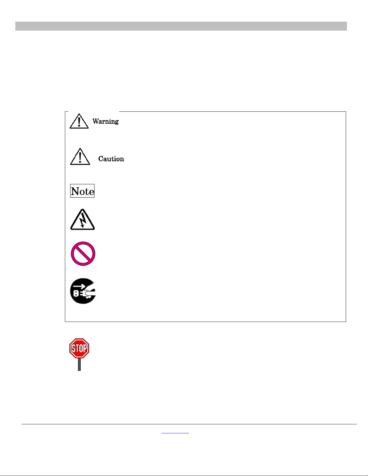
A. Symbols....................................................................................................................................................................... 5
B. Installation and Storage............................................................................................................................................... 6
C. Precautions for Instrument Operation ......................................................................................................................... 6
D. Warranty Period .......................................................................................................................................................... 6
E. Abolishment................................................................................................................................................................ 6
F. Actions in Case of Emergency.................................................................................................................................... 7
IV. Specifications.............................................................................................................................................................. 7
A. Features....................................................................................................................................................................... 7
B. Performance Specifications......................................................................................................................................... 8
C. Size, Weight and Power Requirements....................................................................................................................... 8
D. Environmental Requirements...................................................................................................................................... 8
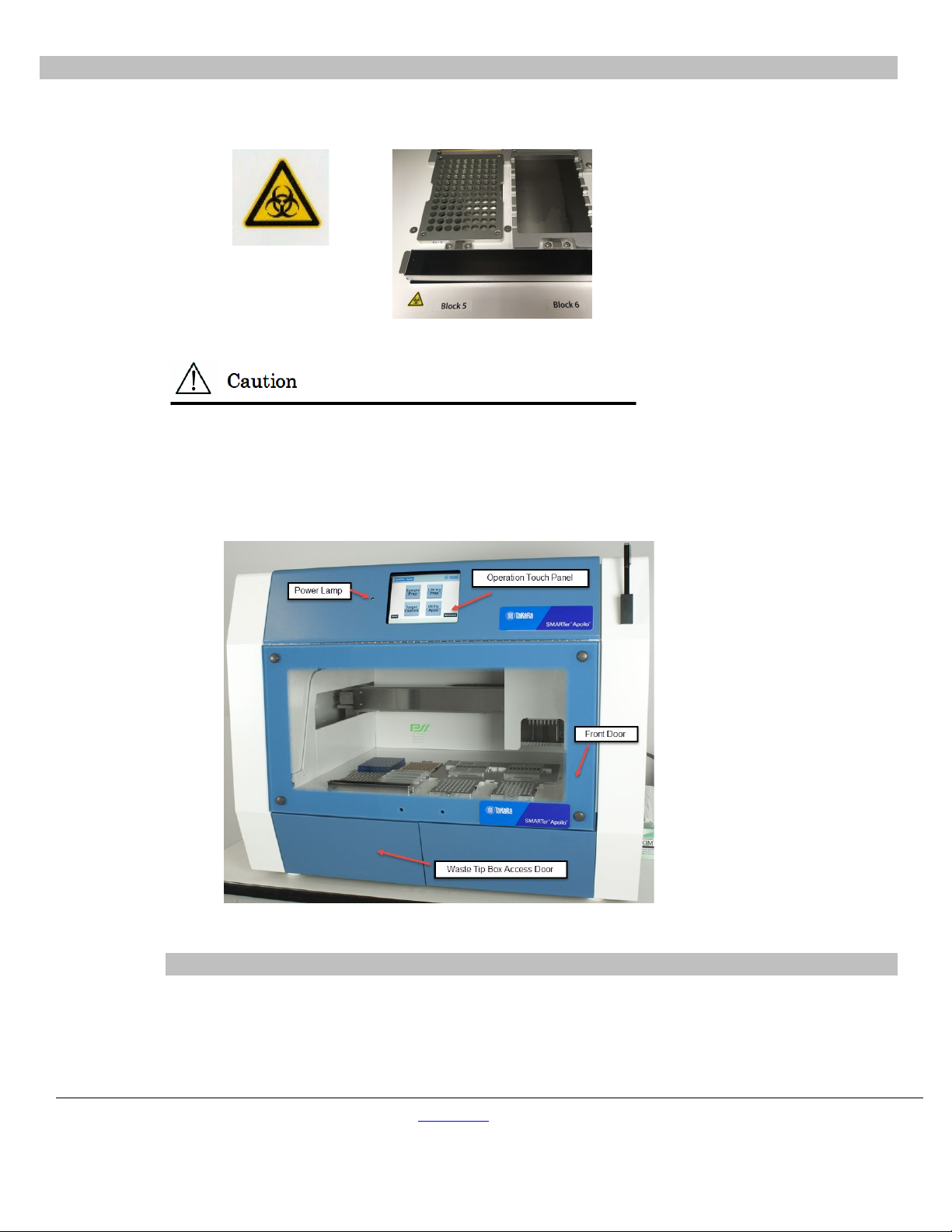
E. About Caution Labels Inside the Instrument .............................................................................................................. 9
V. System Components...................................................................................................................................................... 10
A. Front View ................................................................................................................................................................ 10
B. Right-side View ........................................................................................................................................................ 11
C. Internal Components................................................................................................................................................. 12
VI. Installation................................................................................................................................................................. 13
A. Setup Procedure ........................................................................................................................................................ 13
VII. Accessories and Disposables .................................................................................................................................... 16
A. Accessories ............................................................................................................................................................... 16
B. Disposables ............................................................................................................................................................... 18
C. Reagents.................................................................................................................................................................... 19
VIII. Directions for Use ..................................................................................................................................................... 19
A. Front Door Operation................................................................................................................................................ 19
B. Putting on and Taking out the Waste Tip Box.......................................................................................................... 20
C. Setting Racks and Disposables in Place.................................................................................................................... 21
IX. Basic Operation......................................................................................................................................................... 23
A. Start Up and Shut Down Procedure .......................................................................................................................... 23
B. Touch Panel Operation.............................................................................................................................................. 23

Apollo™ System User Manual
(080719) takarabio.com
Takara Bio USA, Inc.
Page 3 of 33
C. Running a GUI Protocol ........................................................................................................................................... 24
D. Running a User Maintenance Protocol ..................................................................................................................... 25
E. About Page................................................................................................................................................................ 26
X. Instrument Care and Maintenance ................................................................................................................................ 26
A. Cleaning Procedure................................................................................................................................................... 27
B. Greasing O-rings ....................................................................................................................................................... 27
XI. Troubleshooting ........................................................................................................................................................ 29
A. Error Reported During Protocol Run ........................................................................................................................ 29
B. Suspending or Aborting a Protocol Run ................................................................................................................... 29
C. Frequently Reported Problems.................................................................................................................................. 30
XII. List of Common Error Codes.................................................................................................................................... 31
Appendix............................................................................................................................................................................... 32
A. Recovering a Run After a Crash ............................................................................................................................... 32
B. Resetting the Apollo system axes after a crash......................................................................................................... 32
Table of Figures
Figure 1. Requirements for proper placement of the Apollo system ...................................................................................... 9
Figure 2. Front view of the Apollo system. .......................................................................................................................... 10
Figure 3. Right-side view of the instrument showing the position of Power Inlet Connector and the Fuse Unit................. 11
Figure 4. Location of the Magtration Unit and the Stage Unit inside the instrument........................................................... 12
Figure 5. Image showing the location of the disposables on the Stage Unit......................................................................... 13
Figure 6. Image showing the operation of the Front Door.................................................................................................... 20
Table of Tables
Table I. List of components provided with the Apollo system. .............................................................................................. 4
Table II. List of accessories provided with the instrument. .................................................................................................. 16
Table III. Disposables available from Takara Bio ................................................................................................................ 18
Table IV. Maintenance checklist .......................................................................................................................................... 26
Table V. Frequently reported problems ................................................................................................................................ 30
Table VI. List of error codes................................................................................................................................................. 31

Apollo™ System User Manual
(080719) takarabio.com
Takara Bio USA, Inc.
Page 4 of 33
I. Introduction
We appreciate your purchase of the Apollo system, which utilizes Magtration® technology for separation of
magnetic particles. This manual is a guide for the user to operate the instrument safely and effectively. Please read
this manual thoroughly to understand the instrument before starting operation. Keep this manual close to the
instrument as a quick reference for all the operators as needed.
•Do not operate the instrument without fully understanding instructions described in this manual.
•Always keep this manual handy for easy reference at any time.
•Please inform us if this manual is lost or damaged.
II. List of Components
Table I. List of components provided with the Apollo system.
No.
Description
Qty.
Remarks
1
Apollo System Main Body
1
2
Front Door Handle
1
With 2 fixing screws
3
96 Tip Rack
3
4
Reagent Reservoir Rack
1
5
Mini-Tube Rack
1
For 1.1 ml tubes
6
PCR Tube Retention Plates
2
7
Waste Tip Box
1
Content
8
Waste Chute
1
9
Stylus Pen
1
10
Stylus Pen Holder
1
11
AC240V Power Cable
1
12
AC110V Power Cable
1
13
O-rings
8
14
Silicon Grease
1
For O-rings
15
Fuse
1
16
User Manual
1
This manual
17
Package Checklist
1

Apollo™ System User Manual
(080719) takarabio.com
Takara Bio USA, Inc.
Page 5 of 33
III. Safety Information
Most problems occur from improper use of the instrument and when safety instructions are not followed. Please
read this manual thoroughly to understand and to get familiar with preventive measures so any problems in
instrument operation can be avoided.
A. Symbols
In this manual we put symbols next to important instructions regarding safe use of the instrument. Details
of all symbols are provided below.
This symbol indicates the possibility that one could be killed or seriously injured when
an incorrect operation is performed.
This symbol indicates the possibility that one could be injured when an incorrect
operation is performed.
Denotes information to be emphasized or added for important points. You are advised
to pay close attention to these when operating the instrument.
This symbol indicates caution against electric shock.
This circled symbol indicates actions that are prohibited. Details are illustrated inside
or next to the symbol.
The closed circle symbol is used to restrict operations or to illustrate what to do.
Details are illustrated inside the symbol (the sample on the left shows unplugging of
the AC plug from a wall outlet).
The following precautionary instructions are included to ensure the safe operation of
your Apollo System. Please always keep this manual near the instrument or operator.
Failure to comply with the instructions in this manual will void the manufacturer’s
warranty. If the instrument is not performing as expected, immediately turn off the
main-power switch and unplug power cable, then contact us.

Apollo™ System User Manual
(080719) takarabio.com
Takara Bio USA, Inc.
Page 6 of 33
B. Installation and Storage
Avoid the following places for the installation of this instrument. Installing this instruments in such places
may cause damage to the instrument.
Do not install in a place with
•direct sunlight
•vibration, high humidity or dust
•strong electric or magnetic
fields
•possibility of liquid or oil
splashing on the instrument
•flammable or corrosive gas or
high heat
Unplug power cable from wall outlet when
instrument is likely to not be in use for extended
periods of time.
C. Precautions for Instrument Operation
•To eliminate the possibility of biohazard contamination from samples or extracted/purified products,
use a mask, goggles and gloves while operating the instrument for your safety.
•Pay close attention when handling samples with high risk of biohazard.
•When operating the instrument under low temperature conditions, keep the instrument powered on
even when not in use.
•Be sure to avoid any foreign materials from getting into the instrument.
•Do not scratch or press the operation panel using knives or things with sharp edges.
•Replacement of the fuse shall be made by field service personnel authorized by Takara Bio. Please
contact us for fuse replacement.
D. Warranty Period
•12 months after installation, regardless of use.
•This warranty excludes the problems derived from inadequate storage, improper use or operation,
repair/modification/maintenance of the instrument by people who are not authorized by us, even
within the warranty period.
E. Abolishment
Contact us when you want to recycle the instrument.

Apollo™ System User Manual
(080719) takarabio.com
Takara Bio USA, Inc.
Page 7 of 33
F. Actions in Case of Emergency
In the instance when the instrument gets extremely hot, is
smoking, giving off an abnormal smell, etc., immediately unplug
the power cable from the wall outlet to avoid fire or electric shock
to you and contact us for repair.
When foreign material or water splashes over or gets inside the
instrument, immediately unplug the power cable from the wall
outlet to avoid fire or electric shock to you and contact us.
When the power cable is damaged (core wire exposed or broken),
immediately unplug the power cable from the wall outlet to avoid
fire or electric shock to you and contact us.
IV. Specifications
The Apollo system provides a complete, walkaway solution for next-generation sequencing (NGS) library-prep
applications using validated protocols and chemistries. In addition to library prep, the Apollo system also employs
in-tip magnetic bead separation, for a variety of magnetic bead applications such as PCR clean up, poly A
enrichment, rRNA depletion, and size selection.
A. Features
•Simple operation using a graphical user interface
•Compact design with minimal installation footprint
•High availability of various types of magnetic particle reactions by using special protocol
development software
•Simultaneous processing of up to 8 samples by 8 nozzles (batch processing of up to 96 samples)
•Reduced running cost by using reagent dispensing function and by using commercially available
microtiter plates

Apollo™ System User Manual
(080719) takarabio.com
Takara Bio USA, Inc.
Page 8 of 33
B. Performance Specifications
Instrument type:
Desktop
Throughput:
Samples: 1–96 samples/batch depending on protocol type
Processing time: about 30 min/ 1–8 samples
Temperature control:
Two Heat/Cool Blocks: 4–95°C
Handling volume:
5–200 µl
Dispensing accuracy*:
5–10 µl less than CV 20 %
11–20 µl less than CV 10%
21–200 µl less than CV 2%
* Accuracy was measured with distilled water at room temperature 20–25°C.
NOTE: Processing time depends on the protocol being performed.
C. Size, Weight and Power Requirements
Size: 800 mm (W) x 700 mm (D) x 675 mm (H) (disregarding prongs)
Weight: 97 kg (~214 lbs) (excluding accessories and disposables)
Power Required: AC100 – 240 V, 50/60 Hz, 440 VA
•Do not share power source with other instruments.
•Do not place close to noisy instruments or instruments with power fluctuation.
•Connect power cable to wall outlet with ground line.
D. Environmental Requirements
Temperature: 15°C–30°C
Relative Humidity: 15–75% Non-condensing
Altitude: Up to 2,000 m
Space: maintain a minimum distance between the walls and instrument as shown below for ventilation,
maintenance work, etc. Also keep more than 200 mm of space above the instrument.

Apollo™ System User Manual
(080719) takarabio.com
Takara Bio USA, Inc.
Page 9 of 33
Figure 1. Requirements for proper placement of the Apollo system. The instrument should be placed such that there is a
distance of at least 200 mm between the instrument and any surrounding walls.
•Place the instrument on a horizontal surface.
•Do not place the instrument where there is direct sunlight or vibration.
•When operating the instrument in a cold chamber or cold room, keep the instrument powered
on even when not in use to avoid formation of dew.
E. About Caution Labels Inside the Instrument
1. Caution label for high temperature
Place attached: Heat/Cool Block
The part where the yellow label is attached becomes hot (see image above). Do not touch this area
while handling the instrument.
Apollo system

Apollo™ System User Manual
(080719) takarabio.com
Takara Bio USA, Inc.
Page 10 of 33
2. Caution Label for Biohazard
Place attached: Waste Chute
The part where this label is attached (inside cover) has the possibility of biohazard contamination
with samples or extracted/purified products. Take care to avoid contamination.
V. System Components
A. Front View
Figure 2. Front view of the Apollo system.
NOTE: The Power Lamp lights up (green light) when the machine is powered on.

Apollo™ System User Manual
(080719) takarabio.com
Takara Bio USA, Inc.
Page 11 of 33
B. Right-side View
On the right side of the instrument, the Power Switch is located towards the front and the Power Inlet
Connector and Fuse Unit are located towards the back.
Figure 3. Right-side view of the instrument showing the position of Power Inlet Connector and the Fuse Unit.
1. Details of the Right-side View (Front)
2. Details of Right-side View (Back)
NOTE: Replacement of the fuse should be performed by field service personnel authorized by
Takara Bio. Contact us regarding fuse replacement.

Apollo™ System User Manual
(080719) takarabio.com
Takara Bio USA, Inc.
Page 12 of 33
C. Internal Components
The Magtration Unit and the Stage Unit are located inside the instrument.
Figure 4. Location of the Magtration Unit and the Stage Unit inside the instrument.
Magtration Unit
Nozzle Unit: This unit has 8 nozzles to process up to 8 samples simultaneously with accurate and rapid
aspiration/dispensing.
Magnet: Eight powerful magnets are aligned with 8 tips to simultaneously separate magnetic particles for
up to 8 samples.
Stage Unit
Heat/Cool Unit:(indicated by the red box in Figure 4, above)
Two Heat/Cool Units are equipped and can hold PCR plates. Temperature can be set from 4 to 90°C
depending on protocols.
Rack Holder:(indicated by the green box in Figure 4, above)
Racks and Disposables to be used vary by protocols. Refer to the application manual of the protocol you
are following for details.
Waste Chute: It leads the waste tips and liquid to the Waste Tip Box.
Example of loading racks and disposables

Apollo™ System User Manual
(080719) takarabio.com
Takara Bio USA, Inc.
Page 13 of 33
Figure 5. Image showing the location of the disposables on the Stage Unit.
96 Tip Rack: Holds 8 x 12 DN70 Tips.
Reagent Reservoir Rack: Holds Reagent Container L.
Microtiter Plates: Holds 96-well Microtiter plates.
Waste Chute: Place where waste tips, etc. are discarded.
NOTE: The above layout is an example and will vary by protocol.
VI. Installation
A. Setup Procedure
NOTE: Setup should be performed by Field support personnel authorized by Takara Bio.
1. Remove protection films attached on the instrument.
2. Open Front Door and fix Grip of Front Door by two screws (supplied).

Apollo™ System User Manual
(080719) takarabio.com
Takara Bio USA, Inc.
Page 14 of 33
3. Remove the fixing jig for X-Axis Magtration Unit fixed by 3 screws inside the instrument.
4. Remove cushioning and desiccant agents.
5. Open Right-side Cover by removing 2 fixing screws.
6. Remove Y-Axis fixing jig to right-side base by removing 3 fixing screws. Then replace Right-side
Cover and fix it with two screws.

Apollo™ System User Manual
(080719) takarabio.com
Takara Bio USA, Inc.
Page 15 of 33
7. Open Left-side Cover by removing 2 fixing screws.
8. Remove Y-Axis fixing jig to left-side base by removing 4 fixing screws. Then replace Left-side Cover
and fix it with two screws.
9. Connect Power Cable to Power Inlet Connector on the right side of the instrument. Then turn Power
Switch on assuring that Front Door and Waste Tip Box Door are closed securely.

Apollo™ System User Manual
(080719) takarabio.com
Takara Bio USA, Inc.
Page 16 of 33
Do not use power cable other than the one provided to avoid temporary blackout or fire breaking.
10. Installation Completed
When transferring the instrument, make sure that all the fixing jigs for all axes are attached
securely and that cushioning is set between the Magtration Unit and the Stage Unit to protect
nozzles from free movement.
VII. Accessories and Disposables
A. Accessories
Table II. List of accessories provided with the instrument.
Description
Qty.
96 Tip Rack
3
Reagent Reservoir Rack
1
Mini-Tube Rack
1
PCR Tube Retention Plates
2
Waste Tip Box
1
Waste Chute
1
Stylus Pen
1
Stylus Pen Holder
1
AC240V Power Cable
1
AC110V Power Cable
1
O-ring
8
Silicon Grease
1
Fuse
1
•96-Tip Rack
Holds DN70 Tips, up to 8 x 12 pieces.

Apollo™ System User Manual
(080719) takarabio.com
Takara Bio USA, Inc.
Page 17 of 33
•Reagent Reservoir Rack
Holds up to 4 Reagent Containers.
•Waste Tip Box
The Waste Tip Box receives discarded tips coming down through the Waste Chute.
•Waste Chute
The Waste Chute directs discarded tips to the Waste Tip Box.
•Stylus Pen
The Stylus Pen is used to operate the instrument through the Touch Panel. It operates like a ballpoint pen.

Apollo™ System User Manual
(080719) takarabio.com
Takara Bio USA, Inc.
Page 18 of 33
•Stylus Pen Holder
The Stylus Pen Holder is a holder for the Stylus Pen and can be magnetically attached onto the
instrument surface.
B. Disposables
1. Disposables available from Takara Bio
Table III. Disposables available from Takara Bio
Cat. No.
Product Description
640089
Apollo 96 Tip Rack
640085
Apollo Piercing Tips
640084
Apollo Filter Tips
640082
Apollo 0.2 ml PCR 8-Tube Strips, Clear
640086
Apollo Caps for 0.2 ml PCR 8-Tube Strips, Clear
640083
Apollo Microtiter Plates
640087
Apollo Reservoirs
640088
Apollo 1.1 mL MiniTubes

Apollo™ System User Manual
(080719) takarabio.com
Takara Bio USA, Inc.
Page 19 of 33
•Apollo Reservoirs (Cat. No. 640087)
•Apollo Filter Tips (Cat. No. 640084)
C. Reagents
Refer to your specific application manual for reagents to be used and directions for use.
•Do not reuse any disposables/reagents to avoid contamination or instrument malfunction.
•Do not use disposables/reagents other than specified to avoid instrument malfunction.
•When discarding disposables, follows the instructions defined by your facility or regional laws.
VIII. Directions for Use
A. Front Door Operation
The Front Door moves up and down, and it is held at the top when fully moved up. Hold only the
Grip/handle of the Front Door to open or close the door to avoid getting your fingers pinched. The Front
Door is locked during operation. Open the Front Door after the instrument has finished its operation.

Apollo™ System User Manual
(080719) takarabio.com
Takara Bio USA, Inc.
Page 20 of 33
Figure 6. Image showing the operation of the Front Door.
•If the Front Door is not opened to its uppermost position, it may come down and your hand or
fingers might be pinched. Make sure to move the Front Door to its uppermost position when
working.
•Move Front Door gently without giving excessive force to avoid damaging it.
B. Putting on and Taking out the Waste Tip Box
1. Waste Chute
The Waste Chute can be removed by taking it out from Waste Tip Discard Hole for cleaning.
2. Waste Tip Box
The Waste Tip Box can be removed for discarding tips or for cleaning. Open the Front Door first and
then open the access door for the Waste Tip box. Take out the Waste Tip Box by holding its grip.
Make sure that the access door for the Waste Tip Box is closed after setting the Waste Tip Box,
otherwise you cannot start a protocol run.
Table of contents
Popular Indoor Furnishing manuals by other brands

Freedom
Freedom SE-0609 Assembly instructions

Inspire
Inspire 203-101GY/GY Assembly instructions

Askona
Askona Trenton sofa Assembly instructions

Hailey Home
Hailey Home CT0144 Assembly instructions

Furniture of America
Furniture of America Egaleo CM5814TV Assembly instructions

Ilva
Ilva 1051552 Assembly instruction