Rollshutter Installation Instructions, 7
©Copyright TALIUS
3.1a) Tape Operator (all types): If the control tape will travel through a wall look for an exit hole of approximately Ø1"
(Ø25mm) in diameter in one of the lower back corners of the panel box. Hold the panel box and rails against the
opening and mark the location of the hole on the opening. On the marked location drill a pilot hole of approximately
Ø3/8" (Ø10mm) in diameter horizontally through the wall. Have a helper safely hold a piece of wood over the location
the hole will exit the interior wall. Once the pilot hole is satisfactory, increase the diameter to Ø3/4" (Ø20mm). The
hole can angle up or down somewhat, but it should allow very little side-to-side movement.
3.1b) Crank Rod Operator with Gear or Manual Override Motor: If the job consists of several units it is important to be
aware that there are various gears and/or manual override motors that require different sized connectors. For example
there are 6x6mm and 8x8mm square connectors, and 7mm hexagonal connectors that look rather similar. If the job
contains different sized connectors, push each one into a gear or manual override motor until each connector is
matched up satisfactorily to a Rollshutter unit before proceeding with this section. On the marked location drill a pilot
hole of approximately Ø3/8" (Ø10mm) in diameter through the wall. Have a helper safely hold a piece of wood over the
location the hole will exit the interior wall. The drilling must be performed at the pitch that was previously determined.
Once the pilot hole is satisfactory, increase the diameter to ؽ" (Ø13mm). The hole must be straight and allow no
side-to-side movement.
If the connector rod of the universal will travel through a wall look for an exit hole of approximately Ø1" (Ø25mm)
diameter in one of the corners in the lower or middle back of the panel box. Hold the panel box and rails against the
opening and mark the location of the hole on the opening. Then insert the connector rod and universal through the
back of the panel box into the gear or manual override motor and note the pitch of the rod. The pitch will often be
somewhere between horizontal to 45º downward.
3.1c) Torsion Spring Operation: Proceed to Section 4.
3.1d) Motor Operator: An exit hole for the power cable of approximately Ø3/4" (Ø19mm) will need to be drilled in one
of the back corners of the panel box. The hole is not drilled at the factory because of site variation. Remove the lid and
look for the motor side. Proceed to drill a hole of desired size and location within the panel box endplate. Hold the
panel box and rails against the opening and mark the location of the hole on the opening. An electrician should cover
any cable exiting the panel box with a sleeve to prevent cutting of the wires by the endplate. On the marked location
the electrician will drill a hole of approximately Ø3/8" (Ø10mm) diameter horizontally through the outer layer of the
wall. The electrician will later run the wires through the inside of the wall into the hole at the back of the panel box. If
the Rollshutter contains a manual override then also follow section 3.1b on crank rod operators.
Section 4: Pre-Drilling Guide Rails
NOTE: If you have ordered your rails with pre-drilling by-pass this section
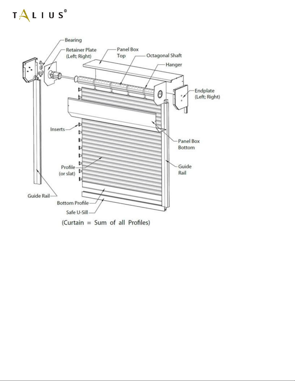
The guide rails are the main supports that hold up a Rollshutter unit and will later need to be fastened securely. When
drilling through two layers of aluminum the hole through the outer layer must be Ø8.5mm (Ø11/32") precisely for the
screw caps, or Ø10mm (Ø3/8") for screw caps for security or high-wind applications. The hole through the inner layer
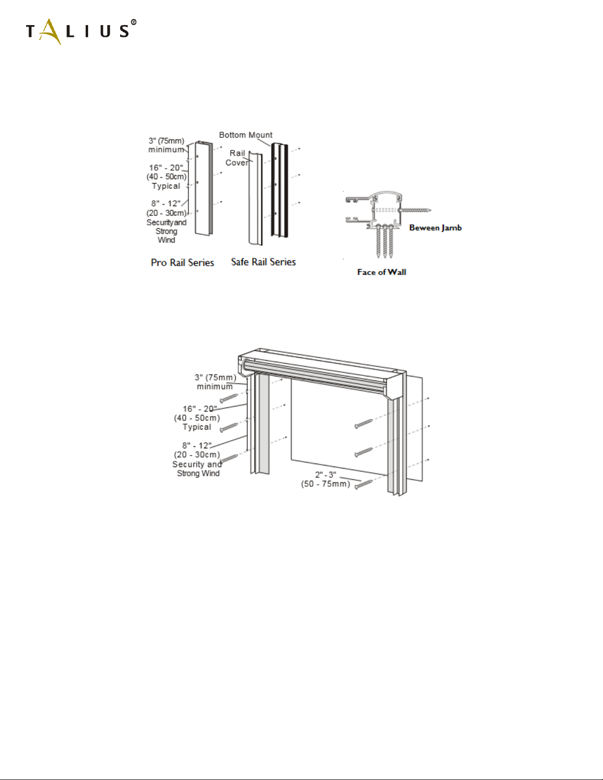
should be approximately Ø5mm (Ø3/16"). For two-piece safe rails, drill only a Ø5mm (Ø3/16") hole through one layer –
the bottom mount piece. If there are many holes to drill the factory can supply at reasonable cost a step drill bit that
drills both holes simultaneously. Normally the holes should be spaced no more than 16" - 20" (40 - 50cm) apart, but for
security and high-wind applications the spacing should be 8" - 12" (20 - 30cm). Ensure that the first and last holes are no