2
•
MINOR CUTTING HEIGHT
ADJUSTMENTS
1. This unit can be adjusted to offer a cutting height
range simply by adjusting the roller assembly.
2. As you follow the instructions below, refer to fig. 3 for
more information.
3. To achieve the lowest cutting position, loosen and
remove the nuts on both sides of the roller assembly.
Position the bolt through the bottom hole of the plas-
tic roller bracket and top hole of the mower side plate.
4. To achieve the highest cutting position, loosen and
remove the nuts on both sides of the roller assembly.
Position the bolt through the top hole of the plastic
roller bracket and bottom hole of the mower side
plate.
5. Other cutting heights can be obtained by positioning
the bolts through other hole locations.
•
MOWER BLADE ADJUSTMENT
1. The blades have been preadjusted before leaving the
factory.
2. Misalignment can occur resulting in blades that are
too loose or too tight. If this happens, you will notice
a rough, uneven cut or hard-pushing mower.
3. All adjustments are made from the rear of the mower
(opposite from the bar with the logo decal). Each end
of the cutting bar can be adjusted separately.
4. As you follow the instructions below, refer to Fig.4 for
more information.
5. The cutting bar blade (located under the reel) pivots.
The front screws move the cutter bar away from the
blades, while the rear screws move the cutter bar
toward the blades.
6. Adjusting the screws is a very sensitive procedure. 1-
16th of a turn is considered a major adjustment.
7. Before tightening one adjusting screw, be sure to
loosen the opposing screw an equal amount.
•
LOOSENING THE BLADES:
1. The cutter bar blade being moved further from the
cutting reel.
2. Loosen both knob equally by turning them counter-
clockwise.
•
TIGHTENING THE BLADES:
1. The cutter bar being moved closer to the cutting reel.
2. Tighten both knob equally by turning them clockwise.
•
CHECKING ADJUSTMENTS:
1. Turn mower upside down.
2. Insert a piece of paper (i.e., writing or newspaper
between the cutter bar and the reel blades, and care-
fully turn the reel blades by hand.
3. All blades should slice the paper evenly for the entire
length of the cutter bar while the reel turns smoothly.
4. If the mower has an intermittent cut, adjustment should
be made to the appropriate side of the blades to attain
proper cutting action.
•
SHARPENING THE CUTTING BLADES :
1. When the mower is properly lubricated and adjusted,
sharpening should not be necessary for several years.
However, the following steps will allow you to do the
procedure yourself at relatively little expense.
2. Spread a thin layer of lapping compound on the front
edge of the reel blades.
3. Adjust the cutter bar so that the cutter bar blade has
light but firm contact with the reel blades across the full
width of the cutter bar.
4. Turning the reel blades backward, until the reel blades
rotate retativety free and the front edge of the cutter bar
blade is polished.
5. Remove wheels; reverse pinions and pawls so that the
beveled edge of the pawl is on the right.
Adjusting
Screws
Fig. 4
Front
Rear
AU
3
• Inspect your lawn for any debris or foreign objects and
remove them before mowing.
• Never place your hands, fingers or feet inside the reel.
Although not powered by a motor, when the wheels
turn, the reel cuts.
• Never mow when the grass is wet and slippery.
• Don’t place your hands or feet near a moving part of
the mower.
• Don’t operate the mower while barefoot or wearing
sandals.
• Walk slowly, never run. Always be sure of your footing
when operating the mower.
• Never intentionally ram trees, fences, etc. This can
cause injuries or severely damage the mower.
• Remember that this mower is a precision piece of lawn
care equipment. Treat it as such by exercising caution
when using it.
• Make sure your mower is in safe operating condition.
Don’t attempt to operate the mower if it is damaged.
Have it repaired first.
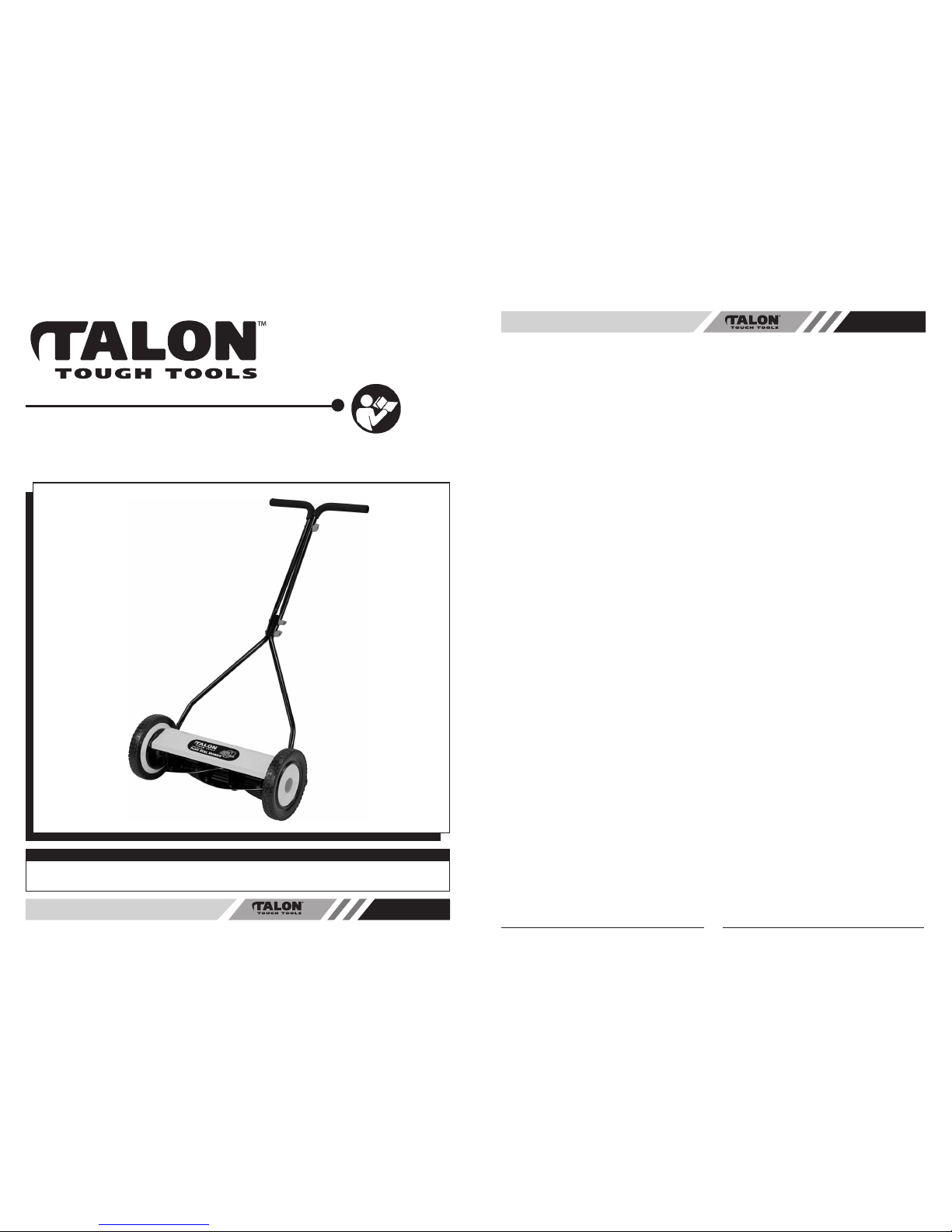
•HANDLE ASSEMBLY
1. Fasten the top of handle 1 and 2 by sliding the bolt
through both pieces at point C and tighten securely.
(See Fig. 1)
2. Repeat this process and tighten the bottom portion of
the upper handle 3 and 4 at point D and top portion at
point E.
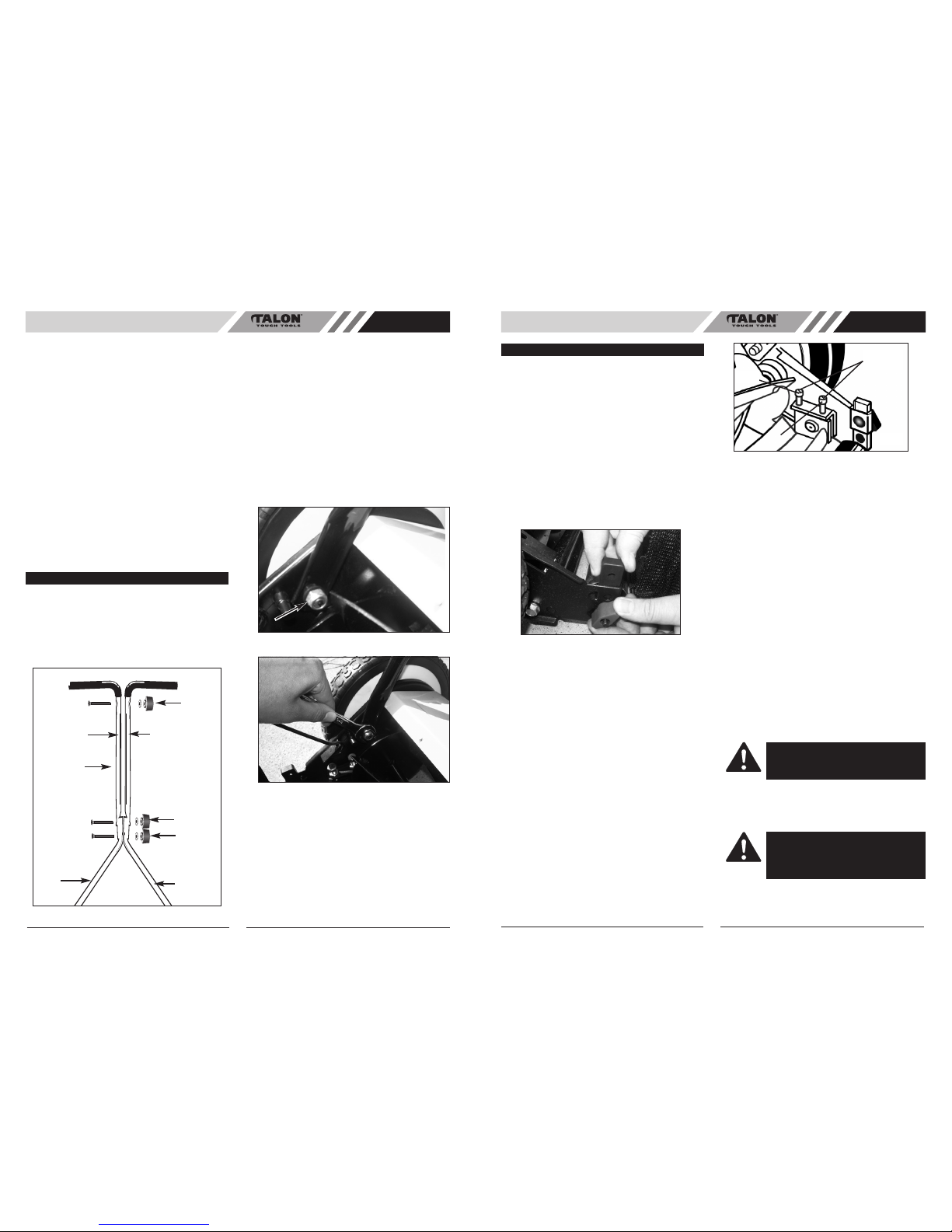
•
ATTACHING THE HANDLE TO THE
MOWER
• As you follow the instructions below, refer to Fig. 2A
& B for more information.
• After assembling the handle, fit the holes at the end
of the lower portion of the handle on the left and right
side, over the front (with threaded end) posts
extending out from the side plates.
• When the handle is in place over the posts, screw the
lock nuts and washers onto the posts on both sides
to prevent the handle from coming off. Tighten with
13mm Spanner (not supplied).
ASSEMBLY
Thank you for choosing our TALON garden tool. We are convincd that you will be satisfied with this low cost, no noise and no
pollution mower. Please read all instructions in this manual carefully before using mower.
1
Fig. 1
2
34
E
D
B
C
Fig. 3
AU
OPERATION
WARNING: Do not overtighten the adjust-
ing screws, as this could damage the cutter
bar. Both screws must be tight on the final
adjustment.
WARNING: Clean any grinding compound
or debris from the cutter bar blade, reel
blades, pinions and pawls. Lubricate axle
and pinion with a light film of wheel bearing
grease and replace wheels.
Fig. 2A
Fig. 2B