Toro ProPass 200 User manual

FormNo.3418-725RevA
ProPass200TopDresserwith
TwinSpinner
ModelNo.44701—SerialNo.401380001andUp
ModelNo.44751—SerialNo.401380001andUp
Registeratwww.Toro.com.
OriginalInstructions(EN)*3418-725*A

WARNING
CALIFORNIA
Proposition65Warning
ThisproductcontainsachemicalorchemicalsknowntotheStateofCalifornia
tocausecancer,birthdefects,orreproductiveharm.
ThisproductcomplieswithallrelevantEuropeandirectives,fordetailspleaseseetheseparateproductspecic
DeclarationofConformity(DOC)sheet.
ElectromagneticCompatibility
Domestic:ThisdevicecomplieswithFCCRulesPart15.
Operationissubjecttothefollowingtwoconditions:(1)This
devicemaynotcauseharmfulinterferenceand(2)thisdevice
mustacceptanyinterferencethatmaybereceived,including
interferencethatmaycauseundesirableoperation.
Thisequipmentgeneratesandusesradiofrequencyenergyand
ifnotinstalledandusedproperly,instrictaccordancewiththe
manufacturer'sinstructions,maycauseinterferencetoradio
andtelevisionreception.Ithasbeentypetestedandfoundto
complywithinthelimitsofaFCCClassBcomputingdevicein
accordancewiththespecicationsinSubpartJofPart15of
FCCRules,asstatedabove.However,thereisnoguarantee
thatinterferencewillnotoccurinaparticularinstallation.If
thisequipmentdoescauseinterferencetoradioortelevision
reception,whichcanbedeterminedbyturningtheequipmentoff
andon,theuserisencouragedtotrytocorrecttheinterference
byoneormoreofthefollowingmeasures:Reorientthereceiving
antenna,relocatetheremotecontrolreceiverwithrespecttothe
radio/TVantennaorplugthecontrollerintoadifferentoutletso
thatthecontrollerandradio/TVareondifferentbranchcircuits.If
necessary,theusershouldconsultthedealeroranexperienced
radio/televisiontechnicianforadditionalsuggestions.The
usermayndthefollowingbookletpreparedbytheFederal
CommunicationsCommissionhelpful:"HowtoIdentifyand
ResolveRadio-TVInterferenceProblems".Thisbookletis
availablefromtheU.S.GovernmentPrintingOfce,Washington,
DC20402.StockNo.004-000-00345-4.
FCCID:W7OMRF24J40MDME-Base,
OA3MRF24J40MA-HandHeld
IC:7693A-24J40MDME-Base,7693A-24J40MA-HandHeld
Operationissubjecttothefollowingtwoconditions:(1)this
devicemaynotcauseinterference,and(2)thisdevicemust
acceptanyinterference,includinginterferencethatmaycause
undesiredoperationofthedevice.
JapanElectromagneticCompatibilityCertication
Handheld:
RF2CAN:
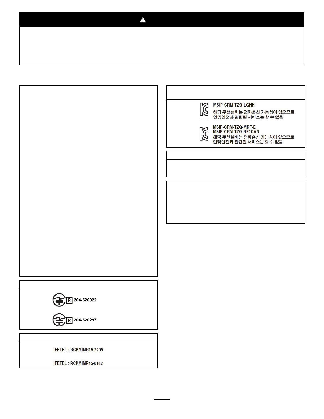
MexicoElectromagneticCompatibilityCertication
Handheld:
RF2CAN:
KoreaElectromagneticCompatibilityCertication(Decal
providedinseparatekit)
Handheld:
RF2CAN:
SingaporeElectromagneticCompatibilityCertication
Handheld:TWM240008_IDA_N4023-15
RF2CAN:TWM-240005_IDA_N4024-15
MoroccoElectromagneticCompatibilityCertication
AGREEPARL’ANRTMAROC
NUMEROd’agrement:MR14078ANRT2017
Delivred'agrement::29/05/2017
Introduction
Thismachineisintendedtobeusedbyprofessional,
hiredoperatorsincommercialapplications.Itis
designedprimarilyformeteringanddispersing
materials,underarangeofmoistureconditions,
withoutcloggingordrasticallyaffectingthedispersion.
Important:Tomaximizethesafety,performance,
andproperoperationofthismachine,carefully
readandfullyunderstandthecontentsofthis
Operator’sManual.Failingtofollowthese
operatinginstructionsortoreceiveproper
trainingmayresultininjury.Formoreinformation
onsafeoperatingpractices,includingsafetytips
andtrainingmaterials,gotowww.Toro.com.
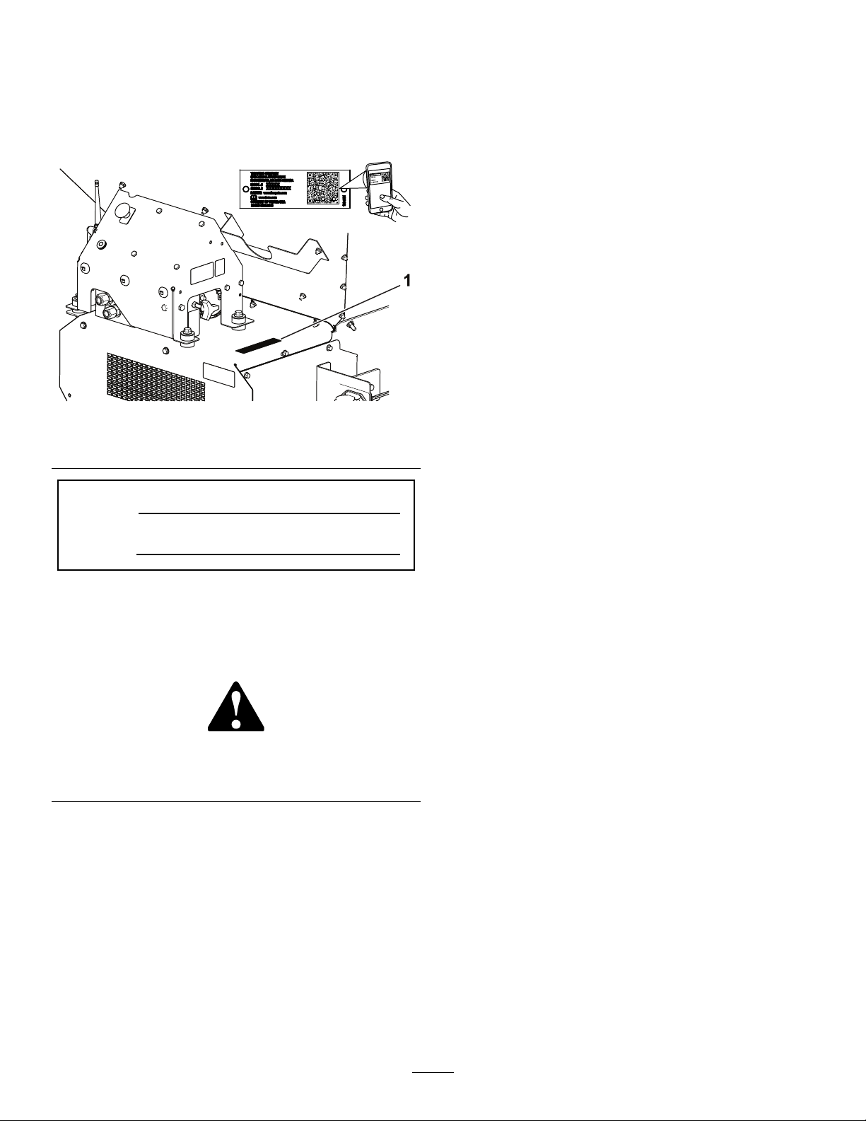
Wheneveryouneedservice,genuineT oroparts,or
additionalinformation,contactanAuthorizedService
DealerorToroCustomerServiceandhavethemodel
andserialnumbersofyourproductready.Figure1
identiesthelocationofthemodelandserialnumbers
©2017—TheToro®Company
8111LyndaleAvenueSouth
Bloomington,MN554202
Contactusatwww.Toro.com.
PrintedintheUSA
AllRightsReserved

ontheproduct.Writethenumbersinthespace
provided.
Important:Withyourmobiledevice,youcan
scantheQRcode(ifequipped)ontheserial
numberdecaltoaccesswarranty,parts,andother
productinformation.
g237535
Figure1
1.Modelandserialnumberlocation
ModelNo.
SerialNo.
Thismanualidentiespotentialhazardsandhas
safetymessagesidentiedbythesafety-alertsymbol
(Figure2),whichsignalsahazardthatmaycause
seriousinjuryordeathifyoudonotfollowthe
recommendedprecautions.
g000502
Figure2
1.Safety-alertsymbol
Thismanualuses2wordstohighlightinformation.
Importantcallsattentiontospecialmechanical
informationandNoteemphasizesgeneralinformation
worthyofspecialattention.
Contents
Safety.......................................................................4
GeneralSafety...................................................4
SafetyandInstructionalDecals..........................5
Setup........................................................................8
1SettingUptheMachineBaseModel
........................................................................9
2InstallingthePowerHarness..........................10
3InstallingtheHopperExtensionKit..................11
4MountingtheHoppertotheT ow
Chassis.........................................................12
5ConnectingtheIntermediateWire
Harness........................................................12
6ConnectingtheOn/OffPendant.....................13
7AssemblingtheHandheldRemote.................13
8MountingtheWirelessRemote......................14
ProductOverview...................................................15
Controls...........................................................15
Specications..................................................17
Attachments/Accessories.................................17
Operation................................................................18
BeforeOperationSafety...................................18
OperatingCharacteristics.................................18
ConnectingtheMachinetoaT ow
Vehicle..........................................................18
TurningtheMachinePowerOn/Off...................19
PreparingtheMachineforOperation................20
DuringOperationSafety...................................23
SlopeSafety.....................................................24
OperatingtheMachine.....................................24
WirelessControllerSafety(Model44751
only)..............................................................25
DisconnectingtheMachinefromaTow
Vehicle..........................................................25
OperatingtheHydraulicControlsand
Options.........................................................25
OperatingtheFloorandOption.........................31
SettingthePreset1,2,and3Buttons................33
UsingaPresetMode........................................34
ChoosingaT owVehicle....................................34
LoadingtheHopper..........................................34
UnloadingtheHopper.......................................34
Traveling...........................................................35
AfterOperationSafety......................................35
ParkingtheMachine.........................................35
UsingtheStorageStand...................................36
Maintenance...........................................................38
Pre-MaintenanceSafety...................................38
Lubrication........................................................38
DailyChecks....................................................39
HydraulicSystem.............................................39
MaintainingtheConveyorBeltSystem..............40
WashingtheMachine.......................................41
Storage...................................................................42
Troubleshooting......................................................43
CheckingFaultCodes(EHModels
Only).............................................................43
3

HandheldRemoteMessages(EHModels
Only).............................................................44Safety
GeneralSafety
Thisproductiscapableofcausingpersonalinjury.
Alwaysfollowallsafetyinstructionstoavoidserious
personalinjury.
Usingthisproductforpurposesotherthanitsintended
usecouldprovedangeroustoyouandbystanders.
•Readandunderstandthecontentsofboththis
Operator’sManualandtheoperator’smanualof
thetowvehiclebeforeusingthismachine.Ensure
thateveryoneusingthisproductknowshowtouse
thismachineandthetowvehicleandunderstands
thewarnings.
•Donotputyourhandsorfeetnearmoving
componentsofthemachine.
•Donotoperatethemachinewithoutallguards
andothersafetyprotectivedevicesinplaceand
workingonthemachine.
•Keepthemachineasafedistanceawayfrom
bystanderswhileitismoving.
•Keepchildrenoutoftheoperatingarea.Never
allowchildrentooperatethemachine.
•Stopthemachine,shutofftheengine,engagethe
parkingbrake,removethekey,andwaitforall
movingpartstostopbeforeservicing,fueling,or
uncloggingthemachine.
Improperlyusingormaintainingthismachinecan
resultininjury.Toreducethepotentialforinjury,
complywiththesesafetyinstructionsandalwayspay
attentiontothesafety-alertsymbol,whichmeans
Caution,Warning,orDanger—personalsafety
instruction.Failuretocomplywiththeseinstructions
mayresultinpersonalinjuryordeath.
Youcanndadditionalsafetyinformationwhere
neededthroughoutthismanual.
4

SafetyandInstructionalDecals
Safetydecalsandinstructionsareeasilyvisibletotheoperatorandarelocatednearanyarea
ofpotentialdanger.Replaceanydecalthatisdamagedormissing.
decal119-6809
119-6809
1.ReadtheOperator'sManualforinstructionsoncleaning
themachine.
decal119-6808
119-6808
1.Tailgateheightindicator
decal119-6818
119-6818
1.Tailgateadjustment
decal119-6854
119-6854
1.Floorspeed
decal119-6853
119-6853
1.Spinnerspeed
decal115-2047
115-2047
1.Warning—donottouchthehotsurface.
decal119-0217
119-0217
1.Warning—shutofftheengine;stayawayfrommovingparts;
keepallguardsandshieldsinplace.
5

decal119-6820
119-6820
1.Spinnerspeedadjustment
decal119-6855
119-6855
1.Spinnerspeed
decal119-6856
119-6856
1.Floorspeed
decal119-6804
119-6804
1.Thrownobjecthazard—keepbystandersasafedistance
fromthemachine.
decal119-6805
119-6805
1.Cutting/dismembermenthazard,impeller—stayawayfrom
movingparts,keepallguardsandshieldsinplace.
decal119-6810
119-6810
1.ReadtheOperator'sManual.
2.2peoplerequiredtolift.
decal119-6817
119-6817
1.Finetuningspinners
decal119-6816
119-6816
1.Slideadjustment
decal119-6815
119-6815
1.Floorspeedadjustment2.Spinnerspeedadjustment
6

decal119-6814
119-6814
1.Lightspreadspinneradjustmentsettings(refertothe
Operationsectionformoreinformation).
3.Warning—slideadjustmentandtailgateadjustment.
2.Heavyspreadspinneradjustmentsettings(refertothe
Operationsectionformoreinformation).
decal119-6806
119-6806
1.Warning—readtheOperator'sManual.4.Warning—shutofftheengine,removetheignitionkey,and
readtheOperator'sManualbeforeperformingmaintenance
onthemachine.
2.Warning—donotoperatethemachineunlessyouaretrained.5.Warning—noridersonthemachine
3.Thrownobjecthazard—keepbystandersasafedistancefrom
themachine.
6.Warning—stayawayfrommovingparts;keepallguardsand
shieldsinplace.
decal119-6819
119-6819
1.Spinnerspeedpercentage2.Beltspeedpercentage
decal131-6766
131-6766
1.7.5A3.Electricalaccessory—15A
2.7.5A4.TEC-2403—2A
7

Setup
LooseParts
Usethechartbelowtoverifythatallpartshavebeenshipped.
ProcedureDescriptionQty.Use
Hopperguard1
Buttonheadbolt(1/4x5/8inch)3
1Locknut3
Setupthemachinebasemodel.
Powerharness1
Socketbracket1
Socketbracket,heavy1
Carriagescrew2
Flangenut2
Screw2
2
Flangenut2
Installthepowerharness.
Hopperextension(front)1
Hopperextension(rear)1
Bolt9
3Flangenut9
Installthehopperextensionkit.
Bolt6
4Flangenut6Mountthehoppertothetowchassis.
5Intermediatewireharness1Connecttheintermediatewireharness.
6On/offpendant1Connecttheon/offpendant(Model
44701only).
Handheldremote1
AAbatteries4
Magneticbracket1
7Screws,small6
Assemblethehandheldremote(Model
44751only).
Controllermountassembly1
8Wirelessremoteassembly1
Mountthewirelessremote(Model
44751only).
MediaandAdditionalParts
DescriptionQty.Use
Operator’sManual1Readbeforeoperatingthemachine.
DeclarationofConformity1Ensureregulatorycompliance.
Note:Determinetheleftandrightsidesofthemachinefromthenormaloperatingposition.
8

1
SettingUptheMachine
BaseModel
Partsneededforthisprocedure:
1Hopperguard
3Buttonheadbolt(1/4x5/8inch)
3Locknut
Procedure
1.Removethebasemodelmachinefromthe
shippingcrate.
2.Attherearofthetwinspinner,removethebolt
andnutattachingthemachineliftingdevice
shippingbrackettothetwinspinner(Figure3).
g013203
Figure3
1.Shippingbracket
3.Atthefrontofthetwinspinner,removethe2
boltsandnutsattachingthemachinelifting
deviceshippingbrackettotheTwinSpinner
(Figure4).
g013204
Figure4
1.Shippingbracket
4.Liftthetwinspinneroutofthehopperusingthe
twinspinneroutergrabhandlesandplacethe
twinspinnerunitontheground(Figure5).
Note:Thissteprequires2people.
g013205
Figure5
1.Twinspinner
5.Removethe4screwsfromthelegsofthetwin
spinner.Withthehelpofapartner,liftthetwin
spinnerandremovethepackingstudsand
packingfoam(Figure6).
9

g013207
Figure6
1.Packingstudsandfoam
6.Installthehopperguardusingthesupplied
button-headbolts(1/4x5/8inch)andnylon
locknuts(Figure7).
g030044
Figure7
1.Hopperfrontguard2.Bolts
2
InstallingthePower
Harness
Partsneededforthisprocedure:
1Powerharness
1Socketbracket
1Socketbracket,heavy
2Carriagescrew
2Flangenut
2Screw
2Flangenut
Procedure
Thetowvehiclepowerharnessprovidestheelectrical
powerrequiredbythecontrolsystemsofthemachine.
Installthisharnessonthevehicleyouplantouse
tooperatethemachine.Ifyouwillusemorethan1
vehiclewiththemachine,purchaseadditionalpower
harnessesfromyourTorodistributor.
1.Mountthesocketbrackettoaxedpointatthe
rearofthetowvehicleusing1ofthemounting
bracketsprovided(Figure8).
Note:Ensurethatthebracketwillnotcome
incontactwithanythingifthetowvehicleis
equippedwithadumpbox.
Important:Ensurethatnoneofthewiring
islooseorinthewayofanymechanical
components.
10

g013261
Figure8
1.Socketbracket
2.Routeandsecuretheelectricalwiringfromthe
batterytotheelectricalplugbracket(Figure9).
g013262
Figure9
1.Whitewire(brass)3.Nowire(brass)
2.Nowiresilver(silver)4.Blackwire(brass)
3.Feedthewiringthroughthesocketbracketand
installtheblackrubbergrommetoverthewiring
(Figure9).
4.Boltthesockettothesocketbracketusingthe
bolts(1/4inch).
5.Connecttheredwire(power)tothepositive
postonthebattery,thenconnecttheblackwire
(ground)tothenegativepostonthebattery.
3
InstallingtheHopper
ExtensionKit
Partsneededforthisprocedure:
1Hopperextension(front)
1Hopperextension(rear)
9Bolt
9Flangenut
Procedure
1.Removethehopperextensionsfromthebox
andidentifythefrontandtherear(Figure10
andFigure11).
g013263
Figure10
1.Fronthopperextension(showingholeorientation)
g013264
Figure11
1.Rearhopperextension(showingholeorientation)
2.Usingthehardwareprovided,attachthehopper
extensionstothehopper.Placethenutsonthe
outsideofthehopper.
11

g237533
Figure12
Hopperextensionkitinstalled
4
MountingtheHoppertothe
TowChassis
TowChassisCongurationOnly
Partsneededforthisprocedure:
6Bolt
6Flangenut
Procedure
Note:IfyouaremountingtheProPasstopdresser
ontosomethingotherthanthetowchassis,referto
theinstallationinstructionsforyourapplication.
1.Attachaliftingdevicetotheliftingbracketbolted
insidethehopperassembly(Figure13).
g013209
Figure13
1.Liftingbracket
WARNING
Donotattempttoliftthebedandhopper
withtheTow-BehindChassis,ProGator,
Workman,orTDCChassisconnected.
Theliftingbracketisnotcapableoflifting
theentiremachine.
2.Usingaliftingmechanism,positionthehopper
overthetowchassis.
3.Lineupthe6mountingholes(3perside)and
installthe5/16x1inchboltsandangenuts.
g013949
Figure14
1.Mountinglocations(3eachside)
4.Removetheliftingbracketfromthehoppersides
andinstalltheboltstothehoppersides.
Note:Retaintheliftingbracketforfutureuse;
donotdiscardit.
12

5
Connectingthe
IntermediateWireHarness
Partsneededforthisprocedure:
1Intermediatewireharness
Procedure
Plugtheintermediatewireharnessintothepower
harnessconnectoronthemachine(Figure15or
Figure16).
g237534
Figure15
Model44751
1.Powerharness2.Intermediatewireharness
g013948
Figure16
Model44701
1.Powerharness2.Intermediatewireharness
6
ConnectingtheOn/Off
Pendant
Model44701Only
Partsneededforthisprocedure:
1On/offpendant
Procedure
Plugtheon/offpendantconnectorintotheconnector
onthemachine(Figure17).
g013947
Figure17
1.On/offpendant
13

7
AssemblingtheHandheld
Remote
Model44751Only
Partsneededforthisprocedure:
1Handheldremote
4AAbatteries
1Magneticbracket
6Screws,small
Procedure
1.Removetherubberbandssecuringtheremote
halvestogether,andremovethebackcover.
2.Installthebatteriesintotheterminalcradle
observingproperpolarity.(Ifthebatteries
areimproperlyinstalled,theunitwillnotbe
damaged,butitwillfailtooperate.)Thecradle
isembossedwithpolaritymarkingsforeach
terminal(Figure18).
g028875
Figure18
1.Rubberseal3.Handheldremote
2.Steelgasket4.4AAbatteries
3.Ensurethatthesteelgasketandrubbersealare
seatedinthechannelintheremoteandsetthe
backcoverinplace(Figure18).
4.Securethecoverwith6screws(Figure18)and
torquethemto1.5to1.7N∙m(13to15in-lb).
5.Installthehandheldremoteintothemagnetic
remotebracket,slidethehalvestogetherto
securetheremote,andtightentheboltinthe
magnet(Figure19).
g028874
Figure19
1.Handheldremote3.Boltinthemagnet
2.Magneticremotebracket
8
MountingtheWireless
Remote
Model44751Only
Partsneededforthisprocedure:
1Controllermountassembly
1Wirelessremoteassembly
Procedure
Insertthecontrollermountassemblyintoacupholder
orsimilaropeningonthetowvehicleandusetostore
wirelessremote.Also,thewirelessremotemagnet
willsticktoanymetalcomponent.
14

g030466
Figure20
WorkmanHeavyDutyVehicleShown
1.Remote2.Controllermountassembly
ProductOverview
Controls
FlowControlValveforFloor
Model44701Only
Ahydraulicowcontrolvalvecontrolsthespeedof
theconveyorbelt.
Thehighestspeedsettingis10andistypicalformost
applicationsfoundontheColor-CodedOperation
Systemdecals.Uselowersettingsforverylight
applications.
g013344
Figure21
1.Floorcontrolvalve
FlowControlValveforOptions
Model44701Only
g013345
Figure22
1.Optioncontrolvalve
15

Ahydraulicowcontrolvalvecontrolsthespeedof
theoption(TwinSpinner).Thespinnericonindicates
thespeedpercentageforthewirelesscontroller
only—forstandardhydraulics,placethecontrolinthe
appropriatecolorarea,startingatthedottedlineand
adjustspeedswithinthecolorzoneasrequired.
On/OffPendant
Model44701Only
Usethe2switchesontheOn/Offpendanttorunthe
conveyorbeltortheoption(Figure23).Keepthe
On/Offpendantwithinreachoftheoperator.
g013346
Figure23
1.On/offpendant
E-StopButton
Model44751Only
Whennishedworkingwiththemachine,always
presstheE-STOPbutton(Figure24)todisablethe
electricalsystem.Whenbeginningworkwiththe
machineyoumustpulltheE-STOPbuttonbackout
beforeturningonthehandheldremote.
g237530
Figure24
1.E-STOPButton
DiagnosticLEDFunction
AfterpullinguptheE-STOPbutton,thediagnostic
LED(Figure25)willilluminateandremainonfor5
seconds,turnofffor5seconds,andthenwillbegin
ashingat3Hz(3ashesasecond)untilyouturnthe
handheldremoteon.Ifthelightturnsonfor5seconds
andthenstartsblinkingat10Hz(withorwithouta5
secondpause),thereisafaultwiththemachine;refer
toCheckingFaultCodes(EHModelsOnly)(page43).
Note:Ifyouhadthehandheldremoteonwhenyou
pulleduptheE-STOPbutton,thelightwillnotash
at3Hz(3ashespersecond)afterturningofffor5
seconds.
g237532
Figure25
1.DiagnosticLED
16

HandheldRemote
Model44751Only
g029772
Figure26
1.LCDdisplay10.FloorStart
2.RemotestatusLED11.FloorStop
3.AllStart:StartsFloorand
Option
12.DecreaseFloorSpeed
4.On/Off13.IncreaseFloorSpeed
5.Store:SavesPreset
Settings
14.OptionStart
6.Preset115.OptionStop
7.Preset216.IncreaseOptionSpeed
8.Preset317.DecreaseOptionSpeed
9.AllStop:Stopsall
functions
Specications
Weights
BaseModel248kg(546lb)
TwinSpinner68kg(150lb)
Radio
Frequency2.4GHz
MaxOutputPower19.59dBm
Attachments/Accessories
AselectionofT oroapprovedattachmentsand
accessoriesisavailableforusewiththemachineto
enhanceandexpanditscapabilities.Contactyour
AuthorizedServiceDealerorDistributororgoto
www.T oro.comforalistofallapprovedattachments
andaccessories.
Tobestprotectyourinvestmentandmaintainoptimal
performanceofyourToroequipment,countonT oro
genuineparts.Whenitcomestoreliability,T oro
deliversreplacementpartsdesignedtotheexact
engineeringspecicationofourequipment.Forpeace
ofmind,insistonT orogenuineparts.
17

Operation
BeforeOperationSafety
•Themachinehasdifferentbalance,weight,and
handlingcharacteristicscomparedtosomeother
typesoftowedequipment.Readandunderstand
thecontentsofthisOperator'sManualbefore
operatingthemachine.Becomefamiliarwithall
controlsandknowhowtostopquickly.
•Neverallowchildrenoruntrainedpeopleto
operateorservicethemachine.Localregulations
mayrestricttheageoftheoperator.Theowner
isresponsiblefortrainingalloperatorsand
mechanics.
•Becomefamiliarwiththesafeoperationofthe
equipment,operatorcontrols,andsafetysigns.
•Knowhowtostopthemachineandshutoffthe
enginequickly.
•Checkthatoperator-presencecontrols,safety
switches,andshieldsareattachedandfunctioning
properly.Donotoperatethemachineunlessthey
arefunctioningproperly.
•Keepallshieldsandsafetydevicesinplace.If
ashield,safetydevice,ordecalisillegibleor
missing,repairorreplaceitbeforeoperatingthe
machine.
•Tightenanyloosenuts,bolts,andscrewsto
ensurethatthemachineisinsafeoperating
condition.Ensurethatthemachinecomponents
areinplaceandsecure.
•Ensurethatyourtractorissuitableforusewithan
implementofthisweightbycheckingwithyour
tractorsupplierormanufacturer.
•Stoptheengineandwaitforallmovingparts
tostopbeforemakinganyadjustmentstothe
machine.
OperatingCharacteristics
Themachinehasbalance,weight,andhandling
characteristicsthatmaybedifferentfromothertypes
ofpulledequipment.ReadthisOperator’sManual
carefully.
Withanoptionmounted,beawareoftheground
clearancewhentravelingonhills.Foramachine
mountedonatow-behindchassis,theground
clearanceis13inches(33cm)unloaded.Fora
machinemountedonaTrucksterdirectconnect
chassis,thegroundclearanceis17inches(43cm)
unloaded.
Important:Beforeloadingthemachineonoroff
ofatrailer,removetheoptiontoavoiddamaging
it.
ConnectingtheMachineto
aTowVehicle
WARNING
Standingbetweenthemachineandthe
towvehicleduringcouplingcouldresultin
seriousinjury.
Donotstandbetweenthemachineandthe
towvehicleduringcoupling.
1.Adjustthehitchheightbyturningthejackstand
handle(s)tokeepthemachinelevel.
2.Connecttheclevis-stylehitchofthemachine
tothetowvehicleusinga18mm(3/4inch)
diametersafetyapprovedhitchpinandsafety
clip(notsupplied).Installthehitchpinthrough
themachinehitchandthetow-vehicledraw
baronthetow-behindchassisorthrough
thesuppliedhitchmountonTrucksterdirect
connect.
3.Lowerthehitchusingthejackstand(s).
4.Whenthefullweightofthemachinehasbeen
transferredtothetow-vehicledrawbarfrom
thejackstand(s),pullthepinholdingthejack
stand(s)inplace.
5.Storethejackstand(s)asfollows:
•Ontow-behindchassisturnthejackstand90
degreescounter-clockwiseuntilthebottom
ofthejackstandpointstotherearofthe
machine.Thisisthetravelingposition.
•OnTrucksterdirectconnectchassismove
thejackstandstotherearofthemachine
andturnthem90degreesuntilthebottomof
bothjackstandspointstothecenterofthe
machine.Thisisthetravelingposition
6.Attachthepressurehoseandthereturnhoseto
thecorrecthydraulicoutputsonthetowvehicle.
Thereturnhosehasaninlinecheckvalve.If
youreversethehoses,somemachinefunctions
mayrunbackwardsornotworkatall.T estthe
hydraulicsbeforeoperatingthemachineforthe
rsttime.
Important:Donotallowthehydrauliclines,
thepowercable,andthependantcablesto
dragontheground.Avoidlocationswhere
theycouldbecomepinchedorcut.
7.Plugtheintermediatewireharnessintothetow
vehiclepowerconnector.
8.Checkthelevelofthehydraulicuidinthetank
andaddmoretollit,ifnecessary;refertothe
towvehicle’sowner’smanual.
18

TurningtheMachinePower
On/Off
Whennishedworkingwiththemachine,always
presstheE-STOPbutton(Figure27)todisablethe
electricalsystem.Whenbeginningworkwiththe
machine,youmustpulltheE-STOPbuttonbackout
beforeturningonthehandheldremote.
g237530
Figure27
1.E-STOPButton
Important:Whendoneoperatingthemachine,
presstheE-STOPbuttontopreventthetowvehicle
batteryfrombeingdischarged.
19

PreparingtheMachinefor
Operation
Themachinefeaturesauniquecolor-codedoperationsystemthattakestheguess-workoutofsettingupyour
machine.Simplychoosethespread,identifythecolor,andthenadjusteachsettingtomatchthatcolorto
getaperfectspreadeverytime.
ChoosingtheSpread
Choosethespreadbyreadingthemainoperationdecalfoundonthetailgateofthemachine(Figure28).
decal119-6814
Figure28
1.Lightspreadspinneradjustmentsettings3.Warning—slideadjustmentandtailgateadjustment
2.Heavyspreadspinneradjustmentsettings
g013715
Figure29
Thisdecalshowstherangeofspreadsavailableandclassiesthembycolor(Figure29).Eachcolorrepresents
adifferentrateofapplicationfromUltra-LightthroughUltra-Heavy.Thespreaddensityisindicatedbythe
shadedovals(lightthroughheavy).Theapproximatewidthisalsoindicated
CheckingtheBlades
Note:Themachineisshippedwiththespinner
bladesinPOSITIONB.
Thelighterspreads(bluepanel)remindyoutoensure
thatthespinnerbladesareinPOSITIONA(Figure30).
g013716
Figure30
WhenthebladesareinPOSITIONA,theinsidebolts
(closesttothecenterofthedisc)aretighttothe
bladewallandtheoutsidebolts(closesttothe
edgeofthedisc)areawayfromthebladewall.
Thisiscriticalasthispositionisengineeredtogive
theoptimumspreadanddistributionathighspeeds
andlowsandvolume.
Forheaviersettings(goldpanel)thebladesshouldbe
inPOSITIONBtoprovidethebestdistributionathigher
volumesandslowerdiscspeeds(Figure31).
g013717
Figure31
WhenthebladesareinPOSITIONB,theinsidebolts
(closesttothecenterofthedisc)areawayfrom
thebladewallandtheoutsidebolts(closesttothe
edgeofthedisc)aretighttothebladewall.
Important:Incorrectbladepositionisacommon
reasonthatspreadpatternsfail.
20
Other manuals for ProPass 200
3
This manual suits for next models
2
Table of contents
Other Toro Lawn Mower manuals

Toro
Toro 414300000 User manual

Toro
Toro TimeCutter SW 4200 User manual

Toro
Toro Reelmaster 4000-D 03706 User manual

Toro
Toro 72902TE User manual

Toro
Toro 16401 User manual

Toro
Toro Titan Z4800 User manual

Toro
Toro 30799 User manual

Toro
Toro 20197 User manual

Toro
Toro 21864 User manual

Toro
Toro XLS 380 Manual