Talon EG500 User manual

Generator Owners Manual
Safety
Operation
Assembly
Maintenance
Model No. EG600W
For your own safety please read this manual before attempting to operate your
new unit. Failure to follow instructions can result in serious personal injury. Spend
a few moments to familiarise yourself with your generator before each use. Keep
this manual as reference for operation and maintenance of your generator.
Model No. EG500
WARNING - PLEASE READ
Talon Manual_EG500+EG600W_v3.qxp 23/05/2006 4:26 PM Page 1

2
This manual covers the operation and maintenance of Talon generators. Please read and understand
this manual before using your new generator. If assistance is required, please contact Talon Tools
Australia or any Talon Tools Authorised Servicing Dealer.
To emphasise special information the DANGER, WARNING and CAUTION icons are used, please
observe these carefully.
Congratulations on your purchase of a quality Talon product.
INTRODUCTION
1
WARRANTY INFORMATION
Personal injury or death will result if information is disregarded.
Personal injury may result if information is disregarded.
Follow instructions to avoid generator damage and possible loss of warranty.
WARRANTY...................................................................................................................... 1
INTRODUCTION............................................................................................................... 2
SPECIFICATIONS............................................................................................................ 3
IDENTIFICATION............................................................................................................. 4
SAFETY INSTRUCTIONS................................................................................................ 5
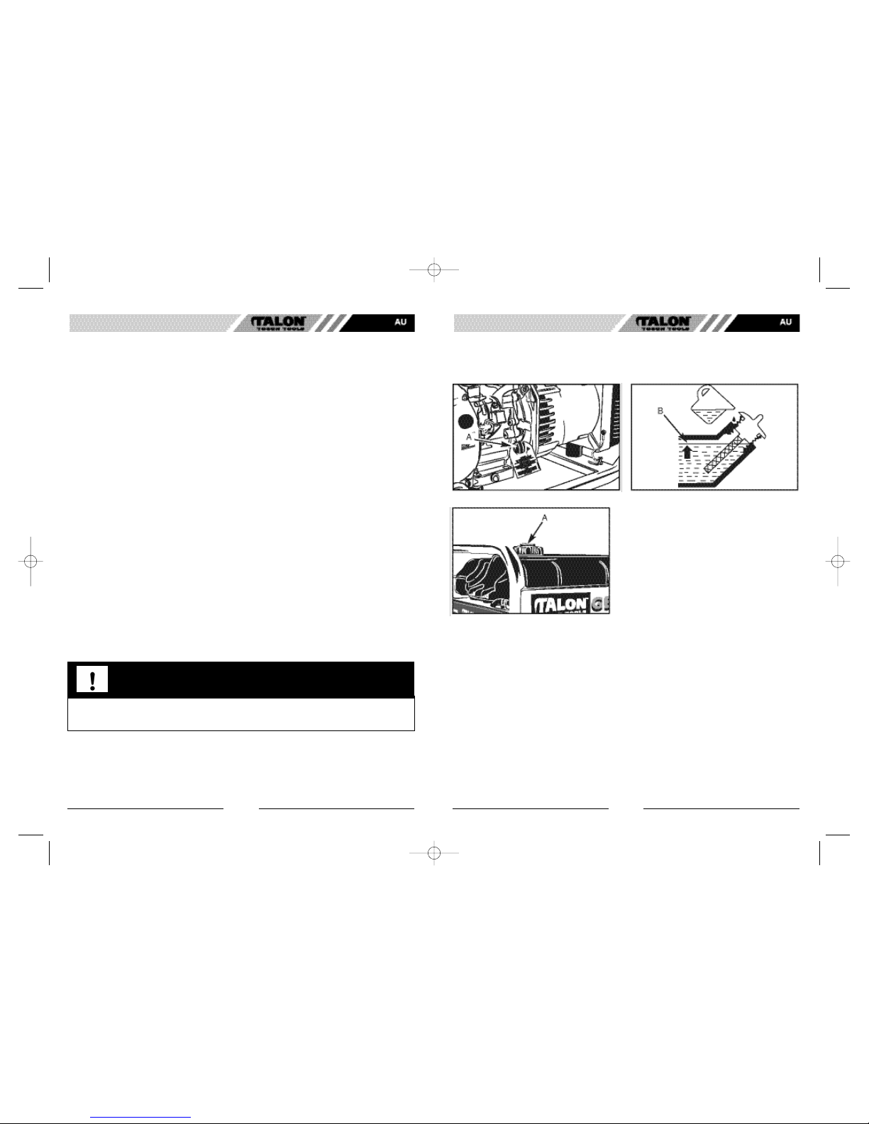
FUEL AND LUBRICATION............................................................................................... 7
OPERATION..................................................................................................................... 9
POWER USAGE............................................................................................................... 13
MAINTENANCE............................................................................................................... 14
TRANSPORT/ STORAGE................................................................................................ 18
TROUBLESHOOTING...................................................................................................... 20
WHEEL AND HANDLE KIT (OPTIONAL)....................................................................... 21
WIRING DIAGRAM........................................................................................................... 23
INDEX
DANGER
WARNING
CAUTION
The benefits conferred by this warranty are in addition to all other conditions and warranties in respect
of this product which the consumer may have under the Trade Practices Act 1974 or by any legislation of
a State or Territory of Australia. This product is warranted by Talon Tools Australia (ABN 12 099 520 939)
(The "Company") to be free from defects in material and workmanship for a period of 6 months from the
date of original purchase (for use in commercial applications) and 24 months (for home use). The
Company during the period of the warranty, will at its option, and subject to the conditions stated herein,
repair or replace without charge this product or any component part, which upon examination by an
Authorised Service Agent or by the Company is found to be defective.
Warranty Conditions
This warranty will not apply:
(i) where this product has been subjected to misuse, abuse, accident or want of care;
(ii) where this product has been used for a purpose for which it was not designed or suited.
(iii) where the service of this product has been undertaken by a person not authorised by the Company
to carry out such work or where parts have not been approved by the Company have been used.
Should service become necessary during the warranty period, the purchaser should contact an Authorised
Service Agent or the Company. In order to obtain warranty service, the purchaser must present the store
receipt showing the name of the retailer and the date of purchase together with a completed Warranty card.
The period of warranty begins from the original date of purchase, notwithstanding any subsequent repair
or parts replacement. No additional warranty or guarantee other than set out in this document, whether
written or verbal, is authorised to be made on the Company's behalf. The purchaser shall be responsible
for delivery or causing the product to be delivered to the Company or the Authorised Service Agent and
the purchaser shall be responsible for all charges in connection with the re-delivery of the product and/
or the delivery of parts. Damage in transit is not covered by this warranty and purchasers should remove
from the product any liquids (if applicable) before sending and pack the product securely to prevent damage.
Warranty Exclusions
Normal wear parts or components are subject to separate terms as follows: Normal wear parts, components
or service required when performing normal and regular maintenance of this product are not covered by
warranty unless it is found to be defective by an Authorised Service Agent or by the Company. Normal
wear parts include, but are not limited to:
LubricantsAir Filters Carburettor Tune-Ups
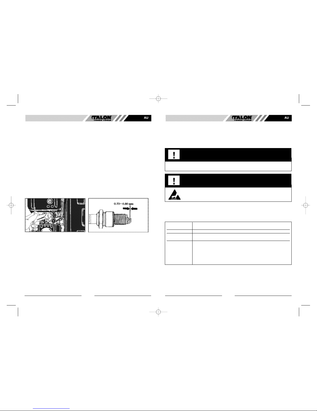
Spark Plugs Fuel Filters
Returns based on the above listed normal wear parts will not be accepted under this warranty as they are
considered consumable items and are at the expense of the purchaser.
LANDSCAPER PROFESSIONAL SERIES
GENERATOR 6 MONTH COMMERCIAL
WARRANTY
Talon Manual_EG500+EG600W_v3.qxp 23/05/2006 4:26 PM Page 1

4
GENERAL IDENTIFICATION
3
Model No EG500 EG600W
GENERAL FEATURES
Rated Power................................................... 3800 Watts...................................... 4360 Watts
Maximum Power............................................. 4180 Watts...................................... 4800 Watts
Emergency nominal power............................. 4.18 kVA.......................................... 4.8 kVA
Continue nominal power................................. 3.80 kVA.......................................... 4.36kVA
Power factor.................................................... 0.9 p.f.............................................. 0.9 p.f.
Nominal voltage.............................................. 240V................................................ 240V
Nominal frequency.......................................... 50 Hz............................................... 50 Hz
Alternator connections.................................... Single phase - Dual outlet............... Single phase - Dual outlet
ENGINE
Brand.............................................................. Talon................................................ Talon
Model.............................................................. 177F................................................. 182F
Stroke............................................................. 4 cycle............................................. 4 cycle
Cubic c.c......................................................... 270cc............................................... 338cc
Cooling system............................................... Air.................................................... Air
Starting system............................................... Recoil.............................................. Recoil
RPM................................................................ 3000 rpm......................................... 3000 rpm
Continuous power........................................... 5.4 KW............................................. 6.1KW
Max. power..................................................... 6.3 KW............................................. 7.1KW
Oil Capacity..................................................... 1.1 Litres.......................................... 1.1 Litres
Fuel Consumption 1/2 load.............................. 1.3 Litres/hr...................................... 1.3 Litres/hr
ALTERNATOR
Model.............................................................. GSA-L1-2 ....................................... GSA-L3-2
No. of Poles.................................................... 2...................................................... 2
Rotation Speed............................................... 3000 rpm......................................... 3000 rpm
Voltage............................................................ 240V................................................ 240V
Frequency....................................................... 50 Hz............................................... 50 Hz
Nominal power................................................ 4.18 kVA.......................................... 4.8kVA
Power factor.................................................... 0.9 p.f.............................................. 0.9 p.f.
Active power................................................... 3.8 kVA............................................ 4.36 kVA
Voltage System Regulation............................ Capacitor......................................... Capacitor
OVERALL DIMENSIONS AND WEIGHT (excluding wheel kit)
Length............................................................. 764mm............................................ 764mm
Width............................................................... 534mm............................................ 534mm
Height............................................................. 565mm............................................ 565mm
Weight............................................................ 64kg................................................. 84 Kg (incl. wheel kit)
Fuel Tank Capacity......................................... 19.0 Litres........................................ 19.0 Litres
Noise level...................................................... 80 db SPL-A.................................... 80 db SPL-A
WHEEL AND HANDLE KIT..................... Optional........................................... Supplied
MININUM CABLE SIZE:
Sec 1.5mm2 maximum length not exceeding 60mt.
Sec 2.5mm2 for length exceeding 60m and not exceeding 100m.
SPECIFICATIONS
1. Choke Lever
2. Fuel Control
3. ON/OFF Switch
4. Air Cleaner
5. Starter Handle
6. Oil Drain Plug
7. Oil Filler Cap/Dipstick
Figure 1
8. Ground Terminal
9. Power Outlets
10. Thermal Overload Switch
11. Fuel Tank Cap
12. Handles (Optional for EG500)
13. Wheels (Optional for EG500)
SPECIFICATIONS IDENTIFICATION
Talon Manual_EG500+EG600W_v3.qxp 23/05/2006 4:26 PM Page 3

6
SAFETY INSTRUCTIONS
5
SAFETY INSTRUCTIONS
Talon generators are designed to give safe and dependable service if operated according to instructions.
Read and understand this user manual before operating your generator. You can help prevent accidents
by being familiar with your generator's controls, and by observing safe operating procedures.
Operator Responsibility
1. Know how to stop the generator quickly in case of emergency.
2. Understand the use of all generator controls, output receptacles, and connections.
3. Be sure that anyone who operates the generator receives proper instruction. Do not let
children operate the generator without parental supervision. Always keep children away
from the generator.
Carbon Monoxide Hazards
PLEASE READ AND SAVE THESE
INSTRUCTIONS
Safety Information
Electric Shock Hazards
DANGER TOXIC FUMES
1. Exhaust contains poisonous carbon monoxide, a colorless and odorless gas.
Breathing exhaust can cause loss of consciousness and may lead to death.
2. Do not operate the generator in an enclosed space.
3. Ensure generator is positioned in a well-ventilated open area.
DANGER ELECTRIC SHOCK
1. The generator produces enough electric power to cause a serious shock or
electrocution if misused.
2. Using a generator or electrical appliance in wet conditions, such as rain or snow,
or near a pool or sprinkler system, or when your hands are wet, could result in
electrocution. Keep the generator dry. Do not use generator in the rain.
3. Do not store the generator unprotected outdoors.
4. Do not connect to a building's electrical system unless an isolation switch has
been installed by a qualified electrician.
Gasoline is extremely flammable and is explosive under certain conditions.
Refuel in a well-ventilated area with the engine stopped. Do not smoke or allow flames
or sparks in the area where the engine is refueled or where gasoline is stored.
Do not overfill the fuel tank (there should be no fuel in the filler neck). After refueling,
make sure the tank cap is closed properly and securely. Be careful not to spill fuel
when refueling. Spilled fuel or fuel vapour may ignite. If any fuel is spilled, make sure
the area is dry before starting the engine.
Avoid repeated or prolonged contact with skin or breathing of vapour.
AVOID FIRE
EXPLOSIONS CAN CAUSE SEVERE BURNS
HOT SURFACES
Do not connect to a building's electrical system unless an isolation switch has been installed by a
qualified electrician.
Refuelling
CAUTION
WARNING FIRE AND BURN HAZARDS
WARNING
Talon Manual_EG500+EG600W_v3.qxp 23/05/2006 4:26 PM Page 5

87
1. The exhaust system gets hot enough to ignite some materials.
-Keep the generator at least 1 metre (3 feet) away from buildings and other equipment during operation.
- Do not enclose the generator in any structure.
- Keep flammable materials away from the generator.
2. The muffler becomes very hot during operation and remains hot for a while after stopping the
engine. Be careful not to touch the muffler while it is hot. Let the engine cool before storing the
generator indoors.
3. Ensure the generator is on a flat, stable surface. Avoid tipping the unit over as this will spill fuel
from the fuel cap vent.
4. Do not operate the generator while on a moving platform.
Transport
1. Empty fuel tank before transporting unit.
2. Disconnect spark plug lead.
Adjustment or Maintenance
1. Empty fuel tank and ensure fuel control is switched off.
2. Disconnect spark plug lead.
Run-In Period:
Note: The engine will consume oil during the first 25 hours of operation. Check oil regularly during this
period.
Fuel Level
1. Check the fuel level. Remove the fuel tank
cap (A). (See Fig. 3)
2. Refill the tank if the fuel level is low. Do not
fill to top: Leave some space for fuel expansion.
Fuel Recommendation
NOTE: Fuel tank capacity of model EG400 is 11.6 litres.
1. Use unleaded gasoline with a minimum pump octane rating of 91.
2. We recommend unleaded gasoline because it produces fewer engine and spark plug deposits
and extends exhaust system life.
3. Never use stale or contaminated gasoline or oil/gasoline mixture. Avoid getting dirt or water in
the fuel tank.
4. Occasionally you may hear light "spark knock" or "pinging" (metallic rapping noise) while operating
under heavy loads. This is no cause for concern.
5. If spark knock or pinging occurs at a steady engine speed, under normal load, change brands
of gasoline. If spark knock or pinging persists, see an authorized Talon servicing dealer.
Figure 2A Figure 2B
Operating
Engine oil is a major factor affecting engine performance and service life. Follow
lubrication instructions carefully.
Engine oil
FUEL AND LUBRICATION
Figure 3
1. Gasoline is extremely flammable and is explosive under certain conditions. Do not smoke or allow
flames or sparks where the generator is refueled or where gasoline is stored. Refuel in a well
ventilated area with the engine stopped.
2. Fuel vapours are extremely flammable and may ignite after the engine has started. Make sure that
any spilled fuel has been wiped up before starting the generator.
3. Do not overfill the fuel tank. Allow space for fuel and vapour expansion.
Refuelling
SAFETY/ FUEL + LUBRICATION FUEL + LUBRICATION
CAUTION
SAE 10W-30 is recommended for general, all-temperature use.
1. Remove the oil filler cap (A) and wipe the dipstick clean. (See Fig. 2A)
2. Check the oil level (B) by inserting the dipstick into the filler neck without screwing it in.
(See Fig 2B)
3. If the level is low, fill to the top of the oil filler neck with the recommended oil.
Talon Manual_EG500+EG600W_v3.qxp 23/05/2006 4:26 PM Page 7

109
Generator Operation
Low Oil Engine Cut Off
The low oil engine cut off system is designed to prevent engine damage caused by an insufficient amount
of oil in the crankcase. Before the oil level in the crankcase can fall below a safe limit, the cut off system
will automatically shut down the engine (the engine switch will remain in the ON position).
Thermal Overload Switch
The thermal overload switch (A) will automatically switch OFF if there is a short circuit or a significant
overload of the generator at the receptacle. If the overload is switched OFF automatically, check that the
appliance is working properly and does not exceed the rated load capacity of the generator before switch-
ing the overload switch ON again. (See Fig 5A).
Ground Terminal (Earth)
The generator ground terminal (B) is connected to the frame of the generator, the metal non-current carry-
ing parts of the generator, and the ground terminals of each receptacle. (See Fig 5B).
Connection to a Buildings Electrical System
Connections for standby power to a building's electrical system must be made by a qualified electrician.
The connection must isolate the generator power from utility power, and must comply with all applicable
laws and electrical codes.
OPERATING INSTRUCTIONS
Before Starting
1. Check the engine oil level and top-up if necessary.
2. Check fuel level and top-up if necessary.
3. Ensure all appliances are switched off and disconnected from the generator.
4. Ensure thermal overload switch is "ON".
5. Check for any loose wires or damaged components which may prevent starting.
Engine Starting
1. Ignition Switch - (A) (See Figure 4A)
OFF: To stop the engine
ON: To start and run the engine
Turn switch to "ON" to start.
2. Fuel Control - (B) (See Figure 4B)
OFF: Stops fuel flowing from the tank to the engine.
ON: Allows fuel to flow into the carburetor.
Turn Fuel Control to "ON" to start.
3. Choke Lever - (C) (See Figure 4B)
START: Changes the fuel/air mixture to make cold starting easier.
RUN: After starting move choke lever to run for correct fuel mixture.
Move choke lever to start. After the engine starts and warms for 30 seconds, move choke lever to "RUN".
4. Recoil Starter - (D) (See Figure 4A)
i) Pull starter handle lightly until resistance is felt.
ii) Pull rope briskly to start engine.
iii) Do not allow rope to snap back against engine, this will damage the starter, the rope and the engine.
Engine Starting Summary
1. Check engine oil level.
2. On/Off switch to "ON".
3. Fuel control to "ON".
4. Choke lever to "START".
5. Pull recoil starter briskly after resistance is felt.
6. Move choke lever to run after 30 second warm up.
Stopping the Engine
In an emergency:
1. To stop the engine in an emergency, turn the engine switch to the OFF position.
In normal use:
1. Disconnect all electrical loads from power receptacles.
2. Turn the engine switch to the OFF position.
3. Turn the fuel switch to the OFF position.
OPERATION OPERATION
Figure 4A Figure 4B
Figure 5A Figure 5B
Talon Manual_EG500+EG600W_v3.qxp 23/05/2006 4:26 PM Page 9

Improper connections to a building's electrical system can allow electrical current
from the utility company to backfeed into the generator. When utility power is restored,
the generator may explode, burn, or cause fires in the building's electrical system.
In some areas, generators are required by law to be registered with local utility
companies. Check local regulations for proper registration and use procedures.
WARNING
12
MODEL EG500 EG600W
Rate Frequency (Hz) 50 50
Maximum 4.18KVA4180 Watts4.8KVA4800 Watts
Rated Power 3.8KVA3800 Watts4.36kVA4360 Watts
11
In either case, the total power requirements (VA) of all appliances connected must be considered.
Appliance and power tool manufacturers usually list rating information near the model number or serial
number. Refer to the following table for a guide on power consumption.
AC Operation
1. Start the engine.
2. Switch ON the AC thermal overload (A) (See Fig 5C)
3. Plug in the appliance. Most appliances require more than their rated wattage for start up.
Do not exceed the current limit specified for receptacle. If an overloaded circuit causes the AC overload to
switch OFF, reduce the electrical load on the circuit, wait a few minutes and then reset the overload switch.
Figure 5C
OPERATION OPERATION
Generator Ground Circuits
Talon portable generators have a system ground that connects generator frame components to the ground
terminals in the AC output receptacles. The system ground is not connected to the AC neutral wire.
Local regulations, codes or laws may require that the ground system be connected to the AC neutral wire.
If the generator is tested by a receptacle tester, it will not show the same ground circuit condition as for
a home receptacle.
If local regulations, codes or laws require the system ground to be connected to the AC neutral wire,
consult a qualified electrician or electrical inspector. Provide them with the electrical wiring diagram in
this manual.
The ground terminal can be used to earth the generator or bond the frame of the generator to the frame
of a vehicle, but only if it is required by local law or electrical code. Before using the ground terminal
consult a qualified electrician or electrical inspector for regulations in your area.
Improper connections to a building's electrical system can allow electrical current from
the generator to backfeed into the utility lines. Such backfeed may electrocute utility
company workers or others who contact the lines during a power outage. Consult the
utility company or a qualified electrician.
DANGER ELECTRIC SHOCK
AC Applications
Before connecting an appliance or power cord to the generator:
•Make sure that it is in good working order. Faulty appliances or power cords can create a potential
for electrical shock.
•If an appliance begins to operate abnormally, becomes sluggish or stops suddenly, turn it off
immediately. Disconnect the appliance, and determine whether the problem is the appliance, of if
the rated load capacity of the generator has been exceeded.
•Make sure that the electrical rating of the tool or appliance does not exceed that of the generator.
Never exceed the maximum power rating of the generator. Power levels between rated and maximum
may be used for no more than 30 minutes.
NOTICE: Substantial overloading will open the thermal overload. Exceeding the time limit for maximum
power operation or slightly overloading the generator may not switch the overload OFF, but will shorten
the service life of the generator.
Limit operation requiring maximum power to 30 minutes. Maximum power is: See the following chart.
For continuous operation, do not exceed the rated power. Rated power is: See the following chart.
Talon Manual_EG500+EG600W_v3.qxp 23/05/2006 4:26 PM Page 11

14
Periodic maintenance and adjustment is necessary to keep the generator in good operating condition.
Perform the service and inspection at the intervals shown in the Maintenance schedule below.
NOTE: Use only genuine Talon parts as poor quality parts may damage the generator.
MAINTENANCEPOWER USAGE
13
WATT LEVELS
Application Watts
Lighting:
Fluorescent Lamp 35
Light Bulb 40-100
Flood Lamp 500
Household Appliances:
Vacuum Cleaner 250-1200
Hot Water Service 2500-3500
Iron 900-1200
Kettle or Jug 1600-2400
Blender 300
Radio 60-200
Radiator 1000-2500
Refrigerator 200-500
Television Set 200-250
Toaster 750-1250
Electric Grill 1250
Electric Frying Pan 1150
Microwave 600-1000
Convection Oven 1500
Exhaust Fan 40
Washing Machine 500-3000
VCR 100
Slow Cooker 200
Freezer 700
Hairdryer 1000-1500
Fan Heater 3000
WATT LEVELS
Application Watts
Power Tools:
Welder 140 amp 4000
9" Angle Grinder 2300
Palm Sander 175
Line Trimmer 350-1000
Jig Saw 400
Bench Grinder 400
Orbital Sander 450
Hedge Trimmer 500
4" Angle Grinder 550
1/3 HP Airless Sprayer 600
13mm Hammer Drill 600
Planer 700
5" Angle Grinder 750
Circular Saw 1000-2000
Router 1000-2000
Belt Sander 1000-2000
Cement Mixer 1320
Chain Saw 10"-16" 1500-2000
Hot Air Gun 1500
Air Compressor 2200
9" Grinder 2000
Pressure Washer 1500-2000
Other:
*Electric Induction 180
Motor ¼ hp
*Electric Induction 375
Motor ½ hp
*Electric Induction 750
Motor 1 hp
*Electric Induction 1500
Motor 2 hp
* Induction motors will require 3-5 times the rated
wattage at start-up.
Note: Always consult the data plate on the tool
for specific electrical information.
POWER USAGE REFERENCE GUIDE MAINTENANCE INSTRUCTIONS
REGULAR SERVICE PERIOD (3) - Performed Each First Every 3 Every 6 Every Year
at every indicated month or operating hour interval, Use Month or Months or Months or or 300Hrs
whichever comes first. 20Hrs(3) 50Hrs(3) 100Hrs(3) (3)
ITEM / PIECE / PARTE
ENGINE OIL Check level o
Change o o
AIR FILTER Check o
Clean o(1)
Replace o
SPARK PLUG Check-Adjust o
Replace o
SPARK ARRESTER Clean o
VALVE CLEARANCE Check-Adjust o(2)
FUEL TANK AND STRAINER Clean o(2)
FUEL LINE Check (Replace if necessary) Every 2 years (2)
(1) Service more frequently when used in dusty areas.
(2) These items should be serviced by an authorized Talon generator dealer.
(3) For professional commercial use, log hours of operation to determine proper maintenance intervals.
Exhaust gas contains poisonous carbon monoxide. Shut off the engine before
performing any maintenance. If the engine must be run, make sure the area is well
ventilated.
WARNING
Talon Manual_EG500+EG600W_v3.qxp 23/05/2006 4:26 PM Page 13

1615
Engine Oil Change
Drain the oil while the engine is warm to assure rapid and complete draining.
1. Remove the drain plug (A) and oil filler cap (B) and drain the oil. (Fig 6A)
2. Re-install the drain plug. Tighten the plug securely.
3. Refill with the recommended oil and check the level (C). (Fig 6B)
4. Install oil filler cap.
Oil Capacity: Oil Capacity 600ml
NOTE: Never run the generator without the air cleaner. Rapid engine wear will result.
1. Release the air cleaner cover clips (A), remove the air cover (B), and remove the element (C). (Fig 7A & 7B)
2. Wash the element in a solution of household detergent and warm water, then rinse thoroughly.
3. Soak the element in clean engine oil and squeeze out the excess oil. The engine will smoke during
initial start-up if too much oil is left in the element.
4. Re-install the air cleaner element and the cover.
Figure 6A Figure 6B
Figure 7A Figure 7B
MAINTENANCE MAINTENANCE
Please dispose of used motor oil in a manner that is compatible with the environment. We suggest you
take it in a sealed container to your local service station or recycling center for reclamation. Do not throw
it in the trash or pour it on the ground.
Air Cleaner Service
Adirty air cleaner will restrict air flow to the carburetor. To prevent carburetor malfunction, service the air
cleaner regularly. Service more frequently when operating the generator in extremely dusty areas.
Used motor oil may cause skin cancer if repeatedly left in contact with the skin for prolonged
periods. Although this is unlikely unless you handle used oil on a daily basis, it is still advisable to
thoroughly wash your hands with soap and water as soon as possible after handling used oil
Using gasoline or flammable solvent to clean the filter element can cause a fire or explosion. Use
only soapy water or non-flammable solvent.
WARNING
CAUTION
Talon Manual_EG500+EG600W_v3.qxp 23/05/2006 4:26 PM Page 15

1817
TRANSPORT/ STORAGE
Spark Plug Service
To ensure proper engine operation, the spark plug must be properly gapped and free of deposits.
If engine has been running, the spark plug will be very hot. Be careful not to touch the spark plug.
1. Remove the spark plug cap.
2. Clean any dirt from around the spark plug base.
3. Use the wrench supplied in the tool kit to remove the spark plug. (Fig. 9A)
4. Visually inspect the spark plug. Discard it if the insulator is cracked or chipped. Clean the spark plug
with a wire brush if it is to be reused.
5. Measure the plug cap with a feeler gauge. Correct as necessary by carefully bending the side electrode.
The gap should be : 0.70-0.80 mm (0.028-0.031"). (Fig. 9B)
6. Check that the spark plug washer is in good condition, and thread the spark plug in by hand to
prevent cross-threading.
7. After the spark plug is seated, tighten with a spark plug wrench to compress the washer. If installing
a new spark plug, tighten ½ turn after the spark plug seats to compress the washer. If re-installing a
used spark plug, tighten 1/8-1/4 turn after the spark plug seats to compress the washer.
NOTE: The spark plug must be securely tightened. An improperly tightened spark plug can become very
hot and could damage the engine.
Never use spark plugs which have an improper heat range. Use only the recommended spark plugs or
equivalent.
AC Thermal Overload Service
If AC thermal overload requires replacement, it must be replaced with an overload switch having identical
ratings and performance characteristics. Contact your nearest Talon Authorised Servicing dealer for
replacement service.
Figure 9A Figure 9B
TRANSPORT/STORAGE
When transporting the generator, turn the ON/OFF switch and the fuel control OFF. Keep the generator
level to prevent fuel spillage. Fuel vapour or spilled fuel may ignite.
Empty fuel tank before transport to avoid the risk of fuel spillage.
Contact with a hot engine or exhaust system can cause serious burns or fires. Let the
engine cool before transporting or storing the generator.
Take care not to drop or strike the generator when transporting. Do not place heavy objects on the generator.
Before storing the unit for an extended period:
1. Be sure the storage area is free of excessive humidity and dust.
2. Service according to the table below:
STORAGE TIME RECOMMENDED SERVICE PROCEDURE TO PREVENT
HARD STARTING
Less than 1 month No preparation required.
1 to 2 months Fill with fresh gasoline and add gasoline conditioner*. / Drain the
carburetor float bowl. / Drain the fuel sediment cup.
1 year or more Fill with fresh gasoline and add gasoline conditioner*. / Drain the carburetor
float bowl. / Drain the fuel sediment cup. / Remove the spark plug. Put a
tablespoon of engine oil into the cylinder. Turn the engine slowly with the pull
rope to distribute the oil. Re-install the spark plug. / Change the engine oil. /
After removal from storage, drain the stored gasoline into a suitable container,
and fill with fresh gasoline before starting.
WARNING
CAUTION
MAINTENANCE
Talon Manual_EG500+EG600W_v3.qxp 23/05/2006 4:26 PM Page 17

19 20
TRANSPORT/ STORAGE TROUBLESHOOTING
PROBLEM PROBABLE CAUSE CORRECTIVE ACTION
Unit won't start or starts but Incorrect starting procedures. Follow instructions in the User
will not run. Manual.
Incorrect carburetor mixture Have carburetor adjusted by
adjustment setting. a Talon Authorised Service
Centre.
Fouled spark plug. Clean / gap or replace plug.
Fuel filter plug. Replace fuel filter.
Unit starts but engine has Incorrect lever position on Move to RUN position.
low power.choke.
Dirty spark arrester screen. Replace spark arrester screen.
Dirty air filter.Remove, clean and re-install
filter.
Incorrect carburetor mixture Have carburetor adjusted by a
adjustment setting. Talon Authorised Service Centre.
Engine hesitates. Incorrect carburetor mixture Have carburetor adjusted by a
adjustment setting. Talon Authorised Service Centre.
No power under load. Incorrectly gapped spark plug. Clean / gap or replace plug.
Runs erratically.
Smokes excessively.Incorrect carburetor mixture Have carburetor adjusted by a
adjustment setting. Talon Authorised Service Centre.
No electricity.AC overload "OFF". Turn circuit breaker "ON".
Defective electrical appliance Replace or repair defective or
equipment. electrical appliance or equipment
Fouled alternator.Have alternator adjusted by a
Talon Authorised Service Centre.
Gasoline is extremely flammable and is explosive under certain conditions. Perform
this task in a well-ventilated area with the engine stopped. Do not smoke or allow
flames or sparks in the area during this procedure.
Storage Procedure
1. Drain the carburetor by loosening the drain screw. Drain the gasoline into a suitable container.
2. Change the engine oil.
3. Remove the spark plug, and pour about a tablespoon of clean engine oil into the cylinder. Crank the
engine several revolutions to distribute the oil, then re-install the spark plug.
4. Slowly pull the starter grip until resistance is felt. At this point, the piston is coming up on it's compression
stroke and both the intake and exhaust valves are closed. Storing the engine in this position will help to
protect it from internal corrosion.
*Use gasoline conditioners that are formulated to extend storage life.
WARNING
Talon Manual_EG500+EG600W_v3.qxp 23/05/2006 4:26 PM Page 19

21 22
WHEEL+HANDLE KIT - OPTIONAL
PARTS LIST - WHEEL AND HANDLE KIT
EG500 (OPTIONAL) EG600 (STANDARD)
1. Bolts (8) 7. Split Pin 13. Washers (12)
2. Lock Washers (8) 8. Wheel Assembly (2) 14. Axle Assembly (Right)
3. Washers (16) 9. Plastic Washers (6) 15. Nuts (4)
4. Backing Plate (2) ? 10.Plastic Washer (2) 16.Leg Assembly (2)
5. Nuts (8) 11.Washers (4) 17.Handle Assembly (2)
6. Axles Assembly (Left) 12.Bolts (8)
Handle Assembly
Attach the handles (A) to the generator frame using backing plates and four bolts (B).
Secure bolts with washers, lock washers and nuts. (See Fig. 1A).
Wheel Kit Assembly
1. Bolt the 2 axle assemblies (C) to the bottom of the generator frame (D) with nuts, washers and bolts
provided. (See Fig. 1B).
2. Place 2 plastic washers (E) on earth axle. (See Fig. 1C).
3. Install the wheel assembly and insert the plastic washer (F). (See Fig. 1D).
4. Secure the wheel onto the axle using the split pin (G). Bend split pin ends to secure (See Fig. 1E).
5. Repeat steps 2 through 4 for the other wheel assembly.
WHEEL+HANDLE KIT - OPTIONAL
Figure 1A
Figure 1D
Figure 1F
Figure 1E
Figure 1G
Figure 1B Figure 1C
Leg Assembly
Attach 2 legs (I) to the bottom of the generator frame (H) using nuts, washers and bolts provided.
(Fig. 1F through 1G)
Talon Manual_EG500+EG600W_v3.qxp 23/05/2006 4:27 PM Page 21

23
WIRING DIAGRAM
Talon Manual_EG500+EG600W_v3.qxp 23/05/2006 4:27 PM Page 23
This manual suits for next models
1
Table of contents