Important Safety Information
About the
Markings
Please read this Owner's Manual carefully and follow the instruc-
tions. The markings below are used in this manual in order to ensure
proper use of the equipment and prevent injury and damage to you,
other people, and the equipment.
The meaning of the displayed marking are as follows:
Please make sure that you understand the markings before reading
this owner's manual.
Warning
Indicates that death or serious injury may result from ignoring
warnings with this marking.
Caution Indicates that personal injury or physical damage to equipment
may result from ignoring cautions with this marking.
Shows that the action indicated by the marking is prohibited.
The action is described specifically within or near the marking.
(The example shows that disassembly is prohibited.)
Shows the action indicated by the marking is compulsory or essential.
The specific instruction is described within the marking. (The
example denotes an instruction to unplug the cable.)
Warning
Request a professional service provider for installation
and wiring.
The installation and wiring of this equipment requires expertise
and experience.
Ignoring this warning may result in fire, electrical shock, per-
sonal injury or physical damage to the equipment.
Do not use the equipment in abnormal situations.
Unplug the cable.
Ignoring this warning and continuing to use the equipment in
abnormal situations such as smoking or abnormal odor from
the equipment may result in fire or electrical shock.
Turn off the power immediately, unplug the cable or turn off the
breaker, and contact your local shop for professional services.
Do not install the equipment where it could fall.
Do not install the equipment onto a surface that uses weak
materials and is unable to endure the weight of the equipment.
This may cause the equipment to fall and cause injury.
Do not install the equipment where it is susceptible to
continuous vibrations.
Screws could become loose and the equipment could fall.
Do not install the equipment where it is susceptible to corro-
sion.
Screws may corrode and the equipment may fall.
Do not use the equipment if water enters inside.
If the equipment becomes wet inside, stop use, turn off the
power immediately, unplug the cable or shut off the breaker,
and consult your local shop.
Continuing to use the equipment could cause fire or electrical shock.
Do not put foreign object inside.
Be careful to prevent foreign objects, such as metal shards,
dry tinder, and dust, from entering the camera. Otherwise, the
equipment may cause a fire.
If a foreign object enters the camera, immediately stop use,
turn off the power, unplug the cable or shut off the breaker, and
consult your local shop.
Continuing to use the equipment may result in a fire.
Do not use voltage other than specified.
Do not use power sources or voltages other than those specified,
as this may result in fire.
Do not use the equipment in flammable atmosphere.
The equipment could catch fire or explode, causing personal injury.
Do not disassemble or modify.
Do not disassemble or modify the equipment.
This may cause a fire or electrical shock.
Do not use the equipment in bathrooms or showers.
Do not use the equipment in bathrooms or showers.
This may cause a fire or electrical shock.
Do not drop the equipment or damage the cabinet.
If the equipment has been dropped or the cabinet damaged, there
could be an internal malfunction even if it appears to function
normally. In such a case, turn off the power immediately, unplug
the cable or shut off the breaker, and consult your local shop.
Continuing to use the equipment may result in a fire.
Caution
Do not install the equipment where it is subject to oily
smoke or steam.
Do not install the equipment near equipment or machines that
cause oily smoke or steam.
Otherwise, the equipment may cause a fire.
Do not damage the connection cable.
Do not damage the connection cable,
put it under heavy loads, or apply heat. The cable may become
damaged and cause a fire.
Repair or replace the connection cable if it is damaged.
Consult your local shop if the cable core becomes exposed or
the cable is otherwise damaged.
Continuing to use the equipment may result in a fire.
When moving and installing the equipment, do not handle it
just by its cable (as opposed to holding the entire chassis).
This could cause malfunction in the equipment.
Do not work and operate with wet hands.
This may cause electric shocks.
Turn off the power when doing maintenance work.
For your safety, turn off the power.
About maintenance and inspection
Contact your local shop for equipment maintenance and
inspection. Continuing to use the equipment for a long time
without removing dust may result in a fire.
Also, rusty or loosened screws may cause the equipment to fall.
Cautions
When
Using the
Equip-
ment
Storage and Installation
Handle the equipment carefully, so as not to drop or shake it.
Do not touch the surface of the lens directly.
Do not shoot with strong lighting equipment for a long time.
Also, do not face the lens toward the sun, regardless of
whether or not the camera is in use.
Avoid using or storing the equipment where the equipment is
subject to any of the following: Excessively high or low tempera-
tures or high humidity (recommended temperature range is from
0 to 40 degrees centigrade with humidity below 80% RH)
Drastic temperature changes (causing condensation)
Excessive vibration
Strong magnetism or electromagnetic waves
Radioactive rays or X-rays
Reflected light of fluorescent lamps or strong light from windows
Unstable lighting apparatus or lamps repeatedly blinking
●
●
●
●
Maintenance
Be sure to turn the power off before performing maintenance.
Do not use alcohol, benzene or thinner since such abstergents
may damage the camera surface or circuits.
Eliminate spots and film with a soft dry cloth.
If the surface is very dirty, wipe with a soft cloth with diluted mild
detergent on it. Then wipe the surface with a soft dry cloth.
Remove dust or dirt from the surface of the lens with a blower
(non lubricant pneumatic device). Wipe off any fingerprints on
the lens surface using a lens cleaning paper and a lens cleaning
solution.
Cautions
When
Using the
Equipment
Other Remarks
Depending on the actual environment such as monitor, lighting
condition etc, there might have discrepancy for the color and
luminance reproduction.
In this case, please kindly adjust the image setting of the cam-
era or the monitor setting.
You may notice the following phenomena, depending on the
usage conditions; however, such phenomena do not mean the
equipment is out of order:
When the camera is pointed at a strong light source such as a
spotlight, the circumference of the spotlight in the image may
blur or smear, or vertical stripes may appear over and beneath
the spotlight in the image (blooming).
When the image of a fine striped pattern is captured, interference
fringes that do not actually exist may appear (moire fringes).
The lens diaphragm may show a “hunting” phenomenon
depending upon the subject or lighting.
Flickers may occur under fluorescent lighting, depending upon
the power supply frequency.
When disposing this equipment, be sure to comply with the
laws and regulations enforced by the government and local
bodies for preventing environmental pollution.
FCC (USA)
- INFORMATION
NOTE:
This equipment has been tested and found to comply with the
limits for a Class B digital device, pursuant to Part 15 of the FCC
Rules. These limits are designed to provide reasonable protec-
tion against harmful interference when the equipment is operated
in a commercial environment. This equipment generates, uses,
and can radiate radio frequency energy and, if not installed and
used in accordance with the instruction manual, may cause
harmful interference to radio communications. Operation of
this equipment in a residential area is likely to cause harmful
interference in which case the user will be required to correct the
interference at his own expense. Your authority to operate this
FCC verified equipment could be voided if you make changes or
modifications not expressly approved by the party.
The mark below is shown on the product according to the EU environmental regu-
lations (Directive on Waste Electrical and Electronic Equipment: WEEE). These
regulations apply to the EU member nations only.
Advices on Camera Installation
Before installing, check that the installation location is strong enough to endure
the heavy weight (approximately 5kg).
Screws for securing the camera onto the ceiling and the wall surface are not sup-
plied. Please acquire these screws separately, taking into consideration the mate-
rial and structure of the installation surface, and the total weight of the equipment.
Tighten the securing screws straight in.
Afterwards, check that the equipment is securely tightened and does not wobble.
Do not use an impact driver. This may damage the camera or the screws.
Exemption Clauses
About Copyright Law, other laws and regulations and exemption from
responsibility.
This product was made to be installed for the purpose of monitoring a specific
area. Do not use this product other than for this installation purpose. In addition,
you may not use the recorded images (contents) without the permission of the
copyright (or portrait right) owner(s), except for personal use.
For repairs, please contact the store of purchase or the installation service
provider. For free repairs, please see the "Terms and conditions for free repair
services during the warranty period" in the warranty certificate.
Our company will not compensate for any damage due to deletion or destruction
of images stored in the product in any event whatsoever.
The scope of our compensation for expenses incurred with respect to the product
will not exceed the manufacturer’s suggested list price for the product in any event
whatsoever.
In no case our company will be held responsible for any damage due to the follow-
ing events:
Claim for damage by any private person or body as a subject in images re-
corded;
Disturbance or damage to the product due to natural disasters such as earth-
quakes or
Direct, indirect or incidental damages caused in relation with the use of or in-
ability to use
Damages due to in observance of instructions of the owner’s manual;
Disturbances or damages to the product due to combined use with connecting
devices or software
Failure or malfunction caused or resulting from unauthorized attempts to repair,
disassemble
Damages to facilities such as buildings as a result of installation of the product.
Check the Contents
After opening the packaging, please make sure that the following products
are included:
Included Items
Camera unit Cover Anti-falling wire
LAN cable adapter RCA mini plug CD-ROM
Owner's Manual
(this document)
Warranty
Certificate
Wire fixing screw (M3 x 4): 1 piece
Cover mounting screw (M3 x 8): 1 piece
Installation Methods
This camera can be mounted on a ceiling, a wall or a desktop as follows:
Note: When mounting the camera such as ceiling, wall, desktop mounted,
you required to make a hole for the cables.
Ceiling-mounted
Wall-mounted
Desktop-mounted
Extended from the Ceiling or a Wall
Use a commercially available mounting arm.
■
●
●
●
●
●
●
●
●
●
●
•
•
•
•
•
•
•
■
■
■
■
■
•
Mount the camera
Mount the camera directly.
Note: Please do not remove the lens protective cover until finishing the
camera installation. Please also pay attention to the scratch and dirt
on the lens.
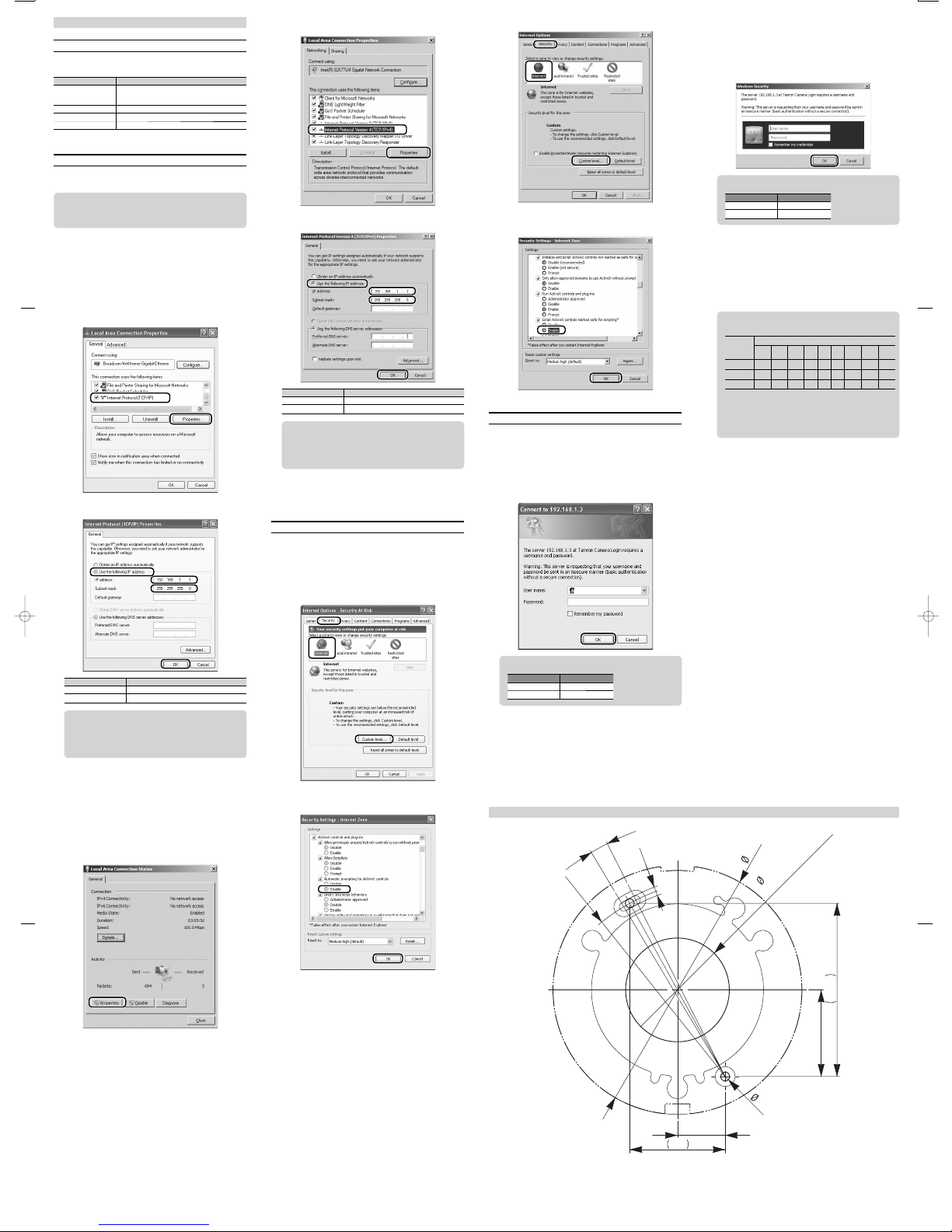
1. Drill holes for the mounting screws
1Tape the template onto the installation location and drill 2 holes for the mounting
screws.
2Drill a hole for routing the cable.
3Remove the template.
2. Attach the anti-falling wire
1Attach the washer of the anti-falling wire to the camera with the wire fixing screw.
Anti-falling wire
2Attach the anti-falling wire to the installation location.
3. Connect the wiring cables
Put the connected cable in the hole for routing the cable.
LAN Cable
Power source cable
(positive (+), red)
Power source cable
(negative (-), black)
I/O cable (white/red IN/OUT1)
I/O cable (white/black IN/OUT2)
I/O cable (gray/black GND)
Audio output jack
Connection Cables
LAN Cable :
Connect to your network through the LAN cable adapter.
Power source cable : 12 VDC (positive)
(positive (+), red)
Power source cable : GND
(negative (-), black)
Audio output jack : Voice is output from the camera. Voice sent to the
camera through the LAN cable also can be output.
Amplifier function is unavailable.
Prepare a speaker
with an amplifier.
Lip sync is not supported.
I/O Cable : Connects to external equipment. IN/OUT is white/red
(I/O1), white/black (I/O2) and white/red and GND is
gray/black.
* When setting to Output
NPN open-corrector output (Max. DC12V, 50mA)
* In case of Input setting
Switch to “ON” by external power voltage input.
(Max. DC12V, Required drive current: more than 1mA)
* For the detailed setting of input/output, make/break settings,
Please set up by camera web-browser (EVENT).
●The cables are not water-proof. When installing outdoors or in a dusty envi-
ronment, provide water-resistance for the cables by using such materials as
putty, self-fusing tape, PF tubing or electrical conduit.
●The power source cable is not required when power is supplied to the camera
through the PoE (Power over Ethernet) hub.
●The state of the camera can be checked by the indicator panel at the side of
the camera after power is supplied to the camera.
●If you do not use cables such as power, I/O cables, please do insulating.
STS : Orange is shown immediately after power has been supplied
and green is shown when images can be output.
LINK : The network operating conditions are indicated by blinks.
INT switch : Returns to the factory-set state.
RST switch : Restarts the camera.
PN (PAL/NTSC) selection switch:
Sets analog video output to either PAL or NTSC mode.
* Set each switch with an object that has a sharp-pointed tip.
[Procedure to remove cap when connecting terminal]
1Loosen the cap screw completely.
2Remove the cap hooking its protrusion.
Note: Do not pull the cap screw violently. Joint of cap rubber may be broken.
Connecting LAN cable
Connect the usable LAN cable to a hub or your PC.
Connecting to hub : Use the straight cable.
Connecting to PC : Use the cross cable.
Usable LAN cable
•
STP (Shielded cable is recommended)
• Category 5e or higher
• Length in 100 m or less
LAN environment
• A 10BASE-T /100BASE-TX network mutually connected through an ap-
propriate device, such as a switching hub, conforming to IEEE802.3 is
recommended.
• Use an appropriate device, such as a switching hub, conforming to
IEEE802.3af if you utilize Power over Ethernet (PoE).
Recommended hub: Allied Telesis's FS917-PS
4. Mount the camera
Align the base of camera onto the mounting position and fix with 2 commercially
available screws.
5. Adjust and verify camera image
Connect to the camera from your PC through network and adjust and set the
camera and image.
→See "Owner's Manual - Operation" (PDF file).
■
■
■
Analog image output
When adjusting the angle of view at the installation, a camera image can be
displayed on a video monitor etc. by connecting the RCA mini plug and video
cable (RCA) to [VIDEO] of the indicator panel. The output to a video monitor
supports both of the NTSC and PAL signal systems.
RCA mini plug
Push the terminal cap completely and tighten the screw to maintain the
water-proof function after adjustment and check.
Caution
Failure to attach the terminal cap properly may result in a malfunction be-
cause the product will not maintain waterproof performance (IP66).
6. Place the cover
→See "Placing the Cover"
Extended from the Ceiling or a Wall
Attach to the mounting arm etc.
1. Connect to the wiring cables
→See "Mount the camera"
2. Attach the camera to the mounting arm using the installation
hardware supplied with it
Use a commercially available mounting arm.
3. Adjust and verify camera image
Connect to the camera from your PC through network and adjust and set the
camera and image.
→See "Owner's Manual - Operation" (PDF file).
4. Place the cover
→See "Placing the Cover"
Place the cover
Place the cover on the camera.
1Tighten the mounting screw until the screw head sits 3 to 4 mm above the side of
the camera.
Lens protective cover
Mounting screw
2Remove the lens protective cover.
3Hook the claw of the cover as shown in the illustration, attach the cover to the
camera, and tighten the screw.
Tab
Product Specifications
Model 300QV-P-CM
Lens specifications f=1.09mm
F/1.7
Horizontal angle of view 180°
Lens type Fish-eye lens
Image sensor 1/4" progressive CMOS
Image output Original image: QuadVGA (1280 x 960)
Corrected image: select from VGA (640 x 480) or QVGA
(320 x 240)
Simultaneous output
Effective pixels 2048 (H) x 1536 (V)
Pan Electronic pan
Tilt Electronic tilt
Zoom Electronic zoom (8x)
External dimensions Ø120mm
Image compression format H.264, MPEG-4, M-JPEG
Other functions Distortion correction
9 preset positions and preset sequences
Motion detection
Panorama display (2-stage)
Ceiling, side, desktop mode
Split display (up to 4-split screens)
Power supply PoE or DC12V
Power consumption 4.5W
Mass App. 470g
Dimensions
Cover is not placed Unit: mm