Tanaka 58611 User manual

®
• , ,L:;'" (_ .)¸:i_:_:::_:_i:i_' i_::_:";_X, ' :'::: ::?:":'_,:::" :.::_:":" :
m

YOUR NEW
POWERFUL OUTBOARD
//.
R
SAFETY,
MOTOR ! A
YOUR OWN
S :
TO' ...........BEFORE ATTEMPTING _
YOUR NEW iUNIT. FAILURE TO FOLLOW
INSTRUCTIONS CAN LEAD TO SERIOUS
PERSONAL INJURY.
Safety Alert Symbol and Notations
The following safety notations are used throughout
this manual to call attention to special information
or operating procedures.Understand the message
in each notation and be alert to unsafe conditions
and the possibility of personal injury.
NOTE: A NOTE points out general reference
informationregarding properoperationand mainte-
nance practices.
IMPORTANT: An IMPORTANT statement indicates
specific procedures or information that is required
to prevent damage to the machine or its attach-
ments.
,Tanaka Ltd, reservesthe rightto make changes or-
::_:_improvementsi:to:!ts products:at :afiy time :without: :
::i:!n:_urring::!:any::ob!igation-,to make suchchangest 0
products manufactured previously. Tanaka Ltd., or
its dea!e[s, accept no responsibility: for_variations
which may be evident in the actual specifications
of its products-and statements and descriptions
contained in this publication.
©Tanaka Ltd. 1990
i 1111111111111111111111111 iiii rl
This safety alert symbol Is used to at-
tract your attent!onl PERSONAL SAFE-
TY IS INVOLVED! When you see this
symbol -BECOME ALERT- HEED ITS
MESSAGE. .....
,_ CAUTION: A CAUTION Identifies safe
operating practices or Indicates unsafe
conditions that could result In personal
Injury.
WARNING: A WARNING describes a
condition where failure to follow the
lnstructlons could result in severe per-
sonal Injury.
,DANGER: A DANGER designates a
condltlon where failure to follow Instruc-
tions or heed warnlng will most likely
result In serious personal Injury or
death.
945606
Part No. 045607
Printed In U.S.A. 12/90

Owners Responsibility and Operating
Safety Checklist
This product is not intended for children and
should not be used at any time without adult
supervision.
IN CASE OF EMERGENCY, THE ENGINE
SHOULD BE SHUT OFF IMMED1ATELYI THE
ENGINE CAN BE STOPPED BY DEPRESSING
THE STOP BUTTON OR PLACING THE CHOKE
KNOB rN FULL CHOKE POSITION.
Before starting, make sure your motor is securely
.
mounted to the transom.
Do not fill:fuel tank with motor runningornear any
flame or lighted Smoking matedaK
Do not stand in a small boat. Do not swim around
b0at with mot0r running'
Besure to have piierS, screwdriver, wrench, spare
spai'k plugs, and cotterl pins in boat whenever
leaving shore.
Keep fire fighting and iifesaving equipment in good
condition and readily accessible at all times.
When loading boat distribute the load evenly; keep
the load low; don't stand in 8 small boat. Take
weather and water conditions into account.
Donor permit persons to ride on parts of the boat
not designed for such use. Keep an alert lookout.
Observe all ULSi Coast: Guard regulations.
Specifications
Cylinders/H.P ............... 1/.75 @6500
Bore/Stroke .......... 1.268 in. (32.21 ram)/
1.023 in. (26 ram)
Displacement ..................... 21.2 c.c.
Controls ..... Positive action throttle, kill switch
Steering .. 'D" type handle w/360 degree sweep
Ignition .............. Electronic, solid state
Carburetor ......... Non-palmer, all position,
diaphragm type
Cooling system ................. Air cooled
Transom height ................ 15" max.
Propeller ............ 3 blade, 2.0" diameter
Fuel capacity ................. 16:0 fl. oz.
Running time .............. 35:45 minutes
Actual weight (Dry) ..... .... ....... ,9.2 Ibs.
Fuel mixture .. 50 to 1 Ratio of regular gasoline
to Tanaka Perfect Mix 2 Cycle Oil
or equivalent BIA certified TC-W
2 Cycle Lubricant
RECOIL
CARBURETOR STARTER
KILL
SWITCH
THROTTLE
LEVER
l
HANDLE
DOWNTUBE
GAS
TANK
CLAMP
(Shown in reverse
TiLTPOsitionforclarity)
LOCK
i
i SKEG
k
PROPELLER

Fuel and Lubrication
Lower End r IMPORTANT: Failure to mix oil with gasoline will
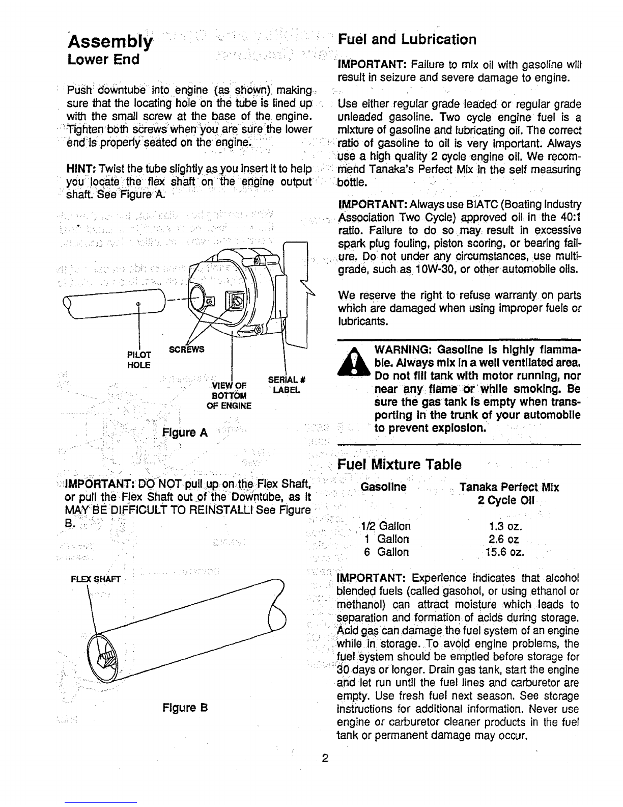
:Push id0wntube into engine (as shown)making •result in seizure and severe..,damage to engine.
sure that the locating hole on the tube is lined up Use either regular grade leaded or regular grade
wit_ the small screw at the base of the engine, unleaded gasoline. Two cycle engine fuel is a
;iTigiiten both screWsWhen you! are Surethe lower mixture of gasoline and lubricating oil. The correct
;endis;properlySedted on theengine_ _ii:, • ___i ratio-of gasoline to oil is very importanL Always
......''_: _ ..... _use ahigh quality 2cycleengine oil. We recom-
HINT: Twist the tube slightly asyou insertitto help _: mend Tanaka's Perfect Mix in the self measuring
: you Iocate;the_flex Shaft on';{he erjgine output: .;;.bottle. .:. " '....
Shaft,:SeeFigur;eA. _; : _;`_'_";:IMPORTANT: Always use BIATc (Boating Industry
........ , :_•_ , _i ,i:,i_,__:_;,,!
• _ .... j:• "_•:.! :;•_ _••'•;•i_ • ...... ii
PILOT
HOLE
VIEW OF
BOTTOM
OF ENGINE
Figure A
SERIAL #
LABEL
_ --._Association .Two Cycle) approved oil in the 40:1
ratio. Failure to do so-may result in excessive
spark plug fouling, piston scoring, or bearing fail-
....`_ .ure, Do not under any c=rcumstances, use multi-
. J 'grade, such.asl0W-30, or other automobile oils.
I _ We reserve the right to refuse warranty on parts
t l which are damaged when using improper fuels or
lubricants.
_WARNING: Gasollne is highly flarnma-
ble. Always mix In a well ventilated area,
Do not fill tank with motor running, nor
near any flame or while smoking. Be
sure the gas tank Is empty when trans-
porting in the trunk of your automobile
to prevent explosion.
Fuel Mixture Table
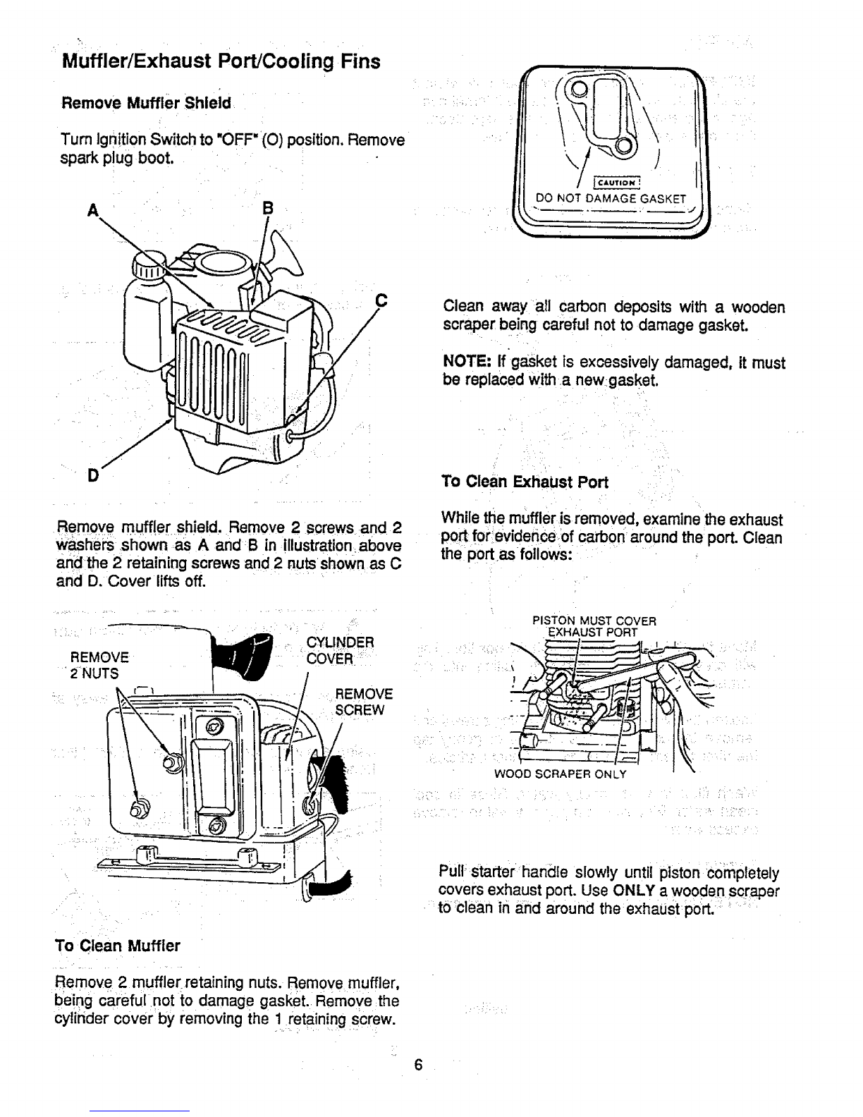
IMPORTANT: Do-NOT puli,uP ontheFlex Shaft, "
or pu!l theFlex Shaft out 0f_iheDowntube, as it
M/_Y;BE DIFFICULT TO REINSTALLI See Figure
B;
Gasoline Tanaka Perfect Mlx
2 Cycle 011
1/2 Gallon 1.3 oz.
1 Gallon 2.6 oz
6 Gallon 15.6 oz.
FLEXSHAFT
Figure B
:;_ IMPORTANT: Experience indicates that alcohol
blended fuels (called gasohol, or using ethanol or
methanol) can attract moisture .which leads to
separation and formation of acids during storage.
Acid gascan damage the fuel system of an engine
iwhile in storage. To avoid engine problems, the
fuel system should be emptied before storage for
30 days or longer. Drain gas tank, start the engine
and let run until the fuel lines and carburetor are
empty. Use fresh fuel next season. See storage
instructionsfor additional information. Never use
engine or carburetor cleaner products in the fuel
tank or permanent damage may occur.
2

OPERATING INSTRUCTIONS .Move Choke Lever to RUN positio n.
Pull starter rope again. Engine should start within
Boat Mounting ,:i: two to four pulls: If engine fails to start repeat all
'•:, ...... _previous steps. _ • ,,.
Mount the motor in the center of boats transom,_ :; -:: ,-:, . ..... ' ...... _:
trear) ; , " _,
Hand Tighten the clamp bracket clamp, Do not use
;, awrench or any other device thatwould cause
,damage to the clamp, ,;
Be sure the Tilt Lock is properly fastened and in
the correct, position for locking inreverse.
i •
......... DANGER: Keep hands and feet away _
from the lower end of the Bumble Bee
AT ALL TIMESI
Warm Engines,,:, :<- ,-_,:_
Sameas cold engine except choke: lever must be
in_RUN position. _ ; '"" '_
.... ,
IMPORTANT: Always pull Starter R0pe.straight
' out: Pulling startei" a:t an_angtewi[I _causerope to
rub against the eyelet. This friction will cause the
rope to fray and wear more quickly.
Although the engtnels air,cooled,• it Is
possible to burn your hands on the
engine block and upper portion of the
column DO NOT TOUCHI
STARTING INSTRUCTIONS
Cold Engine
STOPPING INSTRUCTIONS
.Press •,KILL SWITCH, at rear of Handle. (See
Figure C) -;
• .
Incase of emergency, the enginecan be stopped
by placing the, choke in the Full Choke Position.
KILL
SWITCH
Make sure the outboard motor bracket is securely •
fastened to transom ofboat.
Move choke Lever to START position.
Hold throttle lever in full open position.
Pull starter rope out until resistance is felt. (Ap-
proximately 2 in.)
Pull starter rope with a series of smooth rapid pulls
until engine starts or attempts to start.
THROTrLE
\\
Figure C
3

Removing Motor From Boat
Always tilt motor by liftingon rear.of shroud. DO
:NOT PUSH DOWN ON THE STEERING HANDLE.
When removing the motorfrom the boat, raise the
outboard in upward direction until the propeller
clears the transom.
Salt Water Operation =
Spray exposed metal surfaces with
equivalent. WD-40 or
Never leave the lower unit in salt water overnight.
Wipe exterior completely with fresh water cloth and
then apply light coating of oil.
Lubricate propeller shaft occasionally with a water-
proof type of lubricant (Lithium Grease), thus
enabling the propeller to be removed easily.
. To materially increase the.life of all exposed parts ...........
and decorative finishes, follow thesteps indicated " : '
below: :: •.... '" It is good practice when operating in salt water to
inspect your motor daily and to apply a light coat-
Always tilt your motor out of the water when not in ........ing.of grease to any part or area that shows
' _": evidence:of:corrosion or rust, :" . .:r_
Maintenance lnstructions ,-
PreventiveMaintenance ....._ _.. ,:,, , _u, .
....... ..... : _..... : ' ......... '_ CHECKLIST
Service, other than the items listed here in your
Users Manual maintenanceinstructions, should be
performed by your authorized Servicing/Dealer.
Keep unit clean. Do not allow filters, muffler, and
cy!inder :fins,to ..become plugged or covered with
dust, : dirt or other foreign material, _:NEVER .use
dirty fuel or oil. Enginedamage could result.
A good preventive maintenance program will
prolong the life and maintain the performance of:
your Tanaka unit. ,!
Preventive Maintenance Chart
NOTE: Themaintenance. check chartis a guide for
Preventive Maintenance; •[Cleaning,: a_ustment,
_and parts replacement may, under certain condi-
tions, be required at more frequent intervals than
those indicated. ::
ii,"",i, ,i,,,,,
Item Maintenance
Scr_srNuts/Bo_s
Controls
_LF,Jter _•
Muffler
_pectrnghten
Inspect
*Replace As
Required
Clean or .
Replace
Clean
Spark Plug
ExhaustPorts
StarterRope
Carburetor
Fuel Filler-
FeU:ITank :
Clean!Adjust/
:Replace
C
H
*Clean
U
S
E
.I _o 2o
.... H H
O O O
U U U
R R R
S S S
H
Clean .... : , ' •
Inspect
l'Reptace " _.... '" J
.... i
"Replace
.... Ciean ......
(Flush with : '
Clean Fuel)
Fuel Hose Check
*Replace as
Required
Lamination Gap "Clean!
•Adjust
"Recommended for Maintenance by an Authorized Dealer.

Air Filter
IMPORTANT: NEVER operate your unit without
the air filter. Dust and dirt will cause internal dam-
age to the engine. The filter must be kept clean. If
it becomes damaged, !nstall a new filter.
To Clean Air Filter:
Remove dirt from around the air filter cover to
prevent dirt from falling int0the air box.
\
Disconnect black rubber boot from spark plug with
atwist and pul[m0tion. . ' .i
....Using a spark p!ugwrench,-remove spark plug. Do
,.not use any other type wrench,
-:_i _'_.Use a"wire brush to clean spark plug!:ilClean
_'_electrodes with emery Cloth. Do not use a grittype
cleaning machine: "" .......
Move the CHOKE lever tO.the choke position. This
will prevent dirt from aCcidently falling into the
carburetor. :':' .....
Loosen the two air filter cover retaining screws and
remove thecover and filter. Shake or gently tap
the filter to remove loose dirt and dust l_articles.
Wash-filter in warm soapy water. Rinse in cool
clean water. Blot filter with paper towel to remove
excess water.
Reinstall air filter in reverse order of removal. _
:':_NOTE!Rep!ace filter if frayed, tom ord_aged.
Spark Plug
Move Ignition Switch to "OFF" (O) position.
ii i==1 i i
WARNING: Wear eye protection during
this procedure
Use Compressed air to blow all dust away after
Spark_plug has been cleaned.
Usinga gaping tool, adjust gap to ,025" (.5ram).
Bendbnly the side electrode,
T GAP
:i
_Reinsta!l spark plug, Install plug by hand andthen
using a:spark plug 'wrench tighten to 1i0 inch
•._'pounds torque. " ...........
5

MufflerlExhaust Port/Cooling Fins
Remove Muffler Shleid
Turn IgnitionSwitch to "OFF"(O) position,Remove
spark p!ug boot.
H
•B
C
i ¸ _
DO NOT DAMAGE GASKET
N,,=_ ,, ,
Clean away all carbon deposits with awooden
scraper being careful not to damage gasket.
NOTE: If gasket is excessively damaged, it must
be replaced witha newgasket.
D
Remove muffler shield. Remove 2 screws and 2
Washers shown as A and B in illustration above
andthe 2 retaining screws and 2 nutsshown as C
and D. Cover lifts off.
REMOVE
2 NUTS
CYLINDER
=cOVER _
REMOVE
SCREW
To Clean Muffler
Remove 2 muffler retaining nuts. Remove muffler,
being careful not to damage gasket. Remove the
cylinder cover by removing the ! retaining screw.
To Clean Exhaust Port
While the muffler is removed, examine the exhaust
port for evidence of carbon around the port. Clean
the port as follows:
PISTON MUST COVER
EXHAUST PORT
WOOD SCRAPER ONLY
Pull_starter handle slowly until piston completely
covers exhaust port. Use ONLY awooden scraper
tOclean in and around the exhaust port.

To Clean Cooling Fins
COOLING FINS /
WOODEN SCRAPER
..........Use wooden scrapper to clean away debris from
cylinder cooling fins.
Carefully turn Low and High speed needles gently
clockwise until resistance is _felt. Do not turn
needles in too tight or you can damage needle tips
and:their seats:Then open each needle turning
counterclockwise one (1) fut! turn. '
,Start engine and let it warm up at low speed. If
engine will not idle without stopping, turn Id!e
screw slowly clockwise untilengine idles.
•••i ii:•i ii i;i
iOLE
\! SCREW
Reinstall cylinder cover and retaining, screw.
Reinstall muffler. Reinstall muffler retaining nuts.
Tighten securely. Reinstall Muffler Shield in re-
verse order of removal.
Carbu retor Adjustment
Carburetor adjustment is cdticat and ifdone care-
lessly candamage carburetor and engine.
Before making any adjustments make sure air filter
is clean. Very often a dirty air filter will make the
engine operate as though a carburetor adjustment
is needed.
To adjust Carburetor:
TURN NEEDLES OUT
TURN NEEDLES IN
LH
Accelerate engine several times, adjust low speed
needle to obtain smooth, rapid accelerationwithout
hesitation or falter, if needle isincorrectlyadjusted,
engine wilt hesitate or falter when accelerated.
Adjust High speed needle for best power under
load; finalposition of high speed needle will usually
be about one (1) turn open.
IMPORTANT: Improper adjustment of high speed
needle may cause a lean running condition which
can result in engine damage.
Check idle engine operation again. It may be
necessary to readjust idler speed screw slightly for
smooth Idle and acceleration.
IMPORTANT: Engine performance is determined
by the poWerandease ofoperation under load. Do
not adjust carburetor for maximum sound level as
this is likely to result in alean condition which will
cause engine damage.
If uncertain about proper carburetor adjustment,
take unit to your nearest Authorized Servicing
Dealer for service.
7

Storing A Unit
When,storing unit for a month or at end of season,
the following maintenance is required: .... _,
Maintenance Log Chart
Date Maintenance Performed
Start engine. Run engine at idle speed until,unit
:warms up.
Turn engine "OFF'. Drain fuel from fuel tank.
After fuel is drained, start engine. Run engine at
idle until unit stops. This will purge the carburetor
of fuel.
Clean exterior of engine and lower end.
Remove spark plug.
.... ! _i ¸
i,Hi H,il H HL '' I
Pour one (1) teaspoon of clean oil into the corn- _.
bustion chamber. Pull starter rope slowly several
times to coat internal components. Replace spark
plug. i
:. Perform allthe general maintenance recommended
inthe Maintenance instruction section of your User
Manual.
Store unit i.n acool dry place away from any
source of Ignition such as an oil burner, gas, hot
water heater or gas dryer, etc.
Removing A Unit From Storage
To Remove. Unit From Storage:
Remove spark plug.
Pull starter rope briskly to clear excessoil from
combustion chamber.
Clean and gap spark plug or install a new spark
plug with proper gap.
Prepare unit for operation.
Fill fuel tank with proper fuel/oil mixture. See Fuel
and Lubrication Section.

Troubleshooting Checklist
Engine ,Starts
DoesNot ButDoes
Start NolRun
× ×
Does DoesNot
Engine Not Develop 'SeeYourServiceDealer
Misses Idle FullPower
Fue!Tank Emotv
....X. X
X
.....X......X,
X .......... X
x X
xX
._ X .........X
...................X X FuelLineKinkedorPinched
X X FuelFilterOir_orClooQed
XX VentScrewonFue TankFiter CaDClosed
XQ_trburetorPassaoosCl_oedorDirty
X IncorrectFuel_gMixture ....
XX
X, ,,, XXX X
I x x × 'x x
X
X.
X X X X............
X X
X........ X .......
..............X X
CarburetorCuto(Adiustment
EnoineFlooded
WronOTvoeS_rk Pluo
DefectiveorFouledSp_ P!_
DefectiveMaqn_to
SoarkDoesNotJumpS_rkPIuoGap t
X _ EnoineO,,.,tofTime
X ..Weakbnit_onColl
........SparkPluoLeadWireNOtSecured
FrayedorCrockedLead'_re nsualion
Di_nnected.Groundedor LooseWirinonElectdcaSystem *.....
ProDeilerBoundby_reiQnO_ects(Rshin¢_Line.We_s, Etc.1
Hi_ TensionLead- SaltWaterBuildUD
IMPORTANT INFORMATION
MODEL: 58611
SERIAL NUMBER
DATE OF PURCHASE
INSURE YOUR ENGINE
Many insurance companies offer protectioncontractsfor
your boat and outboard engine. Insurance covering your
own equipment against damage, theft, etc., as well as
liability insurance for property damage and personal
injury to others is available. It would be Wise to contact
your insurance agent for further information about
adequate protection.
Place SedaJNo, Label from Product
Registration Form Here.
Date No. Hrs,Used
OPERATING LOG
Gais. Fue! Used Date ..N0.H.rs. Use,d
,_,. •
,i,i
Gals,_,,,,,,,FuelUsed
.,,,,,,,.
This manual suits for next models
2
Table of contents
Other Tanaka Outboard Motor manuals
Popular Outboard Motor manuals by other brands

Torqeedo
Torqeedo Cruise 12.0 R TorqLink Translation of the original operating instructions

TOHATSU
TOHATSU M 40C owner's manual

Vetus
Vetus BOW PRO A Series installation instructions

Mercury
Mercury 250 XS OptiMax Operation, maintenance & installation manual

Sleipner
Sleipner ERV130 installation guide

Torqeedo
Torqeedo DEEP BLUE 80 operating instructions