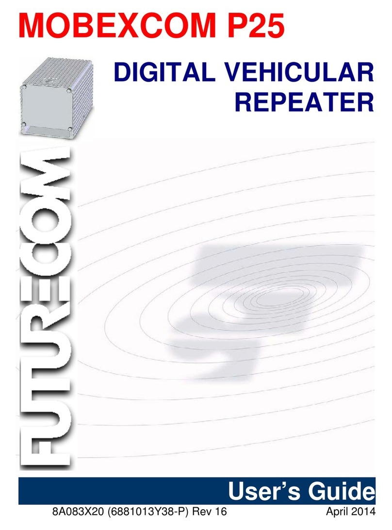
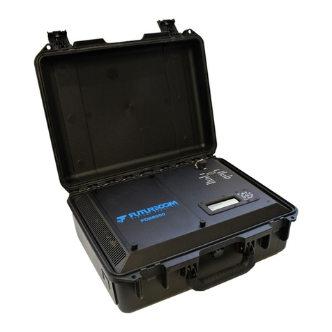
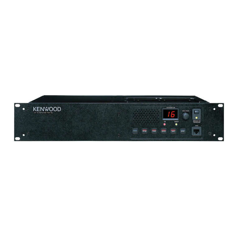
Futurecom PDR8000 User manual

Futurecom Systems Group, ULC
PDR8000®Portable Digital Repeater
Product Planner
Document: 8K088X02
Revision: R5.0
Date: 2021-11-15

Document 8K088X02 R5.0
PDR8000® Portable Digital Repeater Product Planner
2021-11-15 Page 2 of 64
Subscribe to our newsletter if you want to be informed about new releases and updates.
Please visit http://futurecom.com/support/newsletter/
Proprietary Statement
©2021 Futurecom Systems Group, ULC
All Rights Reserved
Futurecom®, DVR-LX®, PDR8000®, the Futurecom Logo and the Stylized FC logo are
registered trademarks of Futurecom Systems Group, ULC. All other trademarks are the property
of their respective owner.
No part of this document, or any software included with it, may be reproduced and distributed
without the prior written permission of the copyright holder.
Futurecom Systems Group, ULC reserves the right to make changes or improvements to the
equipment, software or specification described in this document at any time and without prior
notice. These changes will be incorporated in the new releases of this document.
This document may contain technical inaccuracies or typographical errors.
Futurecom Systems Group, ULC waives responsibility for any labour, materials or costs
incurred by any party as a result of using this document.
MOTOROLA, MOTO, MOTOROLA SOLUTIONS and the Stylized M Logo are trademarks or
registered trademarks of Motorola Trademark Holdings, LLC and are used under license. All
other trademarks are the property of their respective owners.
Note: PDR8000 is sold exclusively by
Motorola Solutions, Inc. worldwide

Document 8K088X02 R5.0
PDR8000® Portable Digital Repeater Product Planner
2021-11-15 Page 3 of 64
Table of Contents
1Introduction.............................................................................................................9
1.1 Key Features & Benefits ....................................................................................9
1.2 Applications......................................................................................................10
2PDR8000 Hardware form factors........................................................................11
2.1 PDR8000 Suitcase...........................................................................................11
2.1.1 Internal Duplexer .................................................................................................12
2.1.2 Simplex................................................................................................................12
2.1.3 Simplex with Booster Pack...................................................................................13
2.1.4 Internal Duplexer and Booster Pack.....................................................................13
2.1.5 External Duplexer................................................................................................13
2.1.6 External Duplexer and Booster Pack ...................................................................14
2.1.7 Booster Pack .......................................................................................................14
2.2 Rackmount PDR8000 ......................................................................................15
2.2.1 Internal Duplexer .................................................................................................17
2.2.2 Internal Duplexer and 50W Power Amplifier.........................................................17
2.2.3 External Duplexer................................................................................................17
2.2.4 External Duplexer and 50W Power Amplifier .......................................................17
3PDR8000 Use Cases.............................................................................................18
3.1 Wireline Repeater and Base Station................................................................18
3.1.1 V.24 Wireline Repeater........................................................................................18
3.1.2 Ethernet Wireline Repeater..................................................................................19
3.2 Back to Back Cross Band Repeater (RT/RT)...................................................20
3.3 Standalone Repeater.......................................................................................20
3.4 Wireline Satellite Receiver/Transmitter............................................................21
4Deployment Profiles.............................................................................................22
5Supported Functional Configurations ................................................................23
5.1 Platform Configurations....................................................................................23
5.1.1 PDR (Portable Digital Repeater)..........................................................................23
5.1.2 Satellite Receiver.................................................................................................23
5.1.3 Satellite Transmitter.............................................................................................24
5.2 RF Configurations (Base or Repeater).............................................................24
5.2.1 Repeater..............................................................................................................25
5.2.2 Base Station ........................................................................................................26
5.3 Channel Configurations (Full/Half Duplex).......................................................26
5.3.1 Full-Duplex ..........................................................................................................26
5.3.2 Half-Duplex (& Simplex).......................................................................................27
5.4 Illustrative Examples........................................................................................28
5.4.1 Base Station –Half-Duplex channel.....................................................................28
5.4.2 Base Station –Full-Duplex channel.....................................................................28
5.4.3 Repeater with Infrastructure.................................................................................29
5.4.4 Standalone Repeater...........................................................................................29
Document 8K088X02 R5.0
PDR8000® Portable Digital Repeater Product Planner
2021-11-15 Page 4 of 64
6Product Capabilities.............................................................................................30
6.1 Radio System Support .....................................................................................30
6.2 Multiple-Channels ............................................................................................30
6.2.1 Transmit Frequency.............................................................................................30
6.2.2 Receive Frequency..............................................................................................30
6.2.3 Transmit Power Level..........................................................................................31
6.2.4 Wireline Time-out Time........................................................................................31
6.2.5 Repeater Time-out Time......................................................................................31
6.2.6 Repeater Drop-out Delay.....................................................................................31
6.2.7 PTT Priority..........................................................................................................31
6.2.8 BSI (Base Station Identication) ............................................................................32
6.2.9 Monitor Before Data Transmit..............................................................................32
6.3 RF Frequency Bands.......................................................................................32
6.4 Wireline Interfaces ...........................................................................................33
6.4.1 V.24 Wireline Interface.........................................................................................33
6.4.1.1 Site/Subsite Number, TEI (Terminal Endpoint Identifier)...............................33
6.4.1.2 V.24 Transmit Clock Synchronization ...........................................................34
6.4.2 Ethernet Wireline Interface...................................................................................34
6.4.2.1 DFSI Features ..............................................................................................35
6.5 Fallback In-Cabinet Repeat..............................................................................35
6.6 Squelch and Channel Access ..........................................................................36
6.6.1 Analog Signal Squelch & Access Operation.........................................................36
6.6.1.1 Multi-Coded Squelch (PL/DPL).....................................................................37
6.6.1.2 Multi-Coded Squelch: Normal (Multi-PL/DPL not enabled)............................38
6.6.1.3 Multi-Coded Squelch: Multi-PL/DPL..............................................................38
6.6.2 Digital Signal Squelch & Access Operation..........................................................39
6.6.2.1 Network Access Code (NAC)........................................................................39
6.6.2.1.1 Rx NAC Operation: Normal........................................................................40
6.6.2.1.2 Rx NAC Operation: Receiver Monitor ........................................................41
6.6.2.1.3 Rx NAC Operation: Community Repeater..................................................41
6.6.2.1.4 Rx NAC Operation: Multi NAC...................................................................41
6.7 Data Services...................................................................................................42
6.8 Adaptive Power Control ...................................................................................42
6.9 Service/Configuration Software (Futurecom Repeater Configurator (FRC)) ....43
6.10 Status Indication LEDs.....................................................................................43
6.10.1 Front Panel Indicators..........................................................................................44
6.10.2 Side Panel Indicator (PDR8000 Suitcase Only) ...................................................45
6.11 Local (Front Panel) Control..............................................................................45
6.11.1 Local PTT Tests...................................................................................................46
6.11.2 Keypad/Display....................................................................................................46
6.12 Input Power options and indications.................................................................47

Document 8K088X02 R5.0
PDR8000® Portable Digital Repeater Product Planner
2021-11-15 Page 5 of 64
6.12.1 Optional External Battery Pack ............................................................................47
6.13 Suitcase/Housing.............................................................................................48
6.14 External Ports - PDR8000 Suitcase.................................................................49
6.15 External Ports - Booster Pack..........................................................................51
6.16 Open/Closed Case Operation (Suitcase Only).................................................52
6.17 Zippered Accessory Pouch ..............................................................................52
6.18 RT/RT Configuration (V.24 interface only) .......................................................53
6.19 Antenna Switch................................................................................................53
6.20 ASTRO Fade Tolerance...................................................................................54
6.21 Conventional Talkgroup Operation...................................................................54
6.22 Purchasable Software Options.........................................................................55
6.23 Configuration Safeguarding..............................................................................55
7PDR8000 Specification.........................................................................................57
7.1 PDR8000 Suitcase Specification summary......................................................57
7.2 Booster Pack Specification Summary..............................................................59
7.3 Rackmount PDR8000 Specification Summary.................................................60
7.4 External Battery Pack Specification Summary.................................................62
8Appendix A: Revision History .............................................................................64

Document 8K088X02 R5.0
PDR8000® Portable Digital Repeater Product Planner
2021-11-15 Page 6 of 64
List of Figures
Figure 1: PDR8000 Suitcase...................................................................................................... 9
Figure 2: Rackmount PDR8000 ................................................................................................. 9
Figure 3: Internal Duplexer Cavity.............................................................................................11
Figure 4: Internal Duplexer Hardware Topology........................................................................12
Figure 5: Simplex Hardware Topology......................................................................................12
Figure 6: Simplex with Booster Pack Hardware Topology.........................................................13
Figure 7: Internal Duplexer and Booster Pack Hardware Topology...........................................13
Figure 8: External Duplexer Hardware Topology.......................................................................13
Figure 9: External Duplexer and Booster Pack Hardware Topology..........................................14
Figure 10: Booster Pack............................................................................................................14
Figure 11: Rackmount PDR8000 Front Panel ...........................................................................15
Figure 12: Rackmount PDR8000 Back Panel............................................................................16
Figure 13: Internal Duplexer Hardware Topology......................................................................17
Figure 14: Internal duplexer with 50W Power Amplifier Hardware Topology .............................17
Figure 15: External Duplexer Hardware Topology.....................................................................17
Figure 16: External duplexer with 50W Power Amplifier Hardware Topology............................17
Figure 17: V.24 Wireline Repeater and Base Station Use Case................................................19
Figure 18: Ethernet Wireline Repeater and Base Station Use Case..........................................19
Figure 19: RT/RT Use Case......................................................................................................20
Figure 20: Standalone Repeater Use Case...............................................................................21
Figure 21: Half-Duplex Base Station Example ..........................................................................28
Figure 22: Full-Duplex Base Station Example...........................................................................28
Figure 23: Repeater with Infrastructure Example ......................................................................29
Figure 24: Standalone Repeater Example.................................................................................29
Figure 25: Front Panel LEDs and Switches...............................................................................44
Figure 26: Front Panel Keypad/Display.....................................................................................46
Figure 27: Optional External Battery Pack.................................................................................47
Figure 28: PDR8000 Closed Case............................................................................................48
Figure 29: Booster Pack Closed Case ......................................................................................49
Figure 30: PDR8000 External Ports..........................................................................................50
Figure 31: Booster Pack External Ports ....................................................................................51
Figure 32: Zippered Accessory Pouch ......................................................................................53
List of Tables
Table 1: Duplexer Specifications for PDR8000 Suitcase...........................................................12
Table 2: Duplexer Specifications for Rackmount PDR8000.......................................................16
Table 3 - PDR8000 RF Configuration........................................................................................25
Table 4: Analog Access Code Table.........................................................................................37
Table 5: Digital Access Code Table ..........................................................................................40
Table 6: PDR8000 External Ports .............................................................................................51
Table 7: Booster Pack External Ports........................................................................................52

Document 8K088X02 R5.0
PDR8000® Portable Digital Repeater Product Planner
2021-11-15 Page 7 of 64
Glossary
TERM
DEFINITION
ASTRO®
P25-compliant digital communication system offered by Motorola
Solutions
BER
Bit Error Rate; identifies the quality degradation of a data stream over a
communication channel. Typically altered due to noise, interference,
distortion, or bit synchronization errors.
BSI
Base Station Identifier / Call Sign; sent over-the-air, sometimes as
Morse Code, to identify the originating transmitter
CAI
Common Air Interface (P25 standards-based RF Signalling)
CCGW
Conventional Channel Gateway (Conventional Channel Interface to
ASTRO 7.x system)
CTCSS
Continuous Tone-Coded Squelch System (In band signaling controlling
squelch control in analog radio systems), also known as Motorola PL
DCS
Digital Coded Squelch (In band signaling controlling squelch control in
analog radio systems), also known as Motorola DPL
DFSI
Digital Fixed Station Interface –Radio over IP interface protocol as
defined in TIA-102.BAHA-A standard document.
DIU / DIU3000
Digital Interface Unit; Provides wireline vocoding and encryption in
ASTRO 3.1 systems
DST
Daylight Saving Time
Duplexer
An electronic device that allows bi-directional (duplex) communication
over a single path. It isolates the receiver from the transmitter while
permitting them to share a common antenna.
Full-Duplex
Bidirectional simultaneous communications
FBICR
Fallback In-Cabinet Repeat: A mode of operation when PDR8000
activates a local-repeat function if it’s wireline link becomes impaired
FRC
Futurecom Repeater Configurator: The application for configuring
PDR8000 (formerly known as Tweaker)
GPS
Global Positioning System
GTR 8000
A model of Motorola Solutions base/repeater stations
Half-Duplex
Bidirectional communications utilizing two paths/frequencies, but only
one at a time
LED
Light Emitting Diode
Mixed-mode
channel
A radio channel carrying both P25 (CAI) and Analog FM radio traffic.
(Usually provided to help support legacy, non-P25 subscriber units that
need to operate at an incident scene where P25 subscriber units are in
use.)
NAC
Network Access Code; identifier driving squelch operation on received
Digital channels. Replaces PL/DPL (CTCSS/DCS) functionality from
analog radio systems.
OTAR
Over The Air Rekeying (method of updating encryption keys in devices
via encrypted over-the-air transport)

Document 8K088X02 R5.0
PDR8000® Portable Digital Repeater Product Planner
2021-11-15 Page 8 of 64
TERM
DEFINITION
P25
Project 25; a suite of standards for digital radio communications for use
by federal, state/province and local public safety agencies, enabling
communication within and between agencies during emergencies.
PDR
Portable Digital Repeater
PL/DPL
Private Line / Digital Private Line (In band signaling controlling squelch
control in analog radio systems); also known as CTCSS (Continuous
Tone-Coded Squelch System) or DCS (Digital Coded Squelch).
PTT
Push-To-Talk
QUANTAR
A model of Motorola Solutions base/repeater stations
RF
Radio Frequency; carrier and information sent via Electromagnetic
energy, “over-the-air”
RSSI
relative Received Signal Strength Indication
Rx
Receive
Simplex
Communications on a single path/frequency, allowing only one
transmitter at a time
Supplementary Data
services
“Lightweight” data services that supplement voice communications, e.g.
Talker ID, Status Update, Emergency indication, etc.
TEI
Terminal Endpoint Identifier (used in Message addressing on a wireline
interface)
Tx
Transmit
V.24
A digital link better described as a physical V.24 link with HDLC (High-
level Data Link Control). Used to connect PDR8000 to other
infrastructure elements (e.g. CCGW, DIU, comparator)
Voting / Comparator
Communication system elements that observe multiple received
signals, and choose the best (highest quality) to present to receiving
users.

Document 8K088X02 R5.0
PDR8000® Portable Digital Repeater Product Planner
2021-11-15 Page 9 of 64
1 INTRODUCTION
Special ops and security detail teams requiring enhanced,
Conventional, two-way radio network coverage can look to the
PDR8000 Portable Digital Repeater as their solution of choice
when on the move. Designed by Futurecom Systems Group in
collaboration with Motorola Solutions with these special teams
in mind, the lightweight suitcase is suited for discreet travel
whereas the Rackmount form factor is designed to fit in a
standard 19” rack
Set up the PDR8000 suitcase at a special event or incident
to swiftly provide local P25 or analog FM, on-scene
portable radio coverage. Connect to your dispatch console
wherever it may be via a V.24 (for P25) or Ethernet IP (Analog or P25) connection.
The platform the PDR8000 is based on, has been in the field
since 2006. Known generically as the DVR (Digital Vehicular
Repeater), this platform has an installed base of 30,000+ units
serving public safety first responders worldwide. For the
PDR8000, the DVR’s transceiver has been optimized to
minimize its weight and size, taking advantage of high
efficiency fans not available in the vehicle repeater application.
Futurecom’s PDR8000 transceiver platform benefits
from over a decade of harsh field service and proven
success.
1.1 KEY FEATURES &BENEFITS
•All Bands –VHF, UHF, 700 MHz* and 800 MHz
•Lightweight construction - less than 28 lbs. (including duplexer)
•Rapid deployment with AC* or DC power source capability
•Closed case operation at 50% Transmit duty cycle
•Easy to swap internal duplexer
•Able to use external duplexer
•End-to-end Encryption supported
•Voting and Comparator operation
•Standard output power of up to 20 watts (configurable) into duplexer
•Optional Booster Pack provides 50 watts output
•Platform support for future interfaces including Bluetooth and Wi-Fi
•Wireline V.24 serial connection to Motorola Solutions P25 system infrastructure
•Wireline Ethernet IP connection to consoles supporting Digital Fixed Station
Interface Protocol Version 1 (analog and digital)
•Standalone repeater for P25, analog FM, and mixed-mode operation
Figure 1: PDR8000 Suitcase
Figure 2: Rackmount PDR8000

Document 8K088X02 R5.0
PDR8000® Portable Digital Repeater Product Planner
2021-11-15 Page 10 of 64
•LCD screen & keypad allow easy access to Channel Change and other features
* Only available in Suitcase model
1.2 APPLICATIONS
•Special events
•Interoperability
•Dignitary protection
•In-building coverage
•Natural disaster
•Incident Scene response
•Discreet reconnaissance

Document 8K088X02 R5.0
PDR8000® Portable Digital Repeater Product Planner
2021-11-15 Page 11 of 64
2 PDR8000 HARDWARE FORM FACTORS
2.1 PDR8000 SUITCASE
PDR8000 suitcase form factor is typically a self-contained device but is easily modified to utilize
an alternate duplexer and/or a transmit power Booster Pack when required. Different RF
hardware combinations are supported, using accessible internal and external connection points
to enable the desired configuration. Note that the PDR8000 internal duplexer is easily
accessible and swappable. The cavity housing the internal duplexer is easily accessed by
removing a panel of the PDR8000 faceplate via four thumbscrews.
Figure 3: Internal Duplexer Cavity
The need to field-swap a duplexer depends upon the range of RF frequencies being used on
the different channels configured in a PDR8000. Duplexers have a defined Bandpass, meaning
that if widely diverse RF frequencies are used within the same RF band, it may be necessary to
install a different duplexer into the PDR when traversing frequencies (changing channels) to
another portion of the RF band. Duplexers typically cover a broad band of frequencies, but if
the frequencies on different channels are outside of the tuning parameters of the duplexer, it is
necessary to substitute a different duplexer when the channel is changed.
Several different duplexers are available, in different RF bands, and factory-tuned to customer
specified frequencies. Those available for purchase with the PDR8000 are listed below.
Customer supplied duplexers (installed inside the duplexer cavity, or outside of the PDR8000
case may also be used).

Document 8K088X02 R5.0
PDR8000® Portable Digital Repeater Product Planner
2021-11-15 Page 12 of 64
RF Band/Frequencies
Tx to Rx Separation
Bandpass Width
VHF
5 MHz
500 KHz
UHF 380 –430 MHz
10 MHz
100 KHz
UHF 380 –430 MHz
5 MHz
500 KHz
UHF 450 –470 MHz
5 MHz
500 KHz
700 MHz
30 MHz
6 MHz
800 MHz
45 MHz
10 MHz
Table 1: Duplexer Specifications for PDR8000 Suitcase
Note that the following diagrams illustrate the adaptability of PDR8000 suitcase by use of its
internal and external connection points. These diagrams do not represent a detailed view of the
circuitry within each of the elements.
2.1.1 INTERNAL DUPLEXER
Figure 4: Internal Duplexer Hardware Topology
2.1.2 SIMPLEX
Figure 5: Simplex Hardware Topology

Document 8K088X02 R5.0
PDR8000® Portable Digital Repeater Product Planner
2021-11-15 Page 13 of 64
2.1.3 SIMPLEX WITH BOOSTER PACK
Figure 6: Simplex with Booster Pack Hardware Topology
2.1.4 INTERNAL DUPLEXER AND BOOSTER PACK
Figure 7: Internal Duplexer and Booster Pack Hardware Topology
2.1.5 EXTERNAL DUPLEXER
Figure 8: External Duplexer Hardware Topology
External Duplexer cabling supplied by user.

Document 8K088X02 R5.0
PDR8000® Portable Digital Repeater Product Planner
2021-11-15 Page 14 of 64
2.1.6 EXTERNAL DUPLEXER AND BOOSTER PACK
Figure 9: External Duplexer and Booster Pack Hardware Topology
External Duplexer cabling supplied by user.
2.1.7 BOOSTER PACK
PDR8000 natively provides a pre-duplexer output power configurable up to 20 watts. If higher
output power is needed, configurations using an external Booster Pack can be utilized (see
2.1.3, 2.1.6). The Booster Pack configuration utilizes the standard PDR8000 suitcase
hardware/software and adds an additional suitcase (same dimensions/colors as the PDR8000)
which provides additional transmit power. The PDR8000 suitcase and Booster Pack are
connected via RF cables and a control cable. Output power of 50 watts (pre-duplexer) is
provided when using the Booster Pack.
Figure 10: Booster Pack

Document 8K088X02 R5.0
PDR8000® Portable Digital Repeater Product Planner
2021-11-15 Page 15 of 64
During operation of PDR8000 suitcase with a Booster Pack, the PDR8000 automatically detects
the presence of the Booster Pack and adjusts its output signal to be compatible with the Booster
Pack. The adjusted signal is then received by the Booster Pack which boosts the output signal
to 50W. (Note that the same PDR8000 can be used with or without a Booster Pack, allowing
the additional suitcase to be deployed only when needed.)
Addition of the Booster Pack to an existing (before Release 4) PDR8000 requires a firmware
update to the PDR8000 and its configuration software (Futurecom Repeater Configurator
(FRC).
Note that a Booster Pack can only be used with a PDR8000 built for the same RF band as the
Booster Pack. Different order codes are used to purchase Booster Packs for each of
PDR8000’s supported RF Bands. (Booster Packs are ordered for bands: VHF, UHF 380-430,
UHF 450-470, 700/800). A Booster Pack must not be connected to a PDR8000 built for a
different RF band.
For more detailed specifications of the Booster Pack, see section 7.2.
2.2 RACKMOUNT PDR8000
Some applications other than tactical use require added flexibility, which can be achieved with
the use of a Rackmount PDR8000 which is designed to fit into a standard 19” rack. Typical use
case for such applications are in-building coverage or remote areas having standard IT racks to
host Rackmount PDR8000.
The Rackmount PDR8000 gives you the flexibility of having the PDR8000 with options of
internal duplexers and/or 50 watts power amplifier, all packaged in a single 19” rack mountable
unit as shown on Figure 11 below.
The Rackmount PDR is powered by connecting it directly to a user supplied 12VDC Power
Supply.
Figure 11: Rackmount PDR8000 Front Panel

Document 8K088X02 R5.0
PDR8000® Portable Digital Repeater Product Planner
2021-11-15 Page 16 of 64
The Rackmount PDR8000’s front panel provides the same display keypad, LED panel and USB
connection as available on the suitcase form factor. In addition, the V.24 and the LAN
connections are also accessible on the front panel. The power supply, RF and optional alarm
connections are available at the back of the unit as shown in Figure 12.
Figure 12: Rackmount PDR8000 Back Panel
Rackmount PDR8000 offers several different duplexers, in different RF bands, and factory-
tuned to customer specified frequencies. These internal duplexers are secured in an enclosure.
Those available for purchase with the Rackmount PDR8000 are listed below.
RF Band/Frequencies
Tx to Rx Separation
Bandpass Width
VHF
5 MHz
500 KHz
UHF 380 –430 MHz
10 MHz
100 KHz
UHF 380 –430 MHz
5 MHz
500 KHz
UHF 450 –470 MHz
5 MHz
500 KHz
800 MHz
45 MHz
10 MHz
Table 2: Duplexer Specifications for Rackmount PDR8000
Customer supplied external duplexers open the possibility of utilizing other frequency separation
and bandpass width.
Note that the following diagrams illustrate the adaptability of Rackmount PDR8000 by use of its
internal and external connection points. These diagrams do not represent a detailed view of the
circuitry within each of the elements.

Document 8K088X02 R5.0
PDR8000® Portable Digital Repeater Product Planner
2021-11-15 Page 17 of 64
2.2.1 INTERNAL DUPLEXER
Figure 13: Internal Duplexer Hardware Topology
2.2.2 INTERNAL DUPLEXER AND 50W POWER AMPLIFIER
Figure 14: Internal duplexer with 50W Power Amplifier Hardware Topology
2.2.3 EXTERNAL DUPLEXER
Figure 15: External Duplexer Hardware Topology
2.2.4 EXTERNAL DUPLEXER AND 50W POWER AMPLIFIER
Figure 16: External duplexer with 50W Power Amplifier Hardware Topology

Document 8K088X02 R5.0
PDR8000® Portable Digital Repeater Product Planner
2021-11-15 Page 18 of 64
3 PDR8000 USE CASES
PDR8000 is a Base Station capable of Local Repeat, Voice, Data, and Supplementary Data
services operations for Digital Conventional radio systems, and capable of Local Repeat of
Voice and Signaling (e.g. MDC 1200) for Analog Conventional radio systems.
The Project 25 Common Air Interface (CAI) standard specifies the type and content of signals
transmitted by compliant digital radios. One radio using the P25 CAI is able to communicate
with other P25 CAI radios, regardless of manufacturer.
PDR8000 can operate in a standalone mode, or can connect via wireline interface to a Motorola
system infrastructure potentially including a data gateway, voting comparator and/or consoles.
The common PDR8000 use cases include:
•Wireline Repeater and Base Station
•Back to Back cross band Repeater (RT/RT)
•Standalone Repeater
•Wireline Satellite Transmitter or Receiver
3.1 WIRELINE REPEATER AND BASE STATION
This is the primary use case of PDR8000, where a PDR8000 is connected to an ASTRO system
infrastructure, providing a means for fixed-end equipment
3.1.1 V.24 WIRELINE REPEATER
This is the primary use case of PDR8000, where a PDR8000 is connected to an ASTRO system
infrastructure, providing a means for fixed-end equipment (data interface, consoles,
comparators) to have access to Digital Conventional RF channels. In ASTRO 3.1 (legacy)
systems a PDR8000 is connected to the system infrastructure via V.24 connection to a DIU. In
ASTRO 7.x systems a PDR8000 is connected to the system infrastructure V.24 connection to a
CCGW (Conventional Channel Gateway)
In this use case the PDR8000 is a portable Base Station / Repeater capable of supporting most
digital conventional services and site features provided by ASTRO 3.1/7.x conventional
systems.

Document 8K088X02 R5.0
PDR8000® Portable Digital Repeater Product Planner
2021-11-15 Page 19 of 64
Figure 17: V.24 Wireline Repeater and Base Station Use Case
3.1.2 ETHERNET WIRELINE REPEATER
PDR8000 can be connected to Motorola’s ASTRO system or Consoles via the Ethernet Wireline
interface. Implemented on the industry standard commonly known as Digital Fixed Station
Interface (DFSI) Protocol Version 1, PDR8000 can connect to a console (either directly or via a
gateway) which supports this standard.
Details of DFSI interface are provided in section 6.4.2.
Figure 18: Ethernet Wireline Repeater and Base Station Use Case

Document 8K088X02 R5.0
PDR8000® Portable Digital Repeater Product Planner
2021-11-15 Page 20 of 64
3.2 BACK TO BACK CROSS BAND REPEATER (RT/RT)
The Remote Repeater/Remote Repeater (RT/RT) configuration is a topology used to relay
signals from onebase radio to the next. One typical application for this configuration is a
conversion between frequency bands. It is acceptable to have a mixture of PDR8000s, GTR
8000 Base Radio equipment and QUANTAR equipment interconnected in the RT/RT
configuration. This interconnection is supported for repeaters operating in digital/P25 mode via
the V.24 wireline interface only.
Figure 19: RT/RT Use Case
3.3 STANDALONE REPEATER
At times users may not desire or have access to a system connection utilizing the wireline
interface. In these cases, PDR8000 can be configured to operate as a standalone repeater
providing full-duplex, Local Repeat capabilities on the configured channel. When operating on a
P25 digital channel PDR8000 typically repeats Voice and Supplementary Data services;
repeating of Packet Data services is also a configurable option. When operating on an Analog
channel, PDR8000 repeats voice services and Supplementary Service signaling (e.g. MDC
1200).
1
1
PDR8000 does not actively encode/decode MDC 1200, but does pass the signaling through its repeat
path. Care should be taken when using MDC 1200 to ensure that PDR8000 has sufficient time to
recognize the received RF signal, qualify its squelch (PL/DPL) and key up to repeat the signal. If MDC
1200 is received too quickly, its beginning may be truncated. Repeating of MDC 1200 works best if
PL/DPL is not used on the channel, or more commonly, if transmit MDC pre-time of subscriber units is set
sufficiently to allow time for PDR8000 to detect PL/DPL before MDC is started.
Other manuals for PDR8000
4
Table of contents
Other Futurecom Repeater manuals

Futurecom
Futurecom PDR8000 Operating instructions

Futurecom
Futurecom MOBEXCOM DVRS User manual

Futurecom
Futurecom Mobexcom P25 Operating instructions

Futurecom
Futurecom PDR8000 Quick reference guide

Futurecom
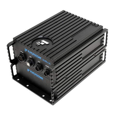
Futurecom DVR-LX User manual

Futurecom
Futurecom DVRS User manual

Futurecom
Futurecom 8A535X03 User manual

Futurecom
Futurecom Mobexcom P25 Operating instructions

Futurecom
Futurecom PDR8000 Quick reference guide

Futurecom
Futurecom Mobexcom P25 User manual