Tar River Implements BFM-105 User manual

Rev. 12/22
Rear Discharge Finishing Mower
BFM-105 & BFM-106
Operator’s Manual

2
BFM-100 Series Finish Mower
Page left blank intentionally

3
BFM-100 Series Finish Mower
TO THE DEALER:
Assembly and proper installation of this product is the responsibility of the Tar River dealer. Read manual
instructions and safety rules. Make sure all items on the Dealer’s Pre-Delivery and Delivery Check Lists in the
Owner’s/Operator’s Manual are completed before releasing equipment to the owner.
TO THE OWNER:
Read this manual before operating your Tar River equipment. The information presented will prepare you to
do a better and safer job. Keep this manual handy for ready reference. Require all operators to read this manual
carefully and become acquainted with all the adjustment and operating procedures before attempting to
operate. Replacement manuals can be obtained from your selling dealer. The equipment you have purchased
has been carefully engineered and manufactured to provide dependable and satisfactory use. Like all
mechanical products, it will require cleaning and upkeep. Lubricate the unit as specified. Observe all safety
information in this manual and safety decals on the equipment. For service, your authorized Tar River dealer
has trained mechanics, genuine Tar River service parts, and the necessary tools and equipment to handle all
your needs. Use only genuine Tar River service parts. Substitute parts will void the warranty and may not meet
standards required for safe and satisfactory operation.
Record your implement model and serial number in the space provide below. Your dealer will need this
information to give you prompt, efficient service.
Model Number: ______________________________________
Serial Number: _______________________________________
Date Purchased: ______________________________________

4
BFM-100 Series Finish Mower
Introduction …………………………………………………………………………………………….. 5
Technical Specifications ……………………………………………………………………………….. 5
Safety …………………………………………………………………………………………………… 6
Safety Signal Words ……………………………………………………………………………………. 6
General Safety Guidelines ……………………………………………………………………………… 7
Safety Decal Care ………………………………………………………………………………………. 7
Before Operation ……………………………………………………………………………………….. 8
During Operation ……………………………………………………………………………………….. 9
Highway And Transport Operations …………………………………………………………………… 10-11
Operating Instructions…………………………………………………………………………………... 12-16
Maintenance…………………………………………………………………………………………….. 17-18
Trouble Shooting……………………………………………………………………………………….. 19-20
Torque Specifications ………………………………………………………………………………….. 21
Parts Breakdown ……………………………………………………………………………………….. 23-29
Decals…………………………………………………………………………………………………… 30-31
Warranty ………………………………………………………………………………………………... 32
Table of Contents

5
BFM-100 Series Finish Mower
Thank you for purchasing your BFM-100 Series Finishing Mower. The BFM-100 Series Finishing Mowers are
great for compact tractors maintaining home estates and light landscaping.
Technical Specifications
• Solid rubber tires
• Rear discharge
• Floating hitch
• Easy cutting height adjustment
• Easy belt tension adjustment
• Powder coat paint
• Category 1 hitch
BFM-105 BFM-106
Weight 435 lbs. 544 lbs.
Req. HP 15-30 15-30
Working width 58” 71”
Overall width 59” 72”
Number of blades 33
Grass discharge Rear discharge Rear discharge
Tires Solid rubber Solid rubber
Introduction

6
BFM-100 Series Finish Mower
Safety
It is important that you read the entire manual and to become familiar with this product before you begin using
it. This product is designed for certain applications only. The manufacturer cannot be responsible for issues
arising from modification. We strongly recommend this product not be modified and /or used for any
application other than that for which it is designed. If you have any questions relative to a particular
application, DO NOT use the product until you have first contacted us to determine if it can or should be
performed on the product.
Read and understand this manual and all safety signs before operating and maintaining . Review the safety
instructions and precautions annually.
Safety Signal Words
TAKE NOTE! This safety alert symbol found though out this manual is used to call you attention to
instructions involving you personal safety and the safety of others. Failure to follow these instructions
can result in injury or death.
This symbol means:
Attention!
Become alert!
Your safety is involved!
Note the use of the signal words, DANGER, WARNING and CAUTION with the safety
messages. The appropriate signal word for each has been selected using the following guidelines:
DANGER: Indicates an imminently hazardous situation that, if not avoided, will result in death or
serious injury. This signal word is to be limited to the most extreme situations typically for machine
components which, for functional purposes, cannot be guarded.
WARNING: Indicates a potentially hazardous situation that, if not avoided, could result in death or
serious injury, and includes hazards that are exposed when guards are removed. It may also be used
to alert against unsafe practices.
CAUTION: Indicates a potentially hazardous situation that, if not avoided, may result in minor or
moderate injury. It may also be used to alert against unsafe practices.
Important Safety Information

7
BFM-100 Series Finish Mower
General Safety Guidelines
Safety of the operator is one of the main concerns in designing and developing a new piece of equipment.
Designers and manufacturers build in as many safety features as possible. However, every year many accidents
occur which could have been avoided by a few seconds of thought and a more careful approach to handling
equipment. You, the operator, can avoid many accidents by observing the following precautions in this section.
To avoid personal injury, study the following precautions and insist those working with you, or for you, follow
them.
Replace any DANGER, WARNING, CAUTION or instruction safety decal that is not readable or is missing.
Location of such decals are indicated in this manual. Do not attempt to operate this equipment under the
influence of drugs or alcohol.
Review the safety instructions with all users annually.
This equipment is dangerous to children and persons unfamiliar with its operation. The operator should be a
responsible adult familiar with farm machinery and trained in this equipment’s operations. Do not allow
persons to operate or assemble this unit until they have read this manual and have developed a
thorough understanding of the safety precautions and of how it works.
To prevent injury of death, use a tractor equipped with a Roll Over Protection System (ROPS). Do not paint
over, remove or deface any signs or warning decals on your equipment. Observe all safety signs and practice
the instructions on them.
Never exceed the limits of a piece of machinery. If its ability to do a job, or to do so safely, is in question,
Don’t try it!
• Keep safety signs clean and legible at all times.
• Replace safety signs that are missing or have become illegible.
• Replaced parts that displayed a safety sign should also display the current safety sign
• Safety signs are available from your Distributor or Dealer Parts Department or the factory.
Safety Decal Care
Important Safety Information

8
BFM-100 Series Finish Mower
How to install Safety Signs:
• Be sure that the installation area is clean and dry.
• Decide on the exact position before you remove the backing paper.
• Remove the smallest portion of the split backing paper.
• Align the decal over the specified area and carefully press the small portion with the exposed sticky
backing in place.
• Slowly peel back the remaining paper and carefully smooth the remaining portion of the decal in place.
• Small air pockets can be pierced with a pin and smoothed out using the piece of decal backing paper.
• Carefully study and understand this manual.
• Do not wear loose-fitting clothing, which may catch in moving parts.
• Always wear protective clothing and substantial shoes.
• Assure that all tires are inflated evenly.
• Give the unit a visual inspection for any loose bolts, worn parts or cracked welds, and make necessary
repairs. Follow the maintenance safety instructions included with this manual.
• Be sure that there are no tools lying on or in the equipment.
• Do not use the unit until you are sure that the area is clear, especially of children and animals.
• Don’t hurry the learning process or take the unit for granted. Ease into it and become familiar with your
new equipment.
• Practice operation of your equipment and its attachments. Completely familiarize yourself and other
operators with its operation before using.
• Use a tractor equipped with a Roll Over Protection System (ROPS) and fasten your seat belt prior to
starting engine.
• The manufacturer does not recommend usage of tractor with ROPS removed.
• Move tractor wheels to the widest recommended settings to increase stability.
• Securely attach to towing unit. Use a high strength, appropriately sized hitch pin with a mechanical retainer
and attach safety chain.
• Do not allow anyone to stand between the tongue or hitch and the towing vehicle when backing up to the
equipment.
• Do not use the unit until you are sure that the area is clear, especially of children and animals.
Before Operation
Important Safety Information

9
BFM-100 Series Finish Mower
• Children should not be allowed on the machine.
• Clear the area of small children and bystanders before moving the machine.
• If using a towing unit, securely attach machine by using a hardened 3/4” pin, a metal retainer, and safety
chains if required. Shift towing unit to a lower gear before going down steep downgrades, thus using the
engine as a retarding force. Keep towing vehicle in gear at all times. Slow down for corners and rough
terrain.
• Make sure you are in compliance with all local and state regulations regarding transporting equipment on
public roads and highways. Lights and slow moving signs must be clean and visible by overtaking or
oncoming traffic when machine is transported.
• Beware of bystanders, particularly children! Always look around to make sure that it is safe to start the
engine of the towing vehicle or move the unit. This is particularly important with higher noise levels and
quiet cabs, as you may not hear people shouting.
• NO PASSENGERS ALLOWED! Do not carry passengers anywhere on, or in, the tractor or equipment,
except as required for operation.
• Keep hands and clothing clear of moving parts.
• Do not clean, lubricate or adjust your equipment while it is moving.
• When halting operation, even periodically, set the tractor or towing vehicle brakes, disengage the PTO,
shut off the engine and remove the ignition key.
• Be especially observant of the operating area and terrain. Watch for holes, rocks or hidden hazards. Always
inspect the area prior to operation.
• DO NOT operate near the edge of drop-offs or banks.
• DO NOT operate on steep slopes as overturns may result.
• Operate up and down (not across) intermediate slopes. Avoid sudden starts and stops.
During Operation
Important Safety Information

10
BFM-100 Series Finish Mower
• Adopt safe driving practices.
• Keep the brake pedals latched together at all times. Never use independent braking with machine in tow
as loss of control and/or upset of unit can result.
• Always drive at a safe speed relative to local conditions and ensure that your speed is low enough for an
emergency stop to be safe and secure. Keep speed at a minimum.
• Reduce speed prior to turns to avoid the risk of overturning.
• Avoid sudden uphill turns on steep slopes.
• Always keep the tractor or towing vehicle in gear to provide engine braking when going downhill. Do not
coast.
• Do not drink and drive!
• Comply with state and local laws governing highway safety and movement of farm machinery on public
roads.
• Use approved accessory lighting, flags and necessary warning devices to protect operators of other vehicles
on the highway during daylight and nighttime transport. Various safety lights and devices are available
from your dealer.
• The use of flashing amber lights is acceptable in most localities. However, some localities prohibit their
use. Local laws should be checked for all highway and marking requirements.
• When driving the tractor and equipment on the road or highway under 40 kph (20 mph) at night or during
the day, use the amber warning lights and a slow moving vehicle (SMV) identification emblem.
• Plan your route to avoid heavy traffic.
• Be a safe and courteous driver. Always yield to oncoming traffic in all situations, including narrow
bridges, intersections, etc.
• Be observant of bridge loading ratings. Do not cross bridges rated at lower than the gross weight at which
you are operating.
• Watch for obstructions overhead and to the side while transporting.
• Always operate in a position to provide maximum visibility at all times. Make allowances for increased
length and weight of the equipment when making turns, stopping the unit, etc.
• Pick the most level route when transporting across fields. Avoid the edges of ditches or gullies and steep
hillsides.
• Be extra careful when working in inclines.
Highway and Transport Operations
Important Safety Information

11
BFM-100 Series Finish Mower
• Maneuver the tractor or towing vehicle at safe speeds.
• Avoid overhead wires or other obstacles. Contact with overhead lines could cause serious injury or death.
• Avoid loose fill, rocks and holes, they can be dangerous for equipment operation or movement.
• Allow for unit length when making turns,
• Operate the towing vehicle from the operator’s seat only.
• Never stand alongside of unit with engine running or attempt to start engine and/or operate machine while
standing alongside of unit.
• Never leave running equipment attachments unattended.
• As a precaution, always recheck the hardware on equipment following every 100 hours of operation.
Correct all problems. Follow the maintenance safety procedures.
Highway and Transport Operations
Important Safety Information
12
BFM-100 Series Finish Mower
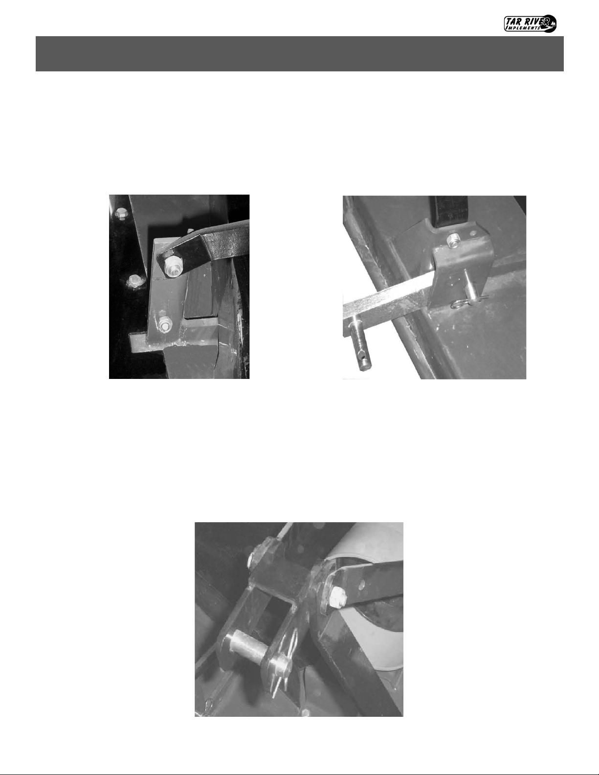
Assembly
Step 1: Attach the rear brace bars to the lugs on the rear of deck with M12-1.75x40 hex bolt and M12-1.75
locking nut. Attach the A-frame bars to the lugs on the front of the mower deck with M12-1.75x40 bolts and
M12-1.75 locking nuts.
Step 2: Connect all braces at the top of the A-frame with a M12 bolt, spacer, hitch connection and locking nut.
Operating Instructions
Rear Brace Front Brace
13
BFM-100 Series Finish Mower
Assembly
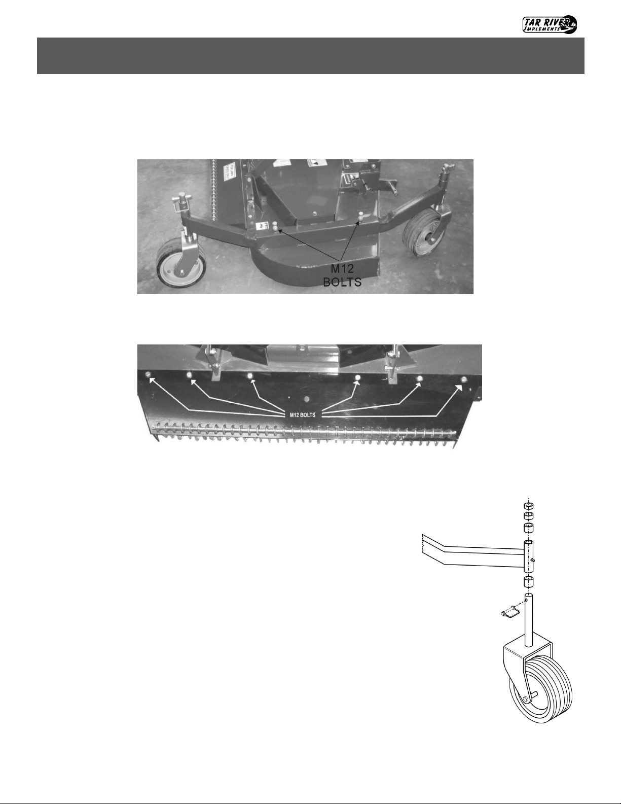
Step 3: Install the wheel support braces with M12 bolt and locking nuts as shown below.
Step 4: Install rear discharge chute and safety chains using M12 bolts and locking nuts as shown below.
Step 5: Cutting height adjustment.
Support the unit securely when changing wheel height spacers.
Remove the pin from the wheel yoke and remove wheel yoke from wheel
arm. Increase mower cutting height by placing spacers below the wheel arm.
Decrease cutting height by placing spacers above the wheel arm. Re-attach
wheel yoke and secure with pin. Each wheel yoke must have the same
combination of spacers in order to cut even.
Operating Instructions

14
BFM-100 Series Finish Mower
Assembly Cont.
Place the covers (13) on the belts, tighten the handles on the frame (14) and on the gearbox support (15). Attach the
PTO shield (16) by means of four screws (17) and the washers (18).
Install the uprights (19) on the machine and insert the bolts (21), and relative nuts (22). Install the tie rods (20) on
the machine and insert the bolts (23), with relative nuts (24). Place the top link (25) on both tie-rods and uprights,
by inserting the spacer (26) between the top link and the tie-rods; finally tighten the screw (27) with the nut (28)
and the washer (29). Make sure that the top link turns freely on the bolt. Finally tighten the bolts (21) with the nuts
(22) and the bolts (23) with the nuts (24). Install the lower hitches (30) on the supports (31); adjust the length and
install the pins (32) anchoring them by means of the split pins (33).
Operating Instructions

15
BFM-100 Series Finish Mower
Attaching the BFM Series Finish Mower
Carefully read this instruction manual and the manuals of the tractor and
PTO shaft manufacturer. All mowers are built to be attached to any tractor
equipped with a three-point lift of the correct category and with suitable
ball ends.
Before attaching the equipment to the tractor, make sure that the ground is
smooth and flat and that nobody is standing between the tractor and the
mower; slowly move the tractor towards the mower by aligning the tractor
lifter arms with the two mower coupling side pins; turn the engine off and
pull the brake.
It is possible to adjust the attachment position by releasing the pins, A
and modifying the position of the plates B.
Connect the tractor top link to the third upper point by removing the pin located between the two plates, inserting
the top link and securing it by means of the pin.
Adjust the top link so that the upper part of the frame is parallel to the ground. Block all the linking parts by means
of the sway chains or arms.
Make sure that the central unit axis (case/bevel gear pair) is parallel to the ground, thus minimizing the stresses on
the power take off and increasing the working life of the equipment.
Before installing the PTO shaft make sure that the RPM rating and the direction of rotation match those of the
tractor. Carefully read the PTO shaft and tractor instructions.
Furthermore, accurately read the instructions of the manufacturer of the PTO shaft and of the tractor. Before
starting any activity, make sure that the guards are installed on the power take off of the tractor and PTO shaft.
Make sure that they cover the PTO shaft throughout its length.
Operating Instructions
Warning: When attaching the BFM Series Finish Mower, Never allow anyone to stand
between the BFM Series Finish Mower and the tractor. Serious injury or death can occur!
Tractor Top Link

16
BFM-100 Series Finish Mower
Before attaching the rotary tiller to the tractor, check the unit to ensure there is oil
in the top and side gearbox. See Maintenance section for lubricant specifications.
Operating Instructions
Operating InstructionsAttaching to TractorAttaching PTO Shaft
Attaching the PTO shaft:
Before installing the PTO shaft make sure that the RPM rating and the direction of rotation match those of the
tractor. Carefully read the PTO shaft and tractor instructions. Before operation, make sure that the guards are
installed on the power take off of the tractor and PTO shaft. Make sure that they cover the PTO shaft
throughout its length. Note: The PTO shaft may be too long and require shortening. See “Shortening a PTO
driveline” below.
Press the locking pin on the PTO yoke and slide yoke on to the PTO of the tractor until the pin seats. Pull on
PTO shaft to make certain it is locked in place. Repeat the procedure for the machine end. Attach the PTO
cover’s safety chains to a stationary part of the tractor. Leave some slack in the chain to accommodate
movement.
Shortening a PTO driveline:
1. With the machine attached to the tractor’s 3-
point hitch, and the PTO shaft not installed,
separate the PTO shaft. Attach the machine
end to the machine and the other end to the
tractor PTO input shaft.
2. Raise the machine by using the tractor’s
hydraulic 3-point hitch to its maximum lift
height.
3. Hold the half shafts next to each other and
mark them so each end is approximately
1/2” from hitting the end of the telescopic
profiles.
4. Shorten the inner and outer guard tubes
equally.
5. Shorten the inner and outer profiles by the same length as the guard tubes. Using a rattail file, round off all
sharp edges and burrs. Grease the telescopic profile generously before reassembling.
When fully extended, the tubes must overlap by at least 1/3 of the length of the pipes
(LT). When retracted, the min. acceptable clearance is 1-2 cm (3/8”-3/4”)
Operating Instructions
Scan the QR code below for more detailed information on PTO installation.

17
BFM-100 Series Finish Mower
Operating Instructions
Operating InstructionsAttaching to TractorAttaching PTO Shaft
Cutting Height Adjustment:
The cutting height of the equipment depends on the position of the wheels.
If the wheels are raised, the cutting height increases; if the wheels are
lowered, the cutting height decreases.
Make sure that the wheels are set at the same height on both sides.
To adjust the cutting height on the mowers loosen and re- move pin A and
adjust the wheels height according to the bushing B. When the adjustment
is completed, reinsert the pin A.
Adjusting Belt Tension:
In the mowers it is necessary to adjust the belt tension as they stretch;
the correct belts tensioning ensures that the machine works correctly.
To adjust the belts tension:
Remove the two Belt Shields (A).
Loosen the Nuts (B) holding the gearbox in place just enough to allow
the gearbox to be able to move. Turn the bolt C to adjust the tension of
the belts; if you turn the bolt in clockwise direction the belts are
tightened, while turning it counter clockwise they are loosened; when
the belt is tensioned correctly the belt should be able to deflect a
maximum of 10 mm (3/8”). Retighten the Nuts (B). Replace Belt
Shields (A).
Operating Instructions
Caution: These activities must be carried out with the engine off, the power take off
disengaged and the hand brake applied. If needed, lift the equipment and place it on
supports, thus preventing any injuries that might be caused by a sudden fall of the
equipment.
18
BFM-100 Series Finish Mower
Operating Instructions
Operating InstructionsAttaching to TractorAttaching PTO Shaft
Maintenance:
Maintenance is crucial for the working life and efficiency of any agricultural equipment. If the equipment is
properly maintained and operated, a long working life and operator safety are assured.
The maintenance intervals indicated in this booklet are provided as a mere reference and are related to normal
working conditions; changes may occur depending on the type of activities, environmental dust, seasonal
factors, etc.
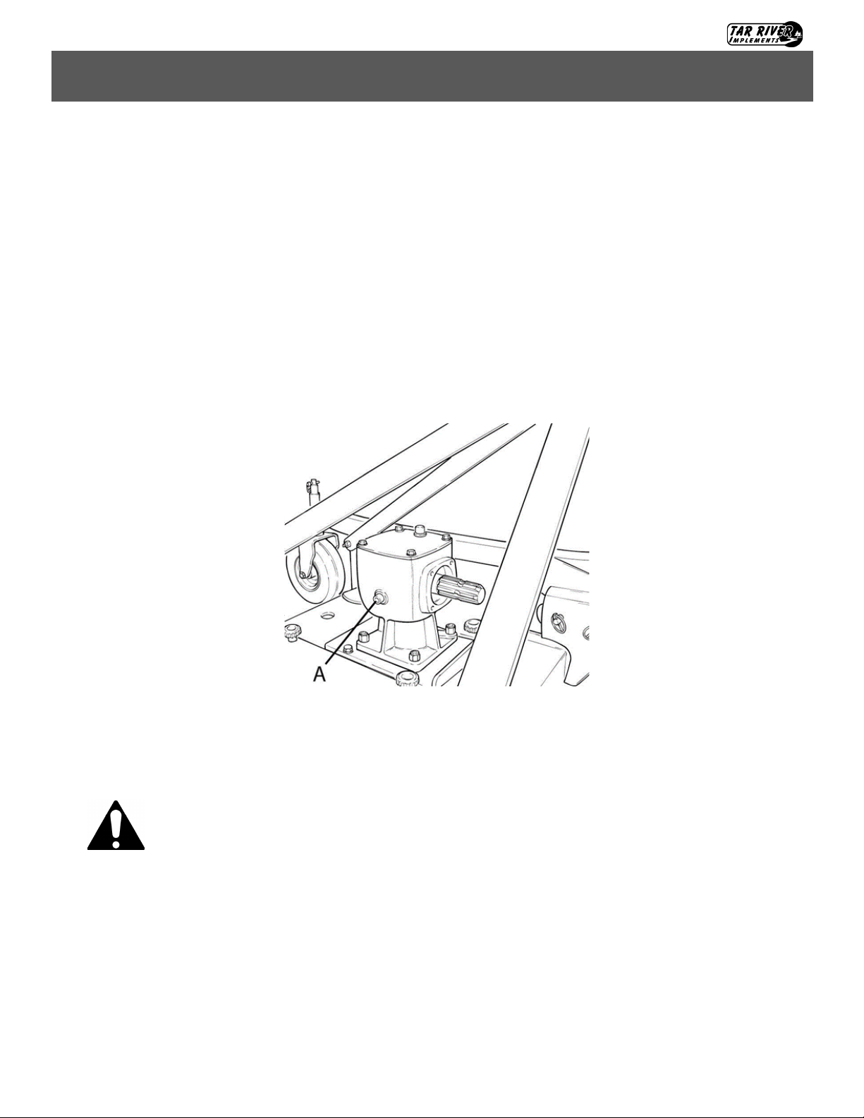
First check
After 50 working hours, check the oil in the gearbox (A) and make sure that all the screws and bolts are
tightened.
Maintenance
Caution: Before injecting lubricating grease into the grease fittings, clean the fittings
to prevent mud, dust, or any other foreign matter from contaminating the grease and
reducing the lubrication effect.
When adding or changing the oil, use the same type of oil to prevent mixing oils with
different features.
All maintenance activities must be carried out with the mower resting horizontally
on the ground, with the equipment off and not overheated.
After using the equipment for a few hours, make sure that all the bolts are tightened;
regularly check all the machine guards.

19
BFM-100 Series Finish Mower
Operating Instructions
Operating InstructionsAttaching to TractorAttaching PTO Shaft
Every 20 working hours
Lubricate the pulley support bearing (C ).
Every 30 working hours
Check belt tensioning.
Every 40 working hours
Lubricate the wheel supports (A).
After the first 50 working hours and, later, every 800 working hours
Replace the oil in the gearbox. Use SAE EP 80W90.
BLADE REPLACEMENT
For optimal results, check the mower blades frequently, especially if cutting in sandy or rocky soil. Dull, worn
blades will cut grass uneven and streak.
Take any and all measures to prevent accidental machine start-up.
Place the equipment on sturdy supports.
Maintenance
Danger: Before replacing the blades, turn the tractor engine off, pull the parking
brake, disengage the power take off, raise the mower using the tractor lift, and install
supports to prevent accidental dropping of the machine.
Version 2: Blade w/ Center Bolt
Remove the center bolt by
turning the center bolt
counter clockwise. Next
remove the remove the
blade adaptor plate
hardware. Replace with
new OEM blade and
hardware. Inspect the
condition of the spindle at
this time. Replace if
necessary.
Version 1: Blade w/ Center Nut
Remove the lock nut by
turning the center nut
counter clockwise.
Replace with new OEM
blade and hardware.
Inspect the condition of the
spindle at this time.
Replace if necessary.

20
BFM-100 Series Finish Mower
Operating Instructions
Operating InstructionsAttaching to TractorAttaching PTO ShaftTrouble Shooting
Problem Possible Cause Solution
Streaking
Slow blade p speed Operate PTO at 540 RPM
Worn blade ps Replace with new OEM blades
Dull blades
Sharpen, balance old blades or replace with
new OEM blades
Blades unable to cut the part of grass
pressed down by tractor's re path or
mower's casters
Slow tractor's ground speed but maintain
540 RPM PTO speed
Ground speed too fast Shi tractor to a lower gear
Drive belt loose Tighten per instrucons on page 16
Blade loose on spindle Tighten blade nut to proper specs, page 18
Condions too wet for mowing Allow grass to dry before mowing
Grass discharges from mower
unevenly or bunches along a
swath
Material too high and too thick
Slow tractor’s ground speed but maintain
540 RPM PTO speed. Make two passes. Raise
the mower for the rst pass and lower to the
desired cung height for the second and cut
at 90 degrees to the rst pass. Cut a paral
swath only.
Grass wet Allow grass to dry before mowing. Slow trac-
tor’s ground speed but maintain 540 RPM
PTO speed.
Excessive vibraon
Driveline broken or bent Replace with OEM driveline
Broken/bent blade Replace with OEM blade
Worn/unbalanced blade Sharpen, balance or replace with OEM blade
Bent/broken sheave Replace with correct specied part
Debris caught on blade Clean blade, spindle, inspect blade and re-
place with OEM blade if necessary
Belt slipping
Belt loose Tighten or replace with OEM belt
Belt glazed Use belt dressing or replace with OEM belt
Mower is overloading, grass is too tall or
heavy
Slow tractor’s ground speed but maintain
540 RPM PTO speed. Make two passes. Raise
the mower for the rst pass and lower to the
desired cung height for the second and cut
at 90 degrees to the rst pass. Cut a paral
swath only.
Oil on belt from over lubricaon
Clean lubricant from belt and sheaves with a
clean rag, Replace oil soaked belts. Be sure to
follow operator’s manual recommendaons.
Belt hung or rubbing
Check belt for free travel in pulleys. Check
under mower deck and spindles for debris or
other foreign material and remove if any is
present.
This manual suits for next models
1
Table of contents
Popular Lawn Mower manuals by other brands

Husqvarna
Husqvarna Rider 18 ProFlex Operator's manual

Toro
Toro Eurocycler 21080 Operator's manual

Scag Power Equipment
Scag Power Equipment Turf Tiger Diesel Powered STT61V-25KBD Operator's manual

Husqvarna
Husqvarna 7021R owner's manual

Craftsman
Craftsman 25380 instruction manual

GreenWorks
GreenWorks MO10B00 Operator's manual


