Toro TimeCutter 79335 User manual

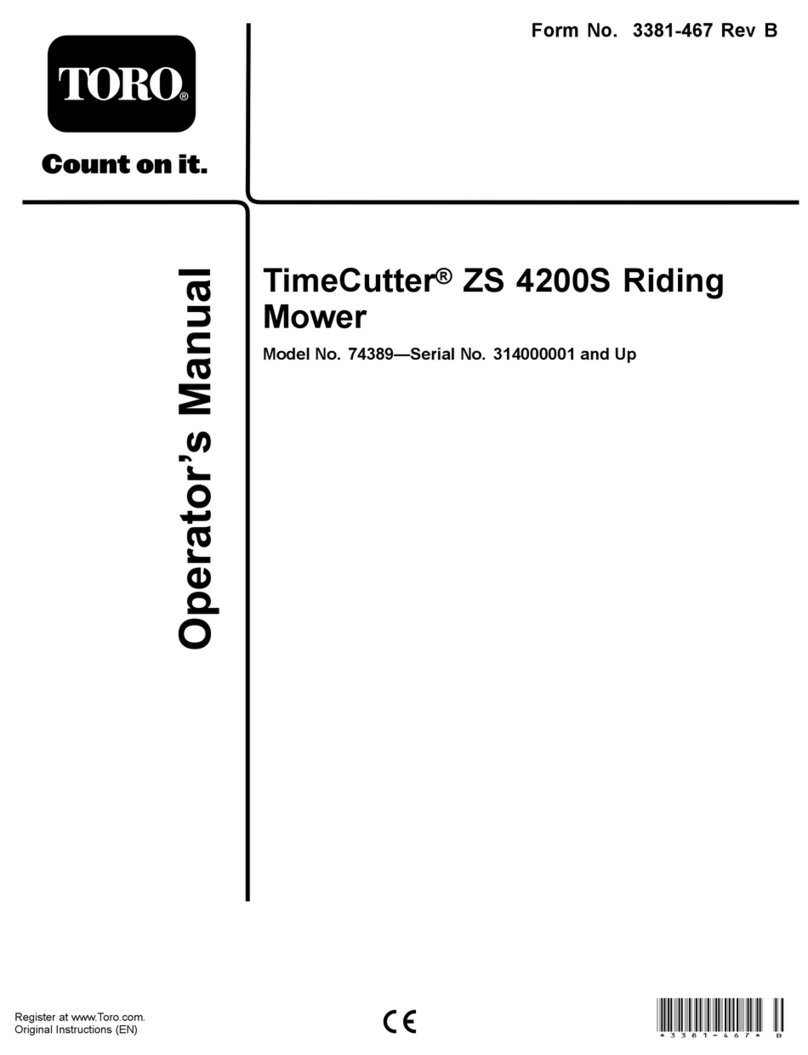
FormNo.3375-960RevB
50inBagger
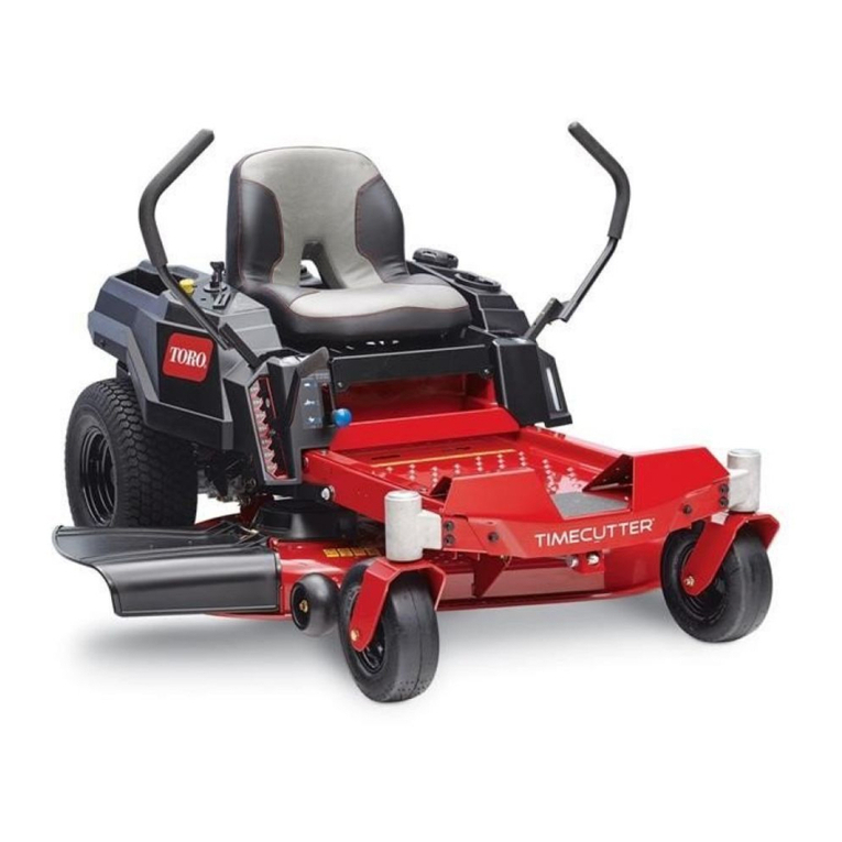
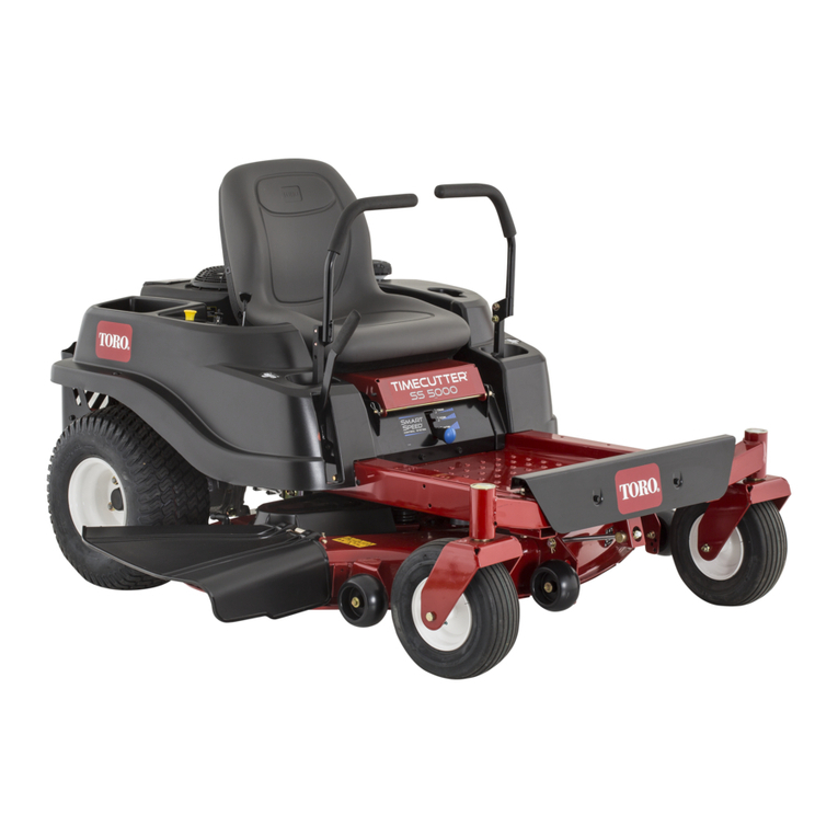
TimeCutter®RidingMower
ModelNo.79335—SerialNo.313000001andUp
Registeratwww.T oro.com.
OriginalInstructions(EN)*3375-960*B

WARNING
CALIFORNIA
Proposition65Warning
Thisproductcontainsachemicalorchemicals
knowntotheStateofCaliforniatocausecancer,
birthdefects,orreproductiveharm.
Introduction
Readthisinformationcarefullytolearnhowtooperateand
maintainyourproductproperlyandtoavoidinjuryand
productdamage.Youareresponsibleforoperatingthe
productproperlyandsafely.
YoumaycontactTorodirectlyatwww.Toro.comforproduct
andaccessoryinformation,helpndingadealer,ortoregister
yourproduct.
Wheneveryouneedservice,genuineToroparts,oradditional
information,contactanAuthorizedServiceDealerorToro
CustomerServiceandhavethemodelandserialnumbersof
yourproductready.Figure1identiesthelocationofthe
modelandserialnumbersontheproduct.Writethenumbers
inthespaceprovided.
Figure1
1.Modelandserialnumberlocation
ModelNo.
SerialNo.
Thismanualidentiespotentialhazardsandhassafety
messagesidentiedbythesafetyalertsymbol(Figure2),
whichsignalsahazardthatmaycauseseriousinjuryordeath
ifyoudonotfollowtherecommendedprecautions.
Figure2
1.Safetyalertsymbol
Thismanualuses2otherwordstohighlightinformation.
Importantcallsattentiontospecialmechanicalinformation
andNoteemphasizesgeneralinformationworthyofspecial
attention.
Contents
Introduction..................................................................2
Safety...........................................................................3
TowingSafety.........................................................3
SafetyandInstructionalDecals.................................4
Setup............................................................................5
1InstallingtheWeight..............................................6
2InstallingtheEngineGuard....................................8
3InstallingtheBaggerFrame....................................8
4AssemblingtheBaggerTop...................................10
5InstallingtheBaggerTop......................................10
6InstallingtheCutoffBafe....................................11
7InstallingtheChute..............................................12
8ConnectingwiththeDischargeTube......................13
Operation....................................................................14
EmptyingtheGrassBags.........................................14
ClearingObstructionsfromtheBagger.....................14
RemovingtheBagger..............................................15
UsingtheDrawBar................................................15
OperatingTips......................................................15
Maintenance.................................................................17
RecommendedMaintenanceSchedule(s)......................17
InspectingtheBaggerAttachment............................17
InspectingtheMowerBlades...................................17
CaringfortheGrassBags........................................18
CleaningtheBaggerAttachment..............................18
Storage........................................................................18
StoringtheBaggerAttachment.................................18
©2013—TheToro®Company
8111LyndaleAvenueSouth
Bloomington,MN554202
Contactusatwww.Toro.com.
PrintedintheUSA.
AllRightsReserved

Safety
DANGER
Enginescanbecomehotwhentheyareoperating.
Severeburnscanoccurfromcontactinghot
surfaces.
Allowengines,especiallythemufer,tocoolbefore
touching.
DANGER
Debris,suchasleaves,grass,orbrushcancatch
re.Areintheengineareacancausepersonal
injuryandpropertydamage.
•Keeptheengineandmuferareafreeofdebris
accumulation.
•Takecarewhenopeningthebaggercoverto
keepdebrisfromfallingontotheengineand
muferarea.
•Allowthemachinetocoolbeforestoringit.
ThefollowinglistcontainssafetyinformationspecictoToro
productsandothersafetyinformationyoumustknow .
•Becomefamiliarwiththesafeoperationoftheequipment,
withtheoperatorcontrols,andsafetysigns.
•Useextracarewithgrasscatchersorotherattachments.
Thesecanchangetheoperatingcharacteristicsandthe
stabilityofthemachine.
•Followthemanufacturer'srecommendationsforadding
orremovingwheelweightsorcounterweightstoimprove
stability.
•Donotuseagrasscatcheronsteepslopes.Aheavy
grasscatchercouldcauselossofcontroloroverturnthe
machine.
•Slowdownanduseextracareonhillsides.Besureto
travelintherecommendeddirectiononhillsides.Turf
conditionscanaffectthemachine'sstability.Useextreme
cautionwhileoperatingneardrop-offs.
•Keepallmovementonslopesslowandgradual.Donot
makesuddenchangesinspeed,directionsorturning.
•Thegrasscatchercanobstructtheviewtotherear.Use
extracarewhenoperatinginreverse.
•Usecarewhenloadingorunloadingthemachineintoa
trailerortruck.
•Neveroperatewiththedischargedeectorraised,
removedoraltered,unlessusingagrasscatcher.
•Keephandsandfeetawayfrommovingparts.Donot
makeadjustmentswiththeenginerunning.
•Stoponlevelground,disengagedrives,chockorblock
wheels,shutoffenginebeforeleavingtheoperator's
positionforanyreasonincludingemptyingthegrass
catcheroruncloggingthechute.
•Ifyouremovethegrasscatcher,besuretoinstallany
dischargedeectororguardthatmighthavebeen
removedtoinstallthegrasscatcher.Donotoperatethe
mowerwithouteithertheentiregrasscatcherorthegrass
deectorinplace.
•Stoptheenginebeforeremovingthegrasscatcheror
uncloggingthechute.
•Donotleavegrassingrasscatcherforextendedperiods
oftime.
•Grasscatchercomponentsaresubjecttowear,damage
anddeterioration,whichcouldexposemovingpartsor
allowobjectstobethrown.Frequentlycheckcomponents
andreplacewithmanufacturer'srecommendedparts,
whennecessary.
TowingSafety
•Donotattachtowedequipmentexceptatthehitchpoint.
•Followtheattachmentmanufacturer'srecommendation
forweightlimitsfortowedequipmentandtowingon
slopes.
•Neverallowchildrenorothersinorontowedequipment.
•Onslopes,theweightofthetowedequipmentmaycause
lossoftractionandlossofcontrol.Reducetowedweight
andslowdown.
•Stoppingdistanceincreaseswiththeweightofthetowed
load.Travelslowlyandallowextradistancetostop.
•Makewideturnstokeeptheattachmentclearofthe
machine.
•Donottowaloadthatweighsmorethanthetowing
machine.
3
SafetyandInstructionalDecals
Safetydecalsandinstructionsareeasilyvisibletotheoperatorandarelocatednearanyareaofpotential
danger.Replaceanydecalthatisdamagedorlost.
109-6809
1.Crushinghazardofhand—donotremovethewholebaggerfromthemachine;openthebaggertopandthenremovethebag(s)
fromthebagger.Donotremovethebaggertopwhenitisclosed;openthebaggertopandthenremoveit.
109-7076
4

Setup
LooseParts
Usethechartbelowtoverifythatallpartshavebeenshipped.
ProcedureDescriptionQty.Use
Bolt(3/8x1-1/4inches)4
Locknut(3/8inch)4
Weightmountingbracket,left1
Weightmountingbracket,right1
Washers4
Weightholdingbracket1
Bolt(3/8x1inch)2
Flatweight1
Suitcaseweight1
1
Keyedcrossbar1
Installtheweight.
Engineguard1
2Selftappingscrew(5/16x3/4inch)4Installtheengineguard.
Baggerframesupportbracket1
Supportspacerplate1
Selftappingscrew(5/16x3/4inch)2
Bolt(5/16x1inch)2
Locknut(5/16inch)4
Angledbracket1
Carriagebolt(5/16x3/4inch)2
Baggerframe1
Clevispin(1/2x2-1/4inch)1
Hairpincotter5
Rod2
3
Washer4
Installthebaggerframe.
Baggertop1
4Baggerscreen1Assemblethebaggertop.
GrassBag2
5Upperbaggertube1Installthebaggertop.
6Nopartsrequired–Installthecutoffbafe.
7Chute1Installthechute.
8Dischargetube1Connectwiththedischargetube.
5

1
InstallingtheWeight
Partsneededforthisprocedure:
4Bolt(3/8x1-1/4inches)
4Locknut(3/8inch)
1Weightmountingbracket,left
1Weightmountingbracket,right
4Washers
1Weightholdingbracket
2Bolt(3/8x1inch)
1Flatweight
1Suitcaseweight
1Keyedcrossbar
Procedure
CAUTION
Thebaggerchangestheweightdistributionofthe
machine.Operatingthemachinewithoutthefront
weightsmaycauseanunstableconditionwhich
couldresultinalossofcontrol.
Ensurethefrontweightsareproperlyinstalled
beforeoperatingthemachinewiththebagger
attachment.
1.Locatetheforwardboltsontheundersideoftheframe
(Figure3andFigure4).Removethetwobolts(3/8x1
inch)andtwolocknuts(3/8inch).Retainthelocknuts.
G014875
1
2
3
4
Figure3
1.Frontrightcaster(castor
forkandwheelnotshown
forclarity)
3.Bolt(3/8x1inch)
2.Forwardhole,rightside4.Locknut(3/8inch)
G014877
1
23
4
Figure4
1.Locknut(3/8inch)3.Frontleftcaster(castor
forkandwheelnotshown
forclarity)
2.Forwardhole,leftside4.Bolt(3/8x1inch)
2.Locatetheleftandrightweightmountingbracketsin
looseparts.Startbyinstallingtheleftbrackettothe
undersideoftheframe.
3.Securethebrackettotheframeusingtwobolts(3/8
x1-1/4inches),twowashersandtwolocknuts(3/8
inch)(Figure5).Onelocknutisfromloosepartsand
theotherisreusedfromearlierremoval.
6

G014878
1
23
4
5
6
7
8
Figure5
1.Locknut(3/8inch),existing5.Hole,existinginframe
2.Forwardhole,leftside6.Washer
3.Frontleftcaster(castor
forkandwheelnotshown
forclarity)
7.Bolt(3/8x1-1/4inches)
4.Locknut(3/8inch),loose
parts
8.Leftmountingbracket
4.Ontherightsideofthemachineinstalltherightweight
mountingbracket.
•Formachineswithoutafootassistliftpedal:secure
thebracketusingtwobolts(3/8x1-1/4inches),
twowashersandtwolocknuts(3/8inch)(Figure
6).Onelocknutisfromloosepartsandtheother
isreusedfromearlierremoval.
G014876
1
2
3
4
5
6
7
8
Figure6
1.Frontrightcaster(castor
forkandwheelnotshown
forclarity)
5.Bolt(3/8x1-1/4inches)
2.Forwardhole,rightside6.Washer
3.Locknut(3/8inch),existing7.Hole,existinginframe
4.Rightmountingbracket8.Locknut(3/8inch),loose
parts
•Formachineswithafootassistliftpedal:The
washerswillnotbeneeded.Instead,remove
theforwardfastenersinthefootassistliftpedal
bracket.Securethebracketusingtwoboltsand
twolocknuts(Figure7).Onelocknutisfromloose
partsandtheotherisreusedfromearlierremoval.
G014883
1
2
3
4
5
6
7
8
Figure7
1.Frontrightcaster(castor
forkandwheelnotshown
forclarity)
5.Bolt(3/8x1-1/4inches)
2.Forwardhole,rightside6.Footassistliftpedal
bracket
3.Locknut(3/8inch),existing7.Hole,existinginbracket
4.Rightmountingbracket8.Locknut(3/8inch),loose
parts
5.Installtheweightholdingbrackettothemounting
brackets(Figure8).Aligntheoutboardholesinthe
bracketwiththemountingbracketsinstalledpreviously.
Makesurethebracketiscenteredontheframe.Secure
withtwobolts(3/8x1inch)andtwolocknuts(3/8
inch).
G014879 12
3
4
5
Figure8
1.Locknut(3/8inch)4.Bolt(3/8x1inch)
2.Weightholdingbracket5.Rightmountingbracket
3.Leftmountingbracket
7

6.Installaatweighttotheholdingbracketandmoveit
rearward,ushwiththebracket(Figure9).
G014880
1
2
3
Figure9
1.Keyedcrossbar3.Suitcaseweight
2.Flatweight
7.Installasuitcaseweightinfrontoftheatweight
(Figure9).
8.Securetheweightstothebracketwithakeyedcross
bar(Figure9).Installthebarandrotateit90degrees
downwardtolockitinplace.
9.Onceallweightsandbracketshavebeeninstalled,go
backandcheckthatallfastenersaretight.Tightenas
necessary.
Important:Wheneveryouremovethebagger
attachment,remembertoremovethefrontweightsto
returntheproperstabilitytothemachine.
2
InstallingtheEngineGuard
Partsneededforthisprocedure:
1Engineguard
4Selftappingscrew(5/16x3/4inch)
Procedure
Note:Certainmodelswillhaveanengineguardalready
installed.Ifequipped,proceedtothenextprocedure.
CAUTION
Enginecomponentswillbehotifthemachinehas
beenrunning.Ifyoucontactorcomenearanyhot
components,youmaybeburned.
Allowthemachinetocoolbeforeinstallingthiskit.
1.Parkthemachineonalevelsurfaceanddisengagethe
bladecontrolswitch.
2.Movethemotioncontrolleversoutwardtotheneutral
lockposition,stoptheengine,removethekeyand
waitforallmovingpartstostopbeforeleavingthe
operatingposition.
3.Installtheengineguardtotheframebehindtheengine
(Figure10).Aligntheholesinthetabsontheguard
withtheexistingholesintherearframe.
4.Securetheguardtotheframewithfourselftapping
screws(5/16x3/4inch)asshowninFigure10.
Figure10
1.Selftappingscrew(5/16x
3/4inch)
3.Existingholeinrearframe
2.Rearguard4.Rearframe
8

3
InstallingtheBaggerFrame
Partsneededforthisprocedure:
1Baggerframesupportbracket
1Supportspacerplate
2Selftappingscrew(5/16x3/4inch)
2Bolt(5/16x1inch)
4Locknut(5/16inch)
1Angledbracket
2Carriagebolt(5/16x3/4inch)
1Baggerframe
1Clevispin(1/2x2-1/4inch)
5Hairpincotter
2Rod
4Washer
Procedure
1.Locatethebaggerframesupportspacerplateand
bracketinlooseparts.Installtheplateandsupport
brackettothemachineframeasshowninFigure11.
Securethesupportplateandsupportbrackettothe
frameusingtwobolts(5/16x1inch)andtwolock
nuts(5/16inch).
G014881
1
23
4
5
6
Figure11
1.Machineframe4.Bolt(5/16x2-1/2inch)
2.Supportspacerplate5.Drawbarhole
3.Supportbracket6.Locknut(5/16inch)
2.Securethesupportbrackettothebottomofthe
machineframefrombelowusingtwoselftapping
screws(5/16x3/4inch)asshowninFigure12.
1
2
G010578
Figure12
1.Supportbracket2.Selftappingscrews(5/16
x3/4inch)
3.Installtheangledbaggerbrackettotheengineguard
usingtwocarriagebolts(5/16x3/4inch)andtwo
locknuts(5/16inch).
G014882
1
2
3
4
Figure13
1.Carriagebolt(5/16x3/4
inch)
3.Locknut(5/16inch)
2.Angledbracket4.Holeinengineguard,
existing
4.Installthebaggerframetothesupportbracket.Secure
thebaggerframewithaclevispin(1/2x2-1/4inch)
andhairpincotter(Figure13).
9

G014884
1
2
3
4
5
Figure14
1.Baggerframe4.Hairpin
2.Clevispin(1/2x2-1/4
inch)
5.Anglebracket
3.Supportbracket,receiver
5.Installtwosupportrods,onetoeachsideofthebagger
frame.Locatetheexistingkeyedslotinthemachine
frameandinstallthebent,aredendoftherodinto
thatslot(Figure15).Movetherodrearwardtoseat
itintheframe.
G014885
123
4
5
6
Figure15
Leftsideshown
1.Washer4.Supportrod
2.Hairpin5.Keyedslot,existing
3.Bracketframehole6.Bent,aredendofsupport
rod
6.Insertthebentendsoftherodintothebaggerframe
asshowninFigure15.Securetheendoftherodwitha
washerandhairpin.
4
AssemblingtheBaggerTop
Partsneededforthisprocedure:
1Baggertop
1Baggerscreen
Procedure
Turnthebaggertopover.Installthescreenasshownin
Figure16soitslopesdowntowardthecollectionbags.Make
surethescreenssnapintoplaceandthetabsengagethe
baggertop.
G005666
1
2
3
4
Figure16
1.Baggertop3.Screentab
2.Screen4.Slotinbaggertop
10

5
InstallingtheBaggerTop
Partsneededforthisprocedure:
2GrassBag
1Upperbaggertube
Procedure
1.Installthebaggertoptothebaggerframe.Rotatethe
baggertoptoalignthekeyholesinthebaggertop
bracketswiththekeysinthepostsonthebaggerframe
(Figure17).Slidethebracketsoverthepostsandrotate
thebaggertopdowntotheoperatingposition.
Note:Thebaggertopiseasiertoinstalliftwopeople
worktogether.
G014888
1
2
3
45
6
Figure17
1.Baggertop4.Bracket,baggertop
2.Baggerframe5.Key
3.Keyhole6.Post
2.Liftthebaggertopandinstallthebagsbyslidingthe
bagframehooksontotheretainingbrackets(Figure
18).
G005672
1
2
3
4
Figure18
1.Bag3.Retainingbracket
2.Baggerframe4.Bagframehook
3.Lowerthebaggertopontothebag(Figure19).
G005757
Figure19
4.Installtheupperbaggertube.Insertthecurvedend
intotheopeninginthebaggertop.Makesurethe
aredendwiththeretentionpostispointingdownand
frowardinpreparationtobematedwiththeFinishing
Kit.
11

6
InstallingtheCutoffBafe
NoPartsRequired
Procedure
Note:Certainmodelswillhavethecutoffbafeinstalled
(Figure20).Proceedtothenextprocedureifacutoffbafe
isinstalled.
Important:Thecutoffbafewasshippedwiththe
machineasaloosepart.
1.Installthecutoffbafetothemowerdeckwithtwo
bolts(5/16x3/4inch)andtwolocknuts(5/16inch)
(Figure20).
2.Torquethefastenersto14-18ft-lb(7-9N-m).
G015321
1
2
3
Figure20
1.Bolt(5/16x3/4inch)3.Locknut(5/16inch)
2.Cutoffbafe
7
InstallingtheChute
Partsneededforthisprocedure:
1Chute
Procedure
1.Anglethemetaltabatthefrontofthechuteintothe
slotinthebracketweldedtothemowerdeckjustin
frontofthecutoff(Figure21).
G015203
1
2
3
Figure21
1.Chute4.Deectorrod
2.Lockingpin5.Flexiblelatch
3.Rearhook6.Notchedbracket
2.Pivotthechutebackandtowardthedecksochuteis
ushwiththemowerdeck(Figure22).
G015204
Figure22
Note:Asthechutemateswiththedeck,makesurethe
edgeofthechuteisunderthelipoftheclipassembly
installedpreviously.
12

3.Onthetopofthechute,engagethehookshapedlatch
aroundpivotrodofthedeectorassemblyasshown
in(Figure23).
G005850
12
3
4
Figure23
1.Chute3.Latch,hook
2.Deector4.Pivotrod
4.Securethechutetothe50inchdeck.Hooktheexible
latchonthechutetotheretainingclaspweldedonthe
mowerdecktotherearoftheopening(Figure24).
G005756
1
2
3
Figure24
1.Chute3.Retainingclasp
2.Flexiblelatch
8
ConnectingwiththeDischarge
Tube
Partsneededforthisprocedure:
1Dischargetube
Procedure
1.Slidethecurvedendofthedischargetubeintothe
openinginthebaggertop(Figure25).
G010641
12
3
4
5
Figure25
1.Dischargetube4.Peg
2.Openinginbaggertop5.Rubberstrap
3.Dischargetube,aredend
2.Slidethearedendofthedischargetubeoverthe
endofthechute.Movetherubberretainingstrapon
thechutesnapsoverthepegonthedischargetubeto
secureit(Figure25).
13

Operation
Note:Determinetheleftandrightsidesofthemachine
fromthenormaloperatingposition.
WARNING
Toavoidpersonalinjury,followtheseprocedures:
•Becomefamiliarwithalloperatingandsafety
instructionsinthe
Operator's Man ual
forthe
mowerbeforeusingthisattachment.
•Neverremovethedischargetube,bags,bagger
top,orthechutewhiletheengineisrunning.
•Alwaysshuttheengineoffandwaitforall
movingpartstostopbeforeclearingan
obstructionfromthebaggingsystem.
•Neverdomaintenanceorrepairswhilethe
engineisrunning.
EmptyingtheGrassBags
Becarefulwhenliftingorhandlingagrassbagthatisfull.To
emptythegrassbags:
1.Parkthemachineonalevelsurfaceanddisengagethe
bladecontrolswitch.
2.Movethemotioncontrolleversoutwardtotheneutral
lockposition,stoptheengine,removethekey,setthe
parkingbrakeandwaitforallmovingpartstostop
beforeleavingtheoperatingposition.
3.Open(raise)thebaggertop(Figure26).
G005758
Figure26
4.Compressdebrisintothebags.Withbothhands,liftup
onthebagandunhookitfromtheretainingbracket.
Emptythebag.Repeattheprocedurefortheotherbag.
5.Installthebagsbyslidingthebagframehooksontothe
retainingbrackets(Figure27).
G005672
1
2
3
4
Figure27
1.Bag3.Retainingbracket
2.Baggerframe4.Bagframehook
6.Lowerthebaggertopontothebags.
ClearingObstructionsfrom
theBagger
1.Parkthemachineonalevelsurfaceanddisengagethe
bladecontrolswitch.
2.Movethemotioncontrolleversoutwardtotheneutral
lockposition,stoptheengine,removethekey,setthe
parkingbrakeandwaitforallmovingpartstostop
beforeleavingtheoperatingposition.
3.Checkthegrassbagsandemptythemiftheyarefull.
4.Separatethedischargetubeandchute.
5.Removethedischargetubeandchutefromthebagger
topandmowerdeck.Usingastickorsimilarobject,
carefullyremoveandcleartheobstructionfromthe
mower,dischargetube,chute,andthebaggertop.
6.Afteryouremovetheobstruction,installthecomplete
baggersystemandresumeoperation.
14

RemovingtheBagger
CAUTION
Failingtoremovethefrontbaggerweights
andoperatingthemachinewithoutthebagger
attachmentmaycauseanunstableconditionwhich
couldresultinalossofcontrol.
•Alwaysremovethefrontweightswhenremoving
thebaggerattachment.
•Neveroperatethemachinewithoutthebagger
attachmentandthefrontweightsstillinstalled.
ThebaggercanberemovedbyrepeatingtheSetupsections
fromallinstalledbaggerrelatedkitsinreverseorder.If
weightsareinstalled,alwaysremovethefrontbaggerweights
whenremovingthebaggerattachments.
Note:Itisonlynecessarytoremovethecutoffbafewhen
installingamulchingkit.
UsingtheDrawBar
Thebaggersupportbrackethasadrawbarfeaturethatcan
beusedfortowing.
•Readandunderstandalltheoperatinginstructionsofthe
machine.
•Whenturning,slowdownandobservetheclearance.
•Makewideturnsandkeeptowedequipmentclearofthe
towingvehicle.
•Themaximumdrawbarpullis80lb(36Kg).
•Excessivedrawbarpullmaycausehydrostatic
transmissionfailure.
g020319 1
Figure28
1.Baggersupportbracketwithdrawbar
OperatingTips
TipsforBagging
Size
Rememberthatthemowerislongerandwiderwiththis
attachmentinstalled.Byturningtoosharplyinconned
placesyoumaydamagetheattachment.
Trimming
Alwaystrimwiththeleftsideofthemower.Donottrim
withtherightsideofthemowerbecauseyoucoulddamage
thebagger'schuteanddischargetube.
CuttingHeight
Donotsetthemowercuttingheighttoolowbecauselong
grasssurroundingthemowercanpreventairfromgetting
underthemowerandenteringthebaggingsystem.Ifenough
airdoesn'tgetunderthemower,thebaggingsystemwillplug.
CuttingFrequency
Cutthegrassoften,especiallywhenitgrowsrapidly.Youwill
havetocutyourgrasstwiceifitgetsexcessivelylong.
CuttingTechnique
Forbestlawnappearance,besuretoslightlyoverlapthe
mowerintothepreviouslycutarea.Thishelpsreducethe
loadontheengineandreducesthechanceofpluggingthe
chuteanddischargetube.
BaggingSpeed
MostoftenyouwillbagwiththemowerthrottleintheFast
positionanddriveatanormalgroundspeed.However,
inextremelydryanddustygrass,youmaywanttoslightly
reducethethrottlespeedandincreasethegroundspeed
ofthemower.Thebaggingsystemmayplugifyoudrive
toofastandtheenginespeedgetstooslow .Onhillsitmay
benecessarytoslowthemowergroundspeed.Thishelps
maintaintheenginespeedandbaggingefciency.Mow
downhillwheneverpossible.
15

CAUTION
Asthebaggerlls,extraweightisaddedtotheback
ofthemachine.Ifyoustopandstartsuddenlyon
hills,youmaylosesteeringcontrolorthemachine
maytip.
•Donotstartorstopsuddenlywhengoinguphill
ordownhill.Avoiduphillstarts.
•Ifyoudostopthemachinewhengoinguphill,
disengagethebladecontrol.Thenbackdown
thehillusingaslowspeed.
•Avoidsuddenturnsorrapidspeedchangeson
slopes.
•Neveroperatethemachinewithoutthebagger
attachmentandthefrontweightsstillinstalled.
BaggingLongGrass
Excessivelylonggrassisheavyandmaynotbepropelled
completelyintothegrassbags.Ifthishappens,thedischarge
tubeandchutemayplug.Toavoidpluggingthebagging
system,mowthegrassatahighheightofcut,thenlowerthe
mowertoyournormalcuttingheightandrepeatthebagging
process.
BaggingWetGrass
Alwaystrytocutgrasswhenitisdrybecauseyourlawnwill
haveaneatappearance.Ifyoumustcutwetgrass,usethe
conventionalsidedischargefeatureofthemower.Several
hourslater,whentheclippingsaredry,installthecomplete
baggerattachmentandvacuumupthegrassclippings.
SignsofPlugging
Asyouarebagging,asmallamountofgrassclippings
normallyblowoutthefrontofthemower.Anexcessive
amountofclippingsblowingoutindicatesthatthebagsare
fullorthesystemisplugged.
16

Maintenance
Note:Determinetheleftandrightsidesofthemachinefromthenormaloperatingposition.
RecommendedMaintenanceSchedule(s)
MaintenanceService
IntervalMaintenanceProcedure
Aftertherst10hours•Inspectthebagger
Beforeeachuseordaily•Cleanthebagger
Beforestorage•Inspectthebagger
•Cleanthebagger
CAUTION
Ifyouleavethekeyintheignitionswitch,someonecouldaccidentlystarttheengineandseriouslyinjure
youorotherbystanders.
Removethekeyfromtheignitionanddisconnectthewirefromthesparkplugbeforeyoudoany
maintenance.Setthewireasidesothatitdoesnotaccidentallycontactthesparkplug.
DANGER
Enginescanbecomehotwhentheyareoperating.Severeburnscanoccurfromcontactinghotsurfaces.
Allowengines,especiallythemufer,tocoolbeforetouching.
DANGER
Debris,suchasleaves,grass,orbrushcancatchre.Areintheengineareacancausepersonalinjury
andpropertydamage.
•Keeptheengineandmuferareafreeofdebrisaccumulation.
•Takecarewhenopeningthebaggercovertokeepdebrisfromfallingontotheengineandmuferarea.
•Allowthemachinetocoolbeforestoringit.
InspectingtheBagger
Attachment
ServiceInterval:Aftertherst10hours
Beforestorage
Inspectthebaggerattachmentaftertherst10hoursof
operation,andmonthlythereafter.
1.Checkthechute,dischargetube,andthebaggertop.
Replacethesepartsiftheyarecrackedorbroken.
2.Tightenallnuts,bolts,andscrews.
3.Inspectallfastenersandlatches;replaceanymissing
ordamaged.
4.Inspectthegrassbagsfordeterioration.
WARNING
Youorbystanderscouldbeseverelyinjuredby
yingdebrisorthrownobjectsthatmaypass
throughtorn,worn,ordeterioratedgrassbags.
•Checkthegrassbagsforholes,rips,wear,
andotherdeterioration.
•Donotwashthegrassbags.
•Ifthebaghasdeteriorated,installnew
grassbagssuppliedbythemanufacturer
ofthisbaggerattachment.
InspectingtheMowerBlades
Inspectthemowerbladesregularlyandwheneverablade
strikesaforeignobject.
Ifthebladesarebadlywornordamaged,installnewblades.
RefertoyourmowerormowerOperator'sManualforcomplete
blademaintenance.
17

CaringfortheGrassBags
Washingthegrassbagsisnotrecommended.
Topreventrapiddeteriorationofthebagmaterial,storethe
bagswheretheywilldrycompletelyaftereachuse.
CleaningtheBagger
Attachment
ServiceInterval:Beforeeachuseordaily
Beforestorage
1.Aftereachuse,removeandwashtheinsideandoutside
ofthebaggertop,dischargetube,chute,andthe
undersideofthemower,usingwatersprayedfroma
gardenhose.Useamilddetergenttoremovestubborn
dirt.
2.Makesureyouremovemattedgrassfromallparts.
3.Flushthegrassbagswithwaterusinggardenhoseto
removeanydebris.
4.Afterwashing,letallofthepartsdrythoroughly.
Storage
StoringtheBaggerAttachment
1.Cleanthebaggerattachment;refertoCleaningthe
BaggerAttachment.
2.Inspectthebaggerattachmentfordamage;referto
InspectingtheBaggerAttachment.
3.Makesurethegrassbagsareemptyandthoroughlydry.
4.Storethebaggerinaclean,dryplace,outofdirect
sunlight.Thisprotectstheplasticpartsandextendsthe
lifeofthebagger.Ifyoumuststorethebaggeroutside,
coveritwithaweatherproofcover.
18

Notes:
19

TimeCutter
TheToroTotalCoverageWarranty
and
TITAN
Mowers
LimitedWarranty(seewarrantyperiodsbelow)
ConditionsandProductsCovered
TheT oroCompanyanditsafliate,T oroWarrantyCompany,pursuantto
anagreementbetweenthem,jointlypromisetotheoriginalpurchaser
torepairtheToroProductslistedbelowifdefectiveinmaterialsor
workmanship.
Thefollowingtimeperiodsapplyfromthedateofpurchasebytheoriginal
owner:
ProductsWarrantyPeriod
TimeCutterandMXMowersResidentialuse2–3years
•Engines1—ResidentialuseKawasaki–3years
Kohler–3years
Toro–3years
TimeCutterandMXMowersCommercialuse30days
•Engines1—CommercialuseKawasaki–3years
Kohler–90days
Toro–90days
TITANMowers–Residentialor
Commercialuse
3yearsor240hours3
•Engines1—Residentialor
Commercialuse
Kawasaki–3years
Kohler–2years
•FrameLifetime(originalowneronly)4
TITANMXMowers–Residentialor
Commercialuse
3yearsor400hours3
•Engines1—Residentialor
Commercialuse
Kawasaki–3years
Kohler–2years
•FrameLifetime(originalowneronly)4
AllMowers
•Attachments1year
•Battery90daysPartsandLabor
1yearPartsonly
•BeltsandTires90days
1SomeenginesusedonToroProductsarewarrantedbytheenginemanufacturer.
2Residentialusemeansuseoftheproductonthesamelotasyourhome.Useatmorethanone
locationisconsideredcommercialuseandthecommercialusewarrantywouldapply.
3Whicheveroccursrst.
4LifetimeFrameWarranty-Ifthemainframe,consistingofthepartsweldedtogethertoformthe
tractorstructurethatothercomponentssuchastheenginearesecuredto,cracksorbreaksin
normaluse,itwillberepairedorreplaced,atToro'soption,underwarrantyatnocostforparts
andlabor.Framefailureduetomisuseorabuseandfailureorrepairrequiredduetorustor
corrosionarenotcovered.
Thiswarrantyincludesthecostofpartsandlabor,butyoumustpay
transportationcosts.
Warrantymaybedeniedifthehourmeterisdisconnected,altered,or
showssignsofbeingtamperedwith.
OwnerResponsibilities
YoumustmaintainyourToroProductbyfollowingthemaintenance
proceduresdescribedintheOperator'sManual.Suchroutine
maintenance,whetherperformedbyadealerorbyyou,isatyourexpense.
InstructionsforObtainingWarrantyService
IfyouthinkthatyourT oroProductcontainsadefectinmaterialsor
workmanship,followthisprocedure:
1.ContactanyAuthorizedToroServiceDealertoarrangeservice
attheirdealership.Tolocateadealerconvenienttoyou,referto
theYellowPagesofyourtelephonedirectory(lookunder“Lawn
Mowers”)oraccessourwebsiteatwww.T oro.com.Youmayalso
callthenumberslistedinitem#3tousethe24-hourT oroDealer
locatorsystem.
2.Bringtheproductandyourproofofpurchase(salesreceipt)tothe
ServiceDealer.Thedealerwilldiagnosetheproblemanddetermine
ifitiscoveredunderwarranty.
3.IfforanyreasonyouaredissatisedwiththeServiceDealer’s
analysisorwiththeassistanceprovided,contactusat:
CustomerCareDepartment,RLCDivision
ToroWarrantyCompany
8111LyndaleAvenueSouth
Bloomington,MN55420-1196
Tollfreeat866-216-6029(U.S.customers)
Tollfreeat866-216-6030(Canadiancustomers)
ItemsandConditionsNotCovered
Thereisnootherexpresswarrantyexceptforspecialemissionsystem
coverageandenginewarrantycoverageonsomeproducts.Thisexpress
warrantydoesnotcoverthefollowing:
•Costofregularmaintenanceserviceorparts,suchaslters,fuel,
lubricants,oilchanges,sparkplugs,airlters,bladesharpening/worn
bladeonmowers,cable/linkageadjustments,orbrakeandclutch
adjustments
•Componentsfailingduetonormalwear
•Anyproductorpartwhichhasbeenalteredormisusedandrequires
replacementorrepairduetoaccidentsorlackofpropermaintenance
•Repairsnecessaryduetoimproperbatterycare,failuretousefresh
fuel(lessthanonemonthold),orfailuretoproperlypreparetheunit
priortoanyperiodofnon-useoveronemonth
•Pickupanddeliverycharges
•Operationalmisuse,neglect,oraccidents
•RepairsorattemptedrepairsbyanyoneotherthananAuthorized
ToroServiceDealer
GeneralConditions
Allrepairscoveredbythesewarrantiesmustbeperformedbyan
AuthorizedT oroServiceDealerusingT oroapprovedreplacementparts.
NeitherTheToroCompanynorToroWarrantyCompanyisliablefor
indirect,incidentalorconsequentialdamagesinconnectionwiththe
useoftheToroProductscoveredbythiswarranty,includingany
costorexpenseofprovidingsubstituteequipmentorserviceduring
reasonableperiodsofmalfunctionornon-usependingcompletion
ofrepairsunderthiswarranty.
Allimpliedwarrantiesofmerchantability(thattheproductistfor
ordinaryuse)andtnessforuse(thattheproductistforaparticular
purpose)arelimitedtothedurationoftheexpresswarranty.
Somestatesdonotallowexclusionsofincidentalorconsequential
damages,orlimitationsonhowlonganimpliedwarrantylasts,so
theaboveexclusionsandlimitationsmaynotapplytoyou.
Thiswarrantygivesyouspeciclegalrights,andyoumayalsohaveother
rightswhichvaryfromstatetostate.
CountriesOtherthantheUnitedStatesorCanada
CustomerswhohavepurchasedToroproductsoutsidetheUnitedStatesorCanadashouldcontacttheirToroDistributor(Dealer)toobtainguarantee
policiesforyourcountry,province,orstate.IfforanyreasonyouaredissatisedwithyourDistributor'sserviceorhavedifcultyobtainingguarantee
information,contacttheToroimporter.Ifallotherremediesfail,youmaycontactusatToroWarrantyCompany.
AustralianConsumerLaw:AustraliancustomerswillnddetailsrelatingtotheAustralianConsumerLaweitherinsidetheboxoratyourlocalToro
Dealer.374-0258RevD
Table of contents
Other Toro Lawn Mower manuals

Toro
Toro TimeCutter MyRIDE 77602 User manual

Toro
Toro Super Recycler User manual

Toro
Toro 30487TC User manual

Toro
Toro 20066 User manual

Toro
Toro GrandStand Multi Force 78597 User manual

Toro
Toro Super Recycler 20092 User manual

Toro
Toro TimeCutter Z5020 74372 User manual

Toro
Toro 74402 User manual

Toro
Toro 652D User manual

Toro
Toro 30635 User manual

Toro
Toro Reelmaster 3555 User manual

Toro
Toro 74208 User manual

Toro
Toro GrandStand 74558 User manual

Toro
Toro Super Recycler 20038 User manual

Toro
Toro Recycler 20954 User manual

Toro
Toro Groundsmaster 360 User manual

Toro
Toro 74266 User manual

Toro
Toro 2656 User manual

Toro
Toro Z Master 74143 User manual

Toro
Toro ProLine 22026 User manual