Tarheel Antennas 40A-HP User manual

Tarheel Antennas, Inc.
Instruction Manual
for the
Model 40A-HP
Continuous Coverage
HF Antenna
18511 CR 304
St. Joseph, MO 64505
816-671-9409 / 816-364-2619 Fax
E-mail: sales@tarheelantennas.com
Technical Support
919-552-8788
E-mail: tarheelanten[email protected]m
www.tarheelantennas.com
PROUDLY MADE IN THE
UNITED STATES OF AMERICA

Thank you for purchasing the
Model 40A-HP Tarheel Antenna
Package List for Model 40A-HP
Model 40A-HP Antenna
6 ft. Stainless Steel Whip
Up/Down Switch
20 ft. Control Cable
Matching Coil
Ferrite Core
Fuse Holder & Fuse
1 tube of Dielectric Compound
Manual
Deluxe Package List for Model 40A-HP
All of the above -- plus the following
Small MT-1 Antenna Bracket
Quick Disconnect for the Whip
21 ft. of RG-8X Coax with connectors installed
1 pack of Coax Seal
Model 40A-HP Antenna Specifications
Lower Mast Length -- 16"
Frequency Coverage with 5' whip -- 7.0 to 37 MHz
Power Rating -- 1.5 Kw REP.
Typical SWR -- 1.5 to 1 or less
Total Height with 5' whip at 37 MHz -- 6'4"
Total Height with 5' whip at 7.0 MHz -- 7'0"
Weight 3.7 lbs.
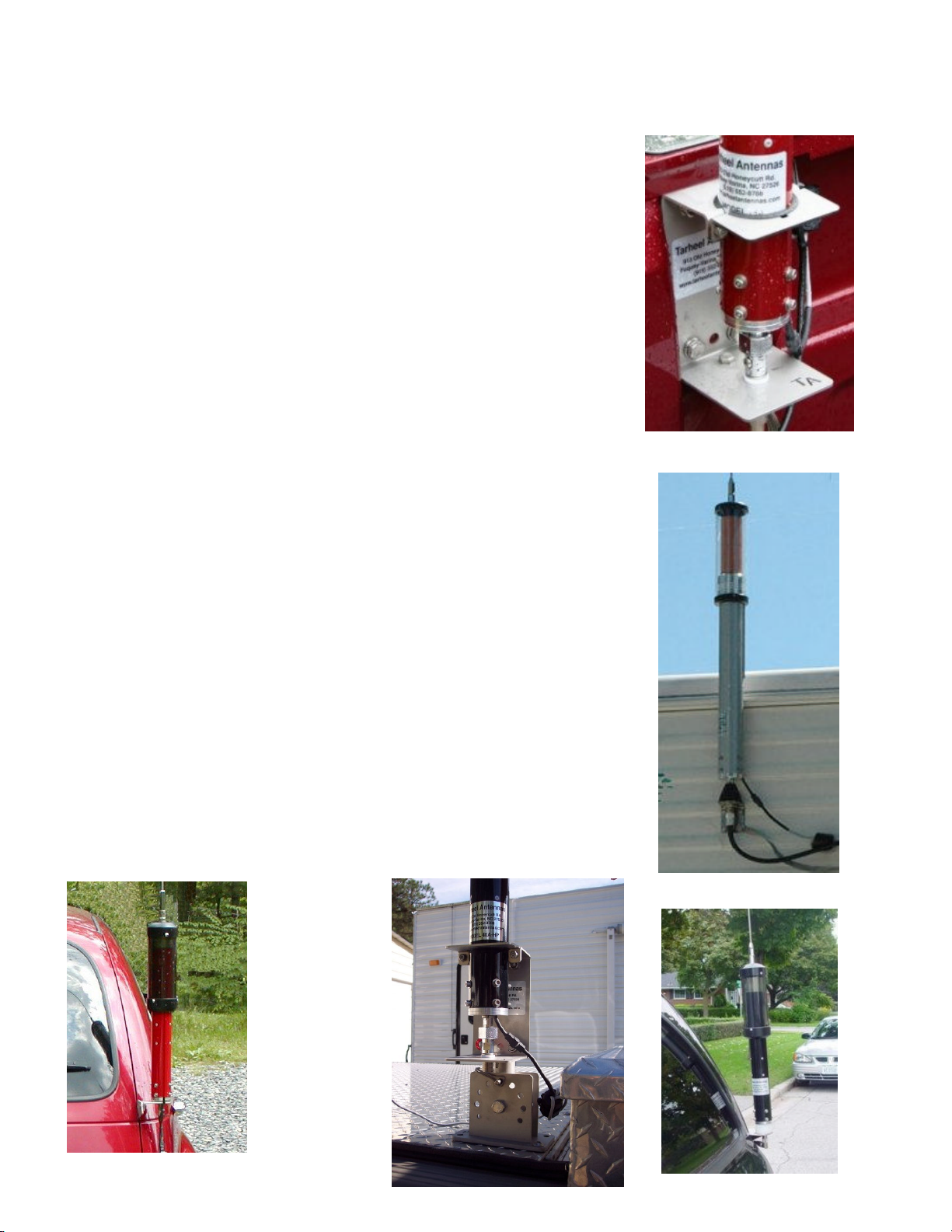
Picture 1 -- Small MT-1
Picture 2 -- Beehive Mount
Picture 5 -- SS Flat Plate
Installation
Before installation of this antenna there are a few
things you have to consider. To get peak performance you
need to try to mount the antenna in a location where
the decoupler (this is where the coil comes out of the
antenna) is at least as high as the highest part of the
vehicle. Next, and this is the most important is the
vehicle ground plane must be close (12" or less) to the
base of the antenna, this ground can be provided with
ground strap at least 1" wide (small wire does not carry the
RF ground well). The best way to provide this RE ground is
to use mounts that are bolted directly to the vehicle
ground that are unpainted or uncoated to provide the
best RF and DC ground path for the antenna. All
mounts made by Tarheel Antennas are glass beaded 304
stainless steel. In most cases with these mounts no other
grounding is required. Some examples are in pictures 1- 5.
After installation if the SWR will not go below 1.5 on
the frequencies above 10 MHz it's because of the
ground path mentioned above. Again, ground close to the
base is most important with this and any other
antenna.
This is a large antenna that will require heavy duty
mounts to withstand the pressure produced from the
windload. All of the Tarheel Antenna mounts are
designed to take this load.
While we have a variety of mounts to lay the antenna
down horizontally, it's designed to be mounted
vertically. While using these mounts, just make sure the
anti-rotation rib that's on the antenna will be at the bottom
while in the horizontal position.
Picture 3
--
SS Door Jam Mount
Picture 4
---
MT11S & Small MT
-
1

Picture 6
Picture 8
Pict
ure 7
The MT-1 antenna bracket is designed to make your antenna
mounting convenient and incredibly strong. Made to clamp to
standard 1" pipe (1.312 OD) or bolted to a flat surface. (Picture 6)
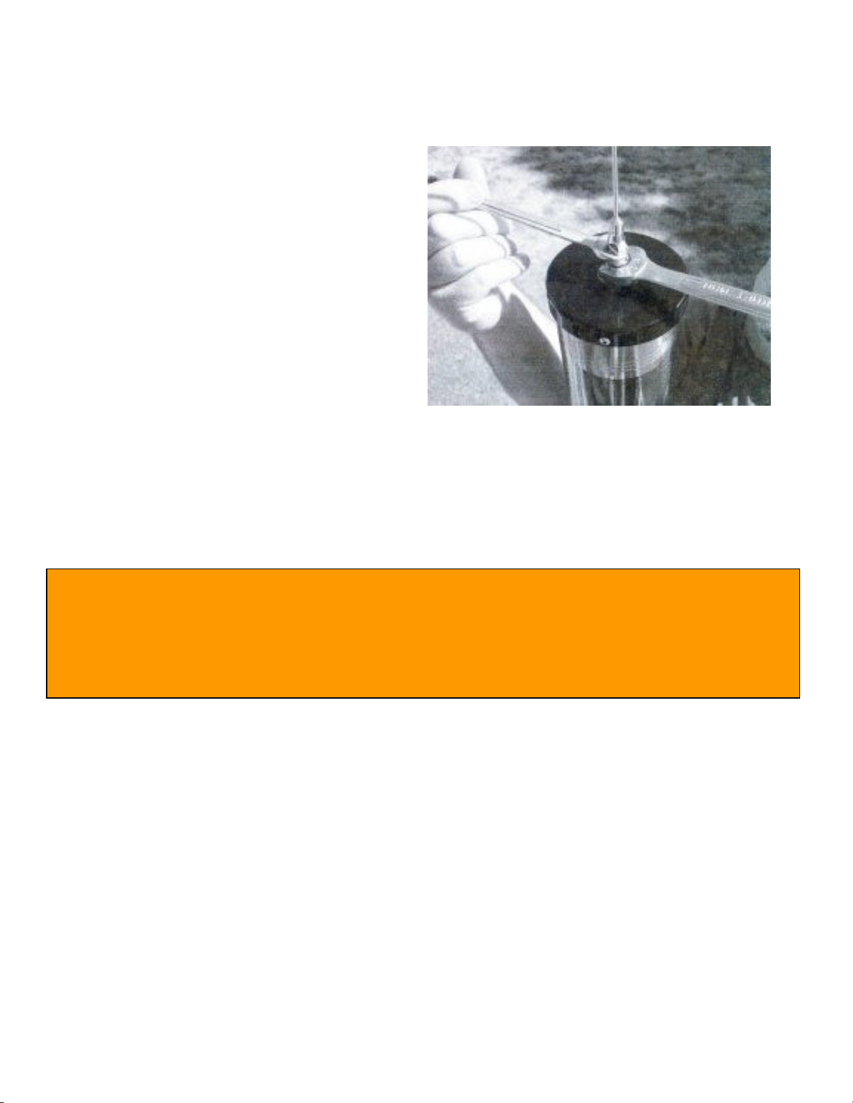
There are a few steps to make
sure you install the MT-1
antenna bracket the way it
was intended. First you need
to install the upper half of the quick disconnect
in the bottom of the antenna tight (Picture 7). Be
sure to use the lockwasher
The MT-1_ antenna bracket has 6 cutouts for the anti-
rotation rib that's on the antenna. Be sure the rib
goes into one of these cutouts, there is no need
to cut the insulator, it will compress enough to
tighten the antenna down. (Picture 8)
Don't forget to tighten
down the top half
plate and the quick
disconnect.
(Pictures 9 & 10)
Picture 9 Picture 10

Picture 13 Picture 12
Included with the antenna is a special mix
#31 ferrite core that needs to be
mounted on the control cable as close to
the antenna as possible. Loop the cable
through the ferrite core a minimum
of 3 time s. (Picture 11) It is used to
decouple the control cable from the
antenna. If you fail to install this ferrite
core the control cable acts like a single
radial and the antenna will be untunable.
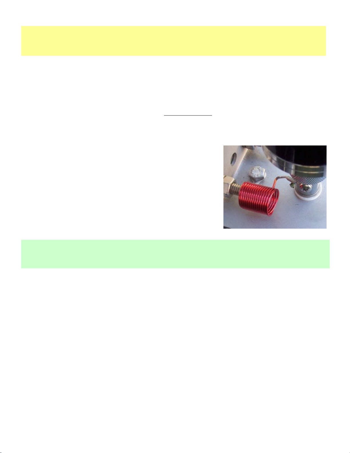
The next thing is the matching coil. This coil must
go from the antenna base to the immediate ground.
The Small MT-1 antenna bracket provides this
connection. On a loaded mobile antenna below
10 MHz some form of impedance matching is
required. Pictured is the matching coil on Small
MT-1 bracket (Picture 12).
The up/down switch (Picture 13) that comes
with the antenna package will plug directly
into the control cable to the antenna, then
there will be 2 wires left on the switch. One
will be white with red dots and one red with
black dots. This system is designed for a
sta n d a r d 1 2 vdc sy stem. Ke e p i n m i n d
polarity of these two wires are not important.
This switch just reverses polarity for motor
movement. With the switch mounted up
(wire on bottom) you can wire the red wire
with black stripes to positive side of your 12vdc system, and the white wire with
red stripes to the negative side. This will allow the antenna to go up while you press
the up button (this is the way most wire up their systems). Up on switch means
the antenna is going UP in height and DOWN in frequency. If you prefer that reversed
all you have to do is reverse the connections. Be sure you add the fuse to the positive
side.
Most installs: Red with black dots -- 12 volt positive
White with red dots 12 volt ground
Do not try to twist or turn the bug shield on the
outside of the antenna, this is designed not to
turn.
Now You Need To Install The Top Whip
Whip Length versus Frequency Coverage
32 in. -- 9.0 MHz to 58.0 MHz
4 ft. --8.0 MHz to 49.0 MHz
5 ft. - 7.0 MHz to 37.0 MHz
6 ft. - 6.5 MHz to 32.0 MHz
8 ft. 5.5 MHz to 23.0 MHz
10 ft. - 5.0 MHz to 21.0 MHz
12 ft. -- 4.5 MHz to 19.0 MHz
CH-1- Capacitance Hat
Hat only -- 7.0 MHz to 45.0 MHz
Hat with 3 ft. whip 6.5 MHz to 27.0 MHz
Hat with 6 ft. whip -- 5.3 MHz to 25.0 MHz
Our standard whip is 6 ft. long; it can be cut to any length for the coverage you need.
Keep in mind that the longer your whip is the better the performance will be on the
lower bands, however you will loose your upper frequencies with the longer whip. As
an example, if your main frequencies are 15 meters thru 60 meters then the
capacitance hat plus the 6 ft. whip are a powerful combination.
Initial Tune Up
For the initial tune up a SWR analyzer is nice to have if you have access to one. If not,
make all your adjustments with low power. Now, lower your antenna until it reaches
the end stop and go to 10 meters (or your highest frequency depending on whip
length) and check your SWR, it should be low. Next, you can go to 15 meters and raise
the antenna until you get a SWR dip there. Then 20, then so on.
Keep in mind that 10-20 meters are close together. If the SWR doesn't go below
1.5 on these bands the ground is probably too far away, remember the ground
needs to be less than 1 foot from the base of the antenna.
Now you need to go to the middle of 20 meters and check your SWR. Record that and
then go to 40 meters and do the same. Your standing wave should be below 1.5 on
both bands. If it is below 1.5 on both bands no adjusting is needed on the matching coil.
However, if the SWR is above 1.5 on 20 meters and low on 40 meters this means
there is too much inductance from the matching coil. This can easily be corrected
by simply spreading the matching coil (Example 7) a very small amount until a low
SWR is attained on 20 and 40 meters. If you have spread the coil approximately 1 1/2
inches wide and the SWR has not dropped on 20 meters then there is most likely a
ground issue.
However, keep in mind if you had to go to this extreme
to tune, your ground path is most likely too far away or
you have other antennas too close to this antenna.
If properly installed this antenna will have a standing
wave b e lo w 1 .5 from 7.0 t o 3 0 MHz (cov erage
depends on whip length. We know that every antenna
installation is unique and it is impossible to describe
all the scenarios in this manual. However, if you are
having problems with this initial tuning please call.
With everything working and your ready to button this system up, then you need to
put a small dab of dielectric compound or petroleum jelly (Vaseline) in the molex
connector at the antenna and also in the PL259 at the antenna. Wipe off any
excess and then seal the molex plug and coax connector with Coax Seal or tape.
We've seen this technique used for years on installs in the northern states where a
lot of salt is used on the roads in the wintertime and when disassembled they
look as clean and shiny as the day they were installed.
Operation
Remember that when the coil is all the way in it's resonant on the high bands and
all the way out on the low bands. It will take a little time to get use to this style of
antenna, some mark the antenna with tape to mark the approximate location of
the bands, some just listen to the noise level increase on the radio's receive when
it's close to resonant. When you fine tune you need to transmit a low carrier (AM,
FM, CW) at 5 to 10 watts and watch the SWR meter until the dip. There are also
several types of controllers on the market; most are good in their on unique way.
NOTE: Don’t use the Dielectric Compound or Coax Seal until
all testing has been done.
IMPORTANT: Don't make any adjustment to the matching
coil until you read and understand the next paragraph.
Example 7
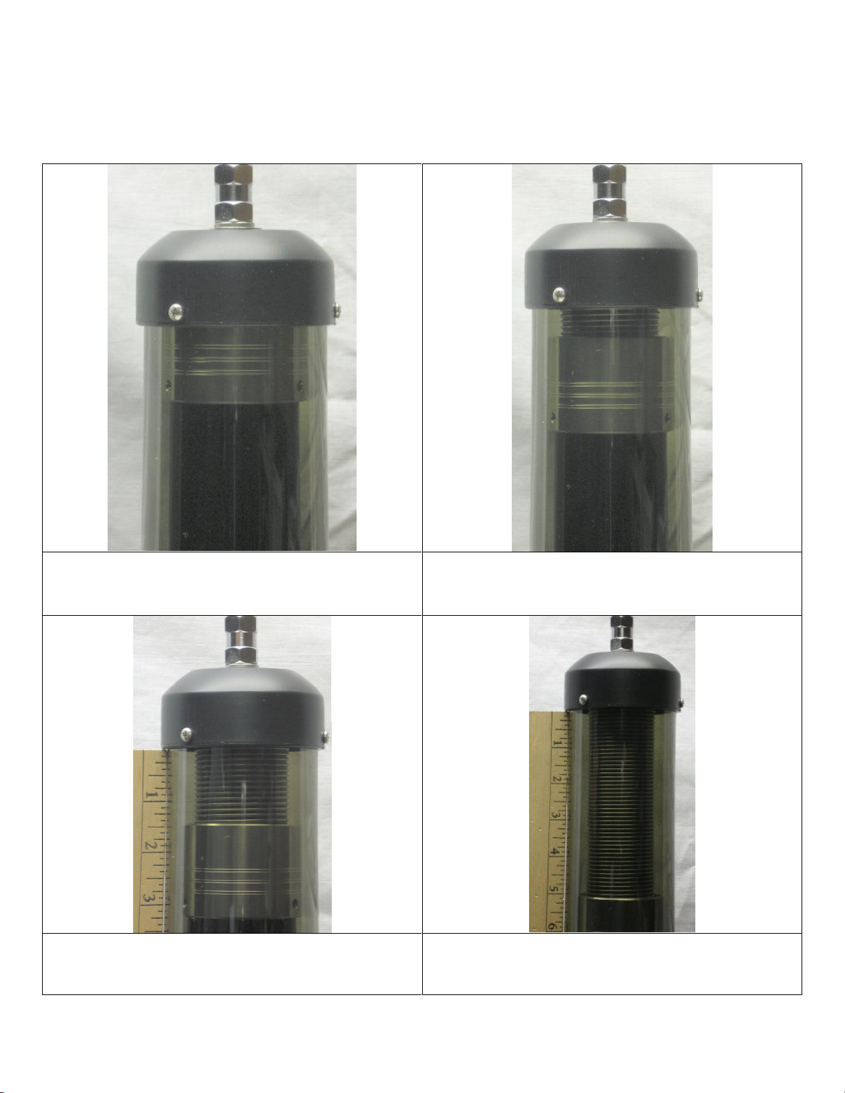
Relative Tuning Positions
The following photos will show you relative tuning positions of the Model 40A-HP Tarheel
Antenna.
Model 40A-HP -- full down position with
5 ft. whip -- 37.0 MHz
Model 40A-HP -- 28.0 MHz with
5 ft. whip @1/2" of coil showing
Model 40A-HP -- 14.2 MHz with
5 ft. whip @ 1/2" of coil showing
Model 40A-HP -- 7.1 MHz with
5 ft. whip @ 5" of coil showing

Maintenance
Very little maintenance is required for your Tarheel Antenna. You should have
years of trouble free service from this antenna. You've made a large investment
for a mobile antenna. Here is a tip to help take care of your investment.
About once per year or so, depending on how much driving you do and where the
antenna is mounted you will need to wash the coil to remove any road grime, no
parts to replace. Also a dirty coil will show vertical black streaks. Here's how:
1. Run the antenna up till all the coil is exposed.
2. There are 3 screws in the top Delrin Cap, you'll remove them then slide the Lexan
down to expose the coil, next feel the coil, is it sticky? If so it's dirty, now wipe
the coil with alcohol, then scrub the coil with a Scotch-Brite pad (available at any
hardware store), then one more wipe with alcohol and that's it.
3. Now slide the Lexan back in the cap, don't even try to align the screw holes, it's best
to redrill (7/64" drill bit) the Lexan using the cap holes as guides and let the screws
make new threads.
4. After you have the antenna reassembled, now is the time for a good cleaning
on the outside. Use the alcohol to remove the grime off the tube and Lexan, next
get a good coat or two of wax on it.
Warranty & Guarantee
The antenna comes with a one year guarantee for quality and workmanship. If for any
reason (other than damage due to negligence, improper use or unauthorized
disassembly) your Tarheel Antenna fails to perform due to quality or workmanship
Tarheel Antennas will at our discretion either repair or replace at no charge for parts
and/or labor. A return authorization number is required before warranty work can be
performed. Your antenna needs to be sent in to the manufacturer for any warranty
repairs. All shipping charges are your (the customer's) responsibility to and from Tarheel
Antennas, Inc.
If for any reason the antenna does not meet the advertised specifications or any other
reason you are dissatisfied with the antenna in the first 30 days of receipt of the antenna
you may return it for a full refund minus any shipping charges incurred. You must inform
Tarheel Antennas, Inc. of your intention to return the antenna prior to shipping. Once
Tarheel Antennas, Inc. receives your antenna a refund will be processed within 30 days,
only after it has been determined that the antenna has not been altered, mishandled,
disassembled or damaged in any way.
Please understand, we will not under any circumstances send out warranty parts, no
matter how good of an engineer you are. If your antenna is still under warranty and you
insist on doing the repairs yourself, we will be more than happy to sell you the parts.
Please pass along any suggestions you may have to make our company and antennas
better. All suggestions are appreciated.
Thanks,
Tarheel Antennas
Table of contents
Other Tarheel Antennas Antenna manuals

Tarheel Antennas
Tarheel Antennas MFJ-1792 User manual

Tarheel Antennas
Tarheel Antennas Little Tarheel HP User manual

Tarheel Antennas
Tarheel Antennas Little Tarheel II User manual

Tarheel Antennas
Tarheel Antennas 400A User manual

Tarheel Antennas
Tarheel Antennas Little Tarheel II User manual

Tarheel Antennas
Tarheel Antennas 300A User manual

Tarheel Antennas
Tarheel Antennas 100A-HP User manual

Tarheel Antennas
Tarheel Antennas Stubby 75A User manual

Tarheel Antennas
Tarheel Antennas 200A-HP User manual


