CSS Technologies 3010 User manual

AM Floor Antenna System
Model-3010/3011/2000
Installation Manual
Beijing CSS Technologies Development Co., Ltd.
http://www.csstech.com.cn
Copyright © 2011, CSS Technologies. All rights reserved.
RD20111110 R1.0
CSS

Table of Contents
System Overview.............................................................................................1
Important Safety Precautions................................................................................................... 1
Components ....................................................................................................2
Capacitor Box..................................................................................................3
Rear View................................................................................................................................. 3
Front View................................................................................................................................ 3
Layout and Installation of Antennas..............................................................4
Preparation of Installation ........................................................................................................ 5
Positioning and Fixing Antennas.............................................................................................. 5
Connection of System.............................................................................................................. 5
Capacitance Matching.............................................................................................................. 7
Possible Failure........................................................................................................................ 8
Environmental requirements..........................................................................8
CSS AM Floor System Specifications ...........................................................9
CSS

1
System Overview
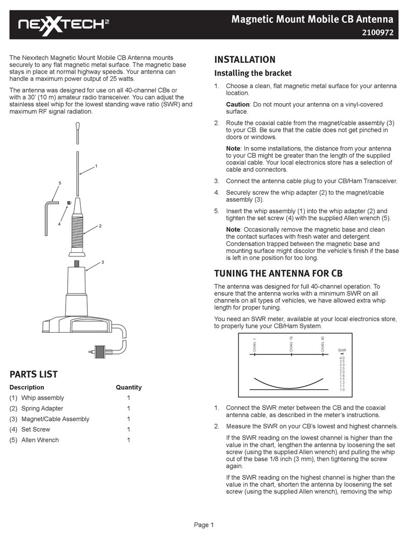
Floor antenna system consists of three parts: Antenna, Controller and Capacitor Box
Important Safety Precautions
WARNING
The electronics inside the controller and the antenna is
extremely sensitive to static electricity. Always
discharge yourself by touching ground point before
touching any of the electronics to avoid damage.
WARNING
Electronics are with high voltage, when opening the
housing of the controller or the antenna base cover, do
not touch with your hands the solder points, the antenna
PCB radiator or any other non isolated places.
PRECAUTION
All AMS devices should be powered from the mains supplied
by power plant. The use of power generated by standby
power generator may result in fail in synchronization of
different systems. The outlet must have good grounding.
PRECAUTION
The line supplying power to the box must not be shared with
other electronic or electrical loads, such as electronic
transformers, neon lights, electrical engines, computers,
LCD screens and cash registers, etc.
PRECAUTION
Avoid disconnecting any antenna closing to the operating
antennas. Otherwise, the disconnected antenna will become
a 58KHz RX loop resonant circuit and interfere with the
closing operating antennas (generating serious interfering
noise). Therefore, all RX- and RX+ cables (in and out leads
of the receiver coils) of the disconnected antennas must be
short-circuited, either at the antenna or at the corresponding
controller connector side (shown as picture below).
CSS

2
Components
AMA2000
Antenna
Alarm buzzer is not together with the antenna. The buzzer is connected directly connected to controller.
AMS3010 Capacitor
Box
AMS3011
Controller
Power Cable of Controller RS485 RX&TX Cables
Cables
CSS

3
Capacitor Box
Rear View
1) RX1 IN: Connect to antenna receiver
2) TX1 IN: Connect to antenna transmitter
Up to three antennas can be connected to one capacitor box: RX1/TX1, RX2/TX2, RX3/TX3
Front View
1) RX1 OUT: Connection to controller receiver
2) TX1 OUT: Connection to controller transmitter
NOTE
For other important information of the electronics in the
capacitor box see
<AM_EAS_System_TechnicalManual_eng_R2.0 > Page 7
CSS

4
Layout and Installation of Antennas
Up to three antennas can be connected to one controller and one capacitor box.
Please decide number of antennas to be installed according to the specific test range of the floor
antenna.
Label Hard Tag
Detection
height (m)
Detection
Width (m)
Detection
height (m)
Detection
Width (m)
Antennas 0.6-0.9 2.0-2.2 1.2-1.6 2.0-2.2
Note:
1. Strongly suggest to install antennas one by one without leaving gap between each other
in order to guarantee the best performance;
2. The actual detection height will be seriously interfered by the influence of metal parts
under the floor and the length of cable kit from the controller to the antenna.
2.0-2.2m
CSS

5
Preparation of Installation
Always check the installation site of the end-user before signing any agreement with customer and before final
installation. If the antenna has to be very close to big metal frame or big metal part underground, you have to
inform the customer that the detection performance of the floor antenna system will be interfered seriously by
the metal object and the detection height might not be as high as they expect. Never guarantee to customer the
final performance of the floor system except that you have chance to make a real test on site of installation
before reaching agreement or starting installation. No AM EAS supplier in the world can guarantee the final
performance of floor antenna system before on-site investigation.
Positioning and Fixing Antennas
1. Make sure level of the antenna into the prepared groove on the ground.
2. Leave the antenna cable outside of the floor after the floor is completely covered.
Note:
The system should maintain a certain distance with large metal objects and other electrical devices.
Otherwise the large metal objects might cause serious interference to the system.
Connection of System
1. Connect Antennas and Capacitor Box
The antenna plug is connected to the front panel of the capacitor box shown as below:
Note:
The distance between the antenna and the capacitor box should be as short as possible in order to
prevent serious signal attenuation. The distance must not be more than 8 meters.
2. Connect the Controller and Capacitor Box
Insert the RX cable connector into the【RX OUT】interface on the capacitor box. Similarly insert the
CSS

6
TX cable connector into the 【TX OUT】interface on the capacitor box.
And connect the other end of the cable with the controller.
Note:
Try to place the capacitor box together with the controller. Better to use a standard 0.5m cable between the
controller and the capacitor box.
3. Connect the External Alarm Buzzer and the Controller
If you need an alarm buzzer. Connect an external alarm buzzer connector to the controller shown
as below:
4. The connection of the whole system is completed
CSS

7
Capacitance Matching
Transmitting current is observed by an oscilloscope which shall be between 15A to 20A. If the
transmitting current was too small, the system would not work properly.
1. Clamping an oscilloscope current probe onto the transmitter red (positive) wires (a pair) connecting
to the capacitor box.
2. Switch on the oscilloscope current probe, then power on the controller. If the transmitting current is
15A or higher (better to be higher), it means that the floor antenna system can work normally.
Otherwise, you have to make capacitance matching by adding capacitors on the PCB inside the
capacitor box. The lower the transmitting current is, the higher the value of capacitor added shall be.
Shown as below.
3. Power off. Disconnect the controller from power source. Open the capacitor box. Take the PCB out
from the controller. Pay attention to the wires connected. (Shown as below)
4. Find the corresponding position on the PCB for soldering the capacitor. Normally, the new capacitor
shall be added at C26 or C27 position. Since the space for capacitor might be limited on the front
side of the PCB, you might need to solder capacitor on back side of the PCB. In that case, please
make sure you find the right position before soldering.
CSS

8
5. Nobody knows what value of capacitor(s) shall be added. Just try with different capacitors until get
the right one(s). Normally, the added capacitor shall be from 2nF to 5nF.
6. When the transmitting current reach or close to 15A, you can start to adjust the positions of jumpers
on J1 to J8.
J1~J8 Description
OFF. Meaning the capacitor is disconnected and the total
capacitance of the board will be decreased.
ON. Meaning the capacitor is connected and the total
capacitance of the board will be increased.
Note:
(1) J1 to J8 capacitors are just for fine tuning only;
(2) The values of J1 to J8 are from the highest to the lowest;
(3) Any of J1 to J8 jumpers can be on any position – ON or OFF.
7. The result of the best capacitance matching shall be that the transmitting current will be always
decreasing once you put any of jumpers (J1 to J8) on positions ON (if it is on OFF position originally)
or OFF (if it is on ON position originally)
8. Assemble the board(s) into the capacitor box and fix the cover of box. The capacitance matching
work is completed.
Possible Failure
There is always possible failure in capacitance matching work (the transmitting current can never
reaching 15A) if the floor antenna is too closed to large metal objects under the ground. In this case, the
detection performance of the floor antenna system will not be good enough and you have to tell your
customer directly.
Please kindly note that we, Beijing CSS Technologies Development Co., Ltd., do not promise to any
partners or customers about the performance of our floor antenna systems. So, you should not promise
to your customers as well before on-site investigation and test.
Environmental requirements
1. Keep the controller and the capacitor box on dry and clean place with good ventilation.
2. Always power on after confirming good connection of all cables, wires and connectors. All
connections DO NOT support hot plug in and off.
3. Prevent water from entering into the controller and the capacitor box.
NOTE Other important information example software setting , etc.
<AM_EAS_System_TechnicalManual_eng_R2.0 >
CSS

9
CSS AM Floor System Specifications
Electrical
AMS-3010 Controller
Primary Input.................................... 110/220VAC,50-60Hz
Primary Power Fuse...........................3.15/5.0A
Current Draw.................................... 5.0A@120VAC, 3.15A@230VAC
Input Power..................................... 450W@120VAC with3 ants
450W@230VAC with 3 ants
Operating Frequency..........................50-60Hz
Transmit Burst Duration......................1.6ms
Transmit Current............................... 8 – 16Ao-p
Center Frequency.............................. 58kHz±200Hz
Cap Board Tx/Rx cable.......................8m Max.
Cap Board Comm. cable.....................0.5m Standard
Environmental
Operating Temperature...................... 0°C ~50℃
Relative Humidity.............................. 0%~90%RH, Non-condensing
Mechanical
AMS3010 controller
Length............................................. 425mm
Width.............................................. 198mm
Depth.............................................. 122mm
Net Weight....................................... 5.5Kg
AMS3011 Capacitor Box
Length............................................. 307mm
Width............................................... 207mm
Depth.............................................. 192mm
Net Weight....................................... 4.8Kg
AMA-2000 Antenna
Length............................................. 1650mm
Width............................................... 650mm
Depth.............................................. 36mm
Net Weight....................................... 24Kg
CSS
This manual suits for next models
2
Table of contents
Popular Antenna manuals by other brands

Diamond Antenna
Diamond Antenna SG-M510 Assembly
Altelix
Altelix AY9G M2-PRO Series Assembly instructions
OmniMetrix
OmniMetrix TrueGuard-PRO Basler DGC2020 installation guide

Sennheiser
Sennheiser AC 3 instruction manual

RADIOHAUS
RADIOHAUS SPIDERDXMAN RH-DX1020 Assembly instructions
COBHAM
COBHAM Saailor Fleet One installation guide

