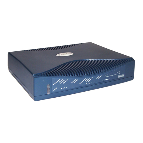
Tasman 1200 Series User manual

TiOS version 8.0
July 2004
Installation
Guide:
1200-1400-6200-7000
Series Routers

http://www.tasmannetworks.com
July 2004
111-00145-01
8.0
Tasman Networks, Inc. 525 Race Street, Suite 100 San Jose, California 95126 USA
1-408-216-4700
Copyright
Copyright © Tasman Networks, Inc., 2003. All rights reserved. No part of this documentation may be reproduced in any form or by any means
without prior written authorization of Tasman Networks.
Tasman Networks reserves the right to revise this documentation and to make changes in content from time to time without obligation to
provide notification of such changes.
Tasman Networks provides this documentation without warranty, express, implied, statutory, or otherwise, and specifically disclaims any
warranty of merchantability, or fitness for a particular purpose. Tasman Networks may make improvements or changes in the product(s) and/or
the program(s) described in this documentation at any time.
Trademarks
Tasman Networks and the Tasman corporate logo are trademarks of Tasman Networks, Inc. All other trademarks appearing in this guide are the
exclusive property of their respective owners.
Software Notice
Tasman Networks, Inc. assumes no responsibility for product reliability, performance, or both if the user modifies the .CFG file. Full
responsibility for any performance issues resulting from modifications made to the .CFG file, by the user, is assumed by the user.
Hardware Notice
The Lithium battery in this product is part of a non-volatile memory device and will retain data for 10 years in the absence of power. Tasman
Networks does not consider the lithium battery in this unit a field replaceable or serviceable part and should not be accessed by the customer.
WARNING: Before working on this equipment be aware of good safety practices and the hazards involved with electrical circuits.
CAUTION: To reduce the risk of fire, use only number 26 AWG or larger UL Listed or CSA Certified Telecommunication Line Cord
for all network connections.
CAUTION: Risk of explosion if battery is replaced by an incorrect type. Dispose of used batteries according to the instructions.
Documentation Feedback
The mission of the Technical Publications group at Tasman Networks is to provide quality documentation that enhances the user’s experience
with Tasman products. We are constantly improving our guides and have a genuine interest in ensuring that they are easy to use and enable you
to quickly find information you need. We invite you to be part of this process; please email your comments regarding Tasman Networks product
documentation and web content to:
feedback@Tasmannetworks.com

Installation Guide: 1200-7000 Series Routers
TiOS version 8.0
T
ABLE OF
C
ONTENTS
Copyright ....................................................................................................................................2
Trademarks..................................................................................................................................2
Software Notice...........................................................................................................................2
Hardware Notice .........................................................................................................................2
Documentation Feedback............................................................................................................2
1 ABOUT THIS GUIDE
Organization................................................................................................................................12
Conventions ................................................................................................................................13
Notices ....................................................................................................................................13
Documentation............................................................................................................................14
Related Tasman Guides ..........................................................................................................14
2 PRODUCT INTRODUCTION
1200 and 1400 Series..................................................................................................................15
Tasman 1200...........................................................................................................................15
Tasman 1200E.........................................................................................................................16
Tasman 1400...........................................................................................................................17
Tasman 1400E.........................................................................................................................18
Tasman 1450...........................................................................................................................19
Tasman 1450E.........................................................................................................................20
Dial-Out Port...........................................................................................................................20
Back-Panel Components.........................................................................................................21
4000 Series Systems....................................................................................................................22
Tasman 4100...........................................................................................................................22
Tasman 4102...........................................................................................................................23
Back-Panel Components.........................................................................................................24
6000 Series Systems....................................................................................................................25
Tasman 6200...........................................................................................................................25
Tasman 6200E.........................................................................................................................26
Tasman 6300...........................................................................................................................27
Tasman 6302...........................................................................................................................28
Back-Panel Components.........................................................................................................29
7000 Series Systems....................................................................................................................30
Tasman 7030...........................................................................................................................30
Back-Panel Components.........................................................................................................31
3 INSTALLATION
Site Preparation...........................................................................................................................34
Environment............................................................................................................................34
Site Safety...............................................................................................................................34
Power Requirements...............................................................................................................35
Network Connection ...............................................................................................................35

Installation Guide: 1200-7000 Series Routers
TiOS version 8.0
Equipment Rack......................................................................................................................35
Tools and Materials.................................................................................................................36
Cables..................................................................................................................................36
Tools....................................................................................................................................36
Materials..............................................................................................................................36
Unpacking the System.................................................................................................................37
Mounting the System ..................................................................................................................38
Surface Mount.........................................................................................................................38
Rack Mount.............................................................................................................................38
Important information for the 6200 system.........................................................................38
System Power..............................................................................................................................40
DC Power................................................................................................................................40
AC Power................................................................................................................................41
Single AC Power.................................................................................................................41
Dual AC Power ...................................................................................................................41
External Alarms...........................................................................................................................43
Connecting to the Network .........................................................................................................44
LAN Interface .........................................................................................................................44
T1 WAN Interface...................................................................................................................44
CT3 WAN Interface................................................................................................................45
Clear Channel T3 WAN Interface...........................................................................................45
USSI Interface.........................................................................................................................46
HSSI Interface.....................................................................................................................46
V.35 Interface ......................................................................................................................47
Operator Interface .......................................................................................................................48
Local Access ...........................................................................................................................48
Remote Access........................................................................................................................48
Telnet.......................................................................................................................................49
Console Messages...................................................................................................................49
Connecting a Modem ..............................................................................................................50
Hayes Compatible Modem Configuration ..........................................................................51
4 CONFIGURATION
Applying Power...........................................................................................................................53
Logging In...................................................................................................................................54
Command Tips........................................................................................................................54
Configuration Tips ..................................................................................................................55
HSSI and V.35 Interface......................................................................................................55
Ethernet ...............................................................................................................................55
Changing Login Parameters........................................................................................................56
Password..................................................................................................................................56
Administrator Account............................................................................................................56
System Host Name..................................................................................................................56
Date and Time .........................................................................................................................57
Adding Users...........................................................................................................................58
Removing Users......................................................................................................................58
Default Configuration .................................................................................................................59
USSI Interface.............................................................................................................................61
Boot Process................................................................................................................................62
IC Recovery.............................................................................................................................63
Upgrading System Software........................................................................................................64
Before Downloading the NCM File........................................................................................64
Booting From a Local TFTP Server........................................................................................64
Limited Upgrade .....................................................................................................................67
Full Upgrade............................................................................................................................68
Interface Configuration ...............................................................................................................70
Bundle Configuration..................................................................................................................73

Installation Guide: 1200-7000 Series Routers
TiOS version 8.0
Routing Configuration ................................................................................................................79
Saving Configurations.................................................................................................................82
5 TROUBLESHOOTING
Alarms and System Status...........................................................................................................83
WAN Statistics........................................................................................................................85
Network Tests .............................................................................................................................86
Ping Test .................................................................................................................................86
T1 Tests...................................................................................................................................86
Loopback Test.....................................................................................................................86
BERT Test...........................................................................................................................86
Serial Port Tests......................................................................................................................87
Monitor Port............................................................................................................................87
Diagnostics Tips..........................................................................................................................88
General Symptoms..................................................................................................................88
HSSI........................................................................................................................................91
V.35.........................................................................................................................................92
A SPECIFICATIONS
Environment and Power..............................................................................................................94
Interface ......................................................................................................................................95
Cable Pinouts ..............................................................................................................................98
MIBs............................................................................................................................................104
BLED STATES
C MAINTENANCE
AC Fuse.......................................................................................................................................113
Servicing the Cooling System.....................................................................................................115
Fan Filter.................................................................................................................................115
Replacing Filters .................................................................................................................115
Fans.........................................................................................................................................116
D ACCESSORIES
Accessories..................................................................................................................................119
E COMPLIANCE AND STANDARDS
Compliance .................................................................................................................................121
FCC Conformance ......................................................................................................................122
FCC Part 15.............................................................................................................................122
FCC Part 68.............................................................................................................................122
Incidence of Harm...................................................................................................................123
Rights of the Telephone Company..........................................................................................123
Industry Canada ..........................................................................................................................124
VCCI Class A ITE ......................................................................................................................125
INDEX
CORPORATE POLICY
Standard Warranty ......................................................................................................................131
Hardware.................................................................................................................................131
Software..................................................................................................................................131

Installation Guide: 1200-7000 Series Routers
TiOS version 8.0
Technical Support ...................................................................................................................131
Procedures ...............................................................................................................................131
Exclusions ...............................................................................................................................131
Non-Tasman Networks Products ............................................................................................131
Disclaimer of Warranty...........................................................................................................131
Limitation of Liability.............................................................................................................132
Equipment Malfunction...............................................................................................................132
Contacting Tasman Networks.....................................................................................................132

Installation Guide: 1200-7000 Series Routers
TiOS version 8.0
F
IGURES
11200 System Front Panel ............................................................................................15
21200E System Front Panel..........................................................................................16
31400 System Front Panel ............................................................................................17
41400E System Front Panel..........................................................................................18
51450 System Front Panel ............................................................................................19
61450E System Front Panel..........................................................................................20
71000 Series System Back Panel .................................................................................21
84100 System Front Panel ............................................................................................22
94102 System Front Panel ............................................................................................23
10 4000 Series System Back Panel .................................................................................24
11 6200 System Front Panel ............................................................................................25
12 6200E System Front Panel..........................................................................................26
13 6300 System Front Panel ............................................................................................27
14 6302 System Front Panel ............................................................................................28
15 6000 Series System Back Panel..................................................................................29
16 7030 System Front Panel ...........................................................................................30
17 7000 Series System Back Panel..................................................................................31
18 Chassis Air Flow.........................................................................................................34
19 Attaching Mounting Brackets.....................................................................................39
20 Rackmounting the System ..........................................................................................39
21 DC Power Terminal Block Connections.....................................................................40
22 Connecting the AC Power Cord..................................................................................41
23 Preparing Alarm, DC Power, and Ground Wires........................................................43
24 System Alarm Connections.........................................................................................43
25 Connecting the LAN Cable ........................................................................................44
26 Connecting T1 WAN Cables .....................................................................................45
27 Connecting Channelized T3 WAN Cables ................................................................45
28 Connecting Clear Channel T3 WAN Cables .............................................................46
29 Connecting the HSSI Cable ........................................................................................46
30 Connecting the V.35 Cable.........................................................................................47
31 Connecting a Local Console .......................................................................................48
32 Remotely Accessing a Tasman System ......................................................................49
33 Connecting a Modem..................................................................................................50
34 Boot Process Flow Chart.............................................................................................62
35 Back Panel: AC Fuse Location...................................................................................113
36 AC Fuse Access ..........................................................................................................113
37 Access to Fan Assembly .............................................................................................115
38 Replacing a Fan Unit...................................................................................................116


Installation Guide: 1200-7000 Series Routers
TiOS version 8.0
T
ABLES
1Guide Organization: Chapters.....................................................................................12
2Guide Organization: Appendices................................................................................12
3Text Conventions........................................................................................................13
41200 System Front-Panel Connectors.........................................................................15
51200E System Front-Panel Connectors ......................................................................16
61400 System Front-Panel Connectors.........................................................................17
71400E System Front-Panel Connectors ......................................................................18
81450 System Front-Panel Connectors.........................................................................19
91450E System Front-Panel Connectors ......................................................................20
10 1000 Series System Back-Panel Components ............................................................21
11 4100 System Front-Panel Connectors.........................................................................22
12 4102 System Front-Panel Connectors.........................................................................23
13 4000 Series System Back-Panel Components ............................................................24
14 6200 System Front-Panel Connectors.........................................................................25
15 6200E System Front-Panel Connectors ......................................................................26
16 6300 System Front-Panel Connectors.........................................................................27
17 6302 System Front-Panel connectors..........................................................................28
18 6000 Series System Back-Panel Components ............................................................29
19 7030 System Front-Panel Connectors.........................................................................30
20 7000 Series Systems Back-Panel Components...........................................................31
21 Empty Vertical Space Requirement............................................................................38
22 DB-25 to DB-9 Pinout ................................................................................................50
23 Generic Hayes Modem Commands ............................................................................51
24 Ethernet Interface Default Configuration ...................................................................59
25 IP Default Configuration.............................................................................................59
26 CT3 Interface Default Configuration..........................................................................59
27 DS3/T3 Interface Default Configuration ....................................................................60
28 T1 Interface Default Configuration.............................................................................60
29 HSSI Interface Default Configuration........................................................................60
30 V.35 Interface Default Configuration.........................................................................60
31 Upgradable IC Cards...................................................................................................68
32 BERT Test Patterns.....................................................................................................87
33 Common Symptoms and Actions ...............................................................................88
34 HSSI Symptoms and Actions......................................................................................91
35 V.35 Symptoms and Actions ......................................................................................92
36 Specifications: Environment.......................................................................................94
37 Specifications: Power..................................................................................................94
38 Specifications: Performance Monitoring ....................................................................94

39 Specifications: E1 WAN Interface..............................................................................95
40 Specifications: T1 WAN Interface..............................................................................95
41 Specifications: CT3 WAN Interface...........................................................................95
42 Specifications: HSSI Interface....................................................................................96
43 Specifications: V.35 Interface.....................................................................................96
44 Specifications: Clear Channel T3 WAN Interface......................................................96
45 Specifications: Ethernet LAN Interface......................................................................97
46 Pinouts: Tasman-to-Terminal Console Cable (DB-9).................................................98
47 Pinouts: Ethernet Cable (RJ-45)..................................................................................98
48 T1 Pinouts: Network Cable (RJ-48C).........................................................................98
49 Pinouts: E1 Network Cable (RJ-48C to RJ-48C)........................................................99
50 Pinouts: E1 Network Cable (RJ-48C to DB-15 )........................................................99
51 Pinouts: E1 Network Cable (RJ-48C to Twinax)........................................................99
52 Pinouts: E1 Network Cable (RJ-48C to BNC)............................................................99
53 Pinouts: Tasman Console to Null Modem Cable (DB-9 to DB-9) .............................100
54 Pinouts: Tasman Console to Null Modem Cable (DB-25 to DB-9) ...........................100
55 Pinouts: HSSI Connector (DTE).................................................................................100
56 Pinouts: HSSI Connector (DCE).................................................................................101
57 Pinouts: V.35 Connector (DTE)..................................................................................102
58 Pinouts: V.35 Connector (DCE)..................................................................................103
59 Standard MIBS............................................................................................................104
60 Tasman Enterprise MIBs.............................................................................................105
61 LEDs: System Status...................................................................................................107
62 LEDs: Serial Port (USSI Interface) Status..................................................................107
63 LEDs: Ethernet Status.................................................................................................109
64 LEDs: T1 WAN Status................................................................................................109
65 LEDs: Clear Channel T3 Status..................................................................................110
66 LEDs: Channelized CT3 Status...................................................................................110
67 Link Status LEDs........................................................................................................111
68 Tasman Accessories....................................................................................................119
69 T1 Regulatory and Compliance Standards..................................................................121
70 E1 Regulatory and Compliance Standards..................................................................121

Installation Guide: 1200-7000 Series Routers
TiOS version 8.0
11
1
A
BOUT
T
HIS
G
UIDE
This chapter provides information about the intended audience for this guide, how this guide is
organized, typographical conventions, the use of notices, and related documentation.
This guide is designed for network managers and technicians who are responsible for the
installation and administration of networking equipment in Telco and service provider
environments. Knowledge of Telecom technologies and standards, T1, DS3, HSSI, V.35, and
Ethernet technologies is assumed.
Instructions are provided in this guide for installing Tasman systems and configuring basic
system parameters. Procedures are also provided for tasks that can be accomplished from the
external chassis, such as fan maintenance and AC fuse replacement. Important safety instructions
related to network telecommunications equipment are included in this guide.

12
CHAPTER
1 Chapter 1: About This Guide
Installation Guide: 1200-7000 Series Routers
TiOS version 8.0
Organization The following tables describe the organization and content of this guide.
Table 1 Guide Organization: Chapters
Chapter Description
1About This Guide defines the user audience, and describes the organization of this guide, use of
special notices, and other Tasman user guides.
2Product Introduction provides a description of installation site requirements, and cables and tools
required for installing Tasman systems.
3Installation describes the system front and back panels and how to install Tasman systems.
Information is also provided about the operator interface, network cabling, alarms, and system
power.
4Configuration describes powering on the system, initial configuration, logging in, factory
defaults, and changing the default password.
5Troubleshooting provides information about network indicators, tests, and general
troubleshooting tips. A summary of common problems and solutions is also included.
Table 2 Guide Organization: Appendices
Appendix Description
ASpecifications lists the electrical, physical, and networking characteristics of Tasman systems.
Cable pinout and related MIB file information is also provided.
BLED States provides information about interpreting system LEDs.
CMaintenance provides instructions for maintaining and replacing system cooling fans, replacing
the AC fuse, and maintaining the cooling system.
DAccessories provides information about ordering cables, replacement parts, and printed
documentation for Tasman products.
ECompliance and Standards provides regulatory information and compliance information
applicable to these Tasman products.

13
Installation Guide: 1200-7000 Series Routers
TiOS version 8.0
Conventions This guide uses the following typographical conventions:
Notices Notice paragraphs alert you about issues that require your attention. The following paragraphs
describe the types of notices used in this guide.
NOTE: Notes provide tips and useful information regarding the installation and operation of Tasman
systems.
ESD: ESD notices provide information about how to avoid discharge of static electricity and subsequent
damage to Tasman systems.
CAUTION: Caution notices provide information about how to avoid possible service disruption or
damage to Tasman systems.
WARNING: Warning notices provide information about how to avoid personal injury when working
with Tasman systems.
Table 3 Text Conventions
Font Description
boldface font Used for commands that you enter, words that you type, or keyboard keys that you press.
screen font Used to display a screen capture example.

14
CHAPTER
1 Chapter 1: About This Guide
Installation Guide: 1200-7000 Series Routers
TiOS version 8.0
Documentation Tasman user guides, which are provided in portable document format (PDF), are included on the
Tasman Networks Router CD-ROM that ships with each Tasman system. The PDF files are also
available on the Tasman Networks website: www.tasmannetworks.com
To view PDF files, Adobe Acrobat® Reader® 4.0, or higher, must be installed on your workstation.
If you do not have the Adobe Acrobat Reader installed on your system, you can obtain it free from
the Adobe website: www.adobe.com.
Related Tasman GuidesIn addition to this guide, the following list includes other Tasman documentation related to these
products:
Release Notes: Printed release notes provide the latest information. If release notes are provided
with your product, follow the instructions contained within them instead of those provided in
other documentation.
Quick Start Guide: 1200-7000 Series Routers: This printed guide is designed for advanced users.
It provides a brief overview of the installation and initial configuration processes for Tasman
systems. A quick start guide is shipped with each system.
Command Reference Guide: This detailed guide provides a complete description of all Tasman
Networks command line interface (CLI) commands.
Router User Guide: This guide provides descriptions of commands available for Tasman
Networks’ implementation of BGP, OSPF, RIP, and other routing protocols.
Configuration Guide: This guide provides examples of Tasman Networks’ implementation of
BGP, OSPF, RIP, and other routing protocols.

Installation Guide: 1200-7000 Series Routers
TiOS version 8.0
15
2
P
RODUCT
I
NTRODUCTION
This chapter provides information about front and back panels for Tasman systems. In addition,
information is provided about cable connection ports and panel components.
1200 and 1400 SeriesThis section describes front- and back-panel components of the Tasman 1000 series systems.
Additional information is also provided about external cables, wiring, and connection points.
The 1000 series systems come with single AC power. Dual AC, single DC and dual DC are
available as power options.
Tasman 1200 The 1200 front panel provides connections for one monitor port, four T1 ports, two 10/100 Base-T
Ethernet ports, and one console port.
Figure 1 1200 System Front Panel
Table 4 1200 System Front-Panel Connectors
Connector Description
Monitor Port One RJ-48C connector
T1 Ports Four RJ-48C connectors
Ethernet Ports (2) One RJ-45 connector per port
Console Port DB-9 female connector
Use this port to set up a connection between a VT-100 (or equivalent) terminal (or modem)
and the 1200 system.
ESD Ground Banana plug connector
1200
Link Status Ethernet 0 Ethernet 1 Console Unit
1234
Status
Mon.
1234 Dup
HS
Link
Col
RX
TX
Power
Summary
Dup
HS
Link
Col
RX
TX
Quad T1 WAN
ESD Gnd
Monitor Port
10/100 Base-T
Ethernet Ports
Console Port
ESD
Ground
T1 Ports (4) WAN Status LED
T1 Status LEDs
LAN Status LEDs
Summary
and Power
LEDs

16
CHAPTER
2 Chapter 2: Product Introduction
Installation Guide: 1200-7000 Series Routers
TiOS version 8.0
Tasman 1200E The 1200E front panel provides connections for one monitor port, four E1 ports, two 10/100
Ethernet ports, and one console port.
Figure 2 1200E System Front Panel
Table 5 1200E System Front-Panel Connectors
Connector Description
Monitor Port One RJ-48C connector
E1 Ports Four RJ-48C connectors
Ethernet Ports (2) One RJ-45 connector per port
Console Port DB-9 female connector
Use this portto set up a connection between a VT-100 (or equivalent) terminal (or modem) and
the 1400E system.
ESD Ground Banana plug connector
1200
Link Status Ethernet 0 Ethernet 1 Console Unit
1234
Status
Mon.
1234 Dup
HS
Link
Col
RX
TX
Power
Summary
Dup
HS
Link
Col
RX
TX
Quad T1 WAN
ESD Gnd
1200E
Link Status Ethernet 0 Ethernet 1 Console Unit
1234
Status
Mon.
1234 Dup
HS
Link
Col
RX
TX
Power
Summary
Dup
HS
Link
Col
RX
TX
Quad E1 WAN
ESD Gnd
E1 Ports (8)
Monitor Port
10/100 Base-T
Ethernet Ports
Console Port ESD
Ground
WAN Status LED
E1 Status LEDs
LAN Status LEDs Summary and
Power LEDs

17
Installation Guide: 1200-7000 Series Routers
TiOS version 8.0
Tasman 1400 The 1400 front panel provides connections for one monitor port, eight T1 ports, two 10/100 Base-T
Ethernet ports, and one console port.
Figure 3 1400 System Front Panel
Table 6 1400 System Front-Panel Connectors
Connector Description
Monitor Port One RJ-48C connector
T1 Ports Eight RJ-48C connectors
Ethernet Ports (2) One RJ-45 connector per port
Console Port DB-9 female connector
Use this port to set up a connection between a VT-100 (or equivalent) terminal (or modem)
and the 1400 system.
ESD Ground Banana plug connector
1400
Link Status Ethernet 0 Ethernet 1 Console Unit
12345678
Status
Mon.
5678
1234
Dup
HS
Link
Col
RX
TX
Power
Summary
Dup
HS
Link
Col
RX
TX
Octal T1 WAN
ESD Gnd
T1 Ports (8)
Monitor Port
10/100 Base-T
Ethernet Ports
Console Port ESD
Ground
WAN Status LED
T1 Status LEDs
LAN Status LEDs Summary
and Power
LEDs

18
CHAPTER
2 Chapter 2: Product Introduction
Installation Guide: 1200-7000 Series Routers
TiOS version 8.0
Tasman 1400E The 1400E front panel provides connections for one monitor port, eight E1 ports, two 10/100 Base-T
Ethernet ports, and one console port.
Figure 4 1400E System Front Panel
Table 7 1400E System Front-Panel Connectors
Connector Description
Monitor Port One RJ-48C connector
E1 Ports Eight RJ-48C connectors
Ethernet Ports (2) One RJ-45 connector per port
Console Port DB-9 female connector
Use this port to set up a connection between a VT-100 (or equivalent) terminal (or modem)
and the 1400E system.
ESD Ground Banana plug connector
1400E
Link Status Ethernet 0 Ethernet 1 Console Unit
12345678
Status
Mon.
5678
1234
Dup
HS
Link
Col
RX
TX
Power
Summary
Dup
HS
Link
Col
RX
TX
Octal E1 WAN
ESD Gnd
E1 Ports (8)
Monitor Port
10/100 Base-T
Ethernet Ports
Console Port ESD
Ground
WAN Status LED
E1 Status LEDs
LAN Status LEDs Summary and
Power LEDs

19
Installation Guide: 1200-7000 Series Routers
TiOS version 8.0
Tasman 1450 The 1450 front panel provides a USSI interface that includes a HSSI DTE port, a HSSI DCE port,
and a V.35 port. Connections are also provided on the front panel for one monitor port, eight T1
ports, two 10/100 Base-T Ethernet ports, and one console port.
Figure 5 1450 System Front Panel
Table 8 1450 System Front-Panel Connectors
Connector Description
HSSI Ports
V.35 Port
Two 50-position connectors
One DB-9, female, 60-position
connector }USSI interface
Monitor Port One RJ-48C connector
T1 Ports Eight RJ-48C connectors
Ethernet Ports (2) One RJ-45 connector per port
Console Port DB-9 female connector
Use this port to set up a connection between a VT-100 (or equivalent) terminal (or modem)
and the 1450 system.
ESD Ground Banana plug connector
1450
Link Status Ethernet 0 Ethernet 1 Console Unit
12345678
Status
Mon.
5678
1234
Dup
HS
Link
Col
RX
TX
Power
Summary
Dup
HS
Link
Col
RX
TX
Octal T1 WAN
ESD Gnd
Serial Interface
HSSI DTE
HSSI DCE
ST
V.35
SD RT RD
HSSI
V.35
Status CA/TA
DTR/DSR
T1 Ports (8)
Monitor Port
10/100 Base-T
Ethernet Ports
Console Port ESD
Ground
USSI Interface
V.35 Port
HSSI
DCE
Port
HSSI
DTE
Port
USSI
LEDs
WAN Status LED
T1 Status LEDs
LAN Status LEDs Summary
and Power
LEDs

20
CHAPTER
2 Chapter 2: Product Introduction
Installation Guide: 1200-7000 Series Routers
TiOS version 8.0
Tasman 1450E The 1450E front panel provides a USSI interface that includes a HSSI DTE port, a HSSI DCE port,
and a V.35 port. Connections are also provided on the front panel for one monitor port, eight E1
ports, two 10/100 Base-T Ethernet ports, and one console port.
Figure 6 1450E System Front Panel
Dial-Out Port
The dial-out port on the back panel of the 1450E is used to notify the system administrator or other
designated person about captured system traps. Notification can be set up to meet the needs of the
customer via pager or phone message.
Table 9 1450E System Front-Panel Connectors
Connector Description
HSSI Ports
V.35 Port
Two 50-position connectors
One DB-9, female, 60-position
connector }USSI interface
Monitor Port One RJ-48C connector
E1 Ports Eight RJ-48C connectors
Ethernet Ports (2) One RJ-45 connector per port
Console Port DB-9 female connector
Use this port to set up a connection between a VT-100 (or equivalent) terminal (or modem)
and the 1450E system.
ESD Ground Banana plug connector
1450E
Link Status Ethernet 0 Ethernet 1 Console Unit
12345678
Status
Mon.
5678
1234
Dup
HS
Link
Col
RX
TX
Power
Summary
Dup
HS
Link
Col
RX
TX
Octal E1 WAN
ESD Gnd
Serial Interface
HSSI DTE
HSSI DCE
ST
V.35
SD RT RD
HSSI
V.35
Status CA/TA
DTR/DSR
E1 Ports (8)
Monitor Port
10/100 Base-T
Ethernet Ports
Console Port ESD
Ground
USSI Interface
V.35 Port
HSSI
DCE
Port
HSSI
DTE
Port
USSI
LEDs
WAN Status LED
E1 Status LEDs
LAN Status LEDs Summary and
Power LED
This manual suits for next models
3
Table of contents
Other Tasman Network Router manuals
Popular Network Router manuals by other brands
D-Link
D-Link DWR-953 Quick installation guide
HP
HP N1200 - StorageWorks Network Storage Router user guide
Cisco
Cisco WGA54G Quick installation guide
Billion
Billion (802.11g) ADSL2+ Modem/Router BIPAC 5102G Specifications
Asante
Asante FriendlyNET FS4124R Technical specifications
Moxa Technologies
Moxa Technologies EtherDevice EDR-G902 Hardware installation guide

