tau T-COMM User manual

GUIDA ALL’INSTALLAZIONE
INSTALLATION GUIDE
INSTALLATIONSANLEITUNG
NOTICE D’INSTALLATION
GUÍA PARA LA INSTALACIÓN
T-COMM
Interfaccia seriale RS485
RS485 serial interface
Serielle Schnittstelle RS485
Activateur RS485
Interfaz serie RS485
Via Enrico Fermi, 43 - 36066 Sandrigo (VI) Italia
Tel +39 0444 750190 - Fax +39 0444 750376
info@tauitalia.com - www.tauitalia.com
IT - Istruzioni originali
D-MNL0TCOMM 25-05-2022 - Rev.02

2
T-COMM
T-COMM
A B
A B
Twisted cable max. 50 m
(NOT supplied in the
packaging)
Distanza/distance: < 10 m = section 1 mm2
> 10 m = section 1,5 mm2
K126MA
MASTER
ON
1 2 3 4 5 6 7 8 9 10 11 12
1
2
3
4
5
6
7
8
9
10
11
12
13
14
15
16
17
18
19
20
21
22
J4
7
K126MA
SLAVE
OFF
1 2 3 4 5 6 7 8 9 10 11 12
1
2
3
4
5
6
7
8
9
10
11
12
13
14
15
16
17
18
19
20
21
22
J4
7
Open/Close
Stop Release safety microswitch
Common
Common
Pedestrian
Int. Photocell
Fixed safety edge
-
+ 18V1
Ext. Photocell
Common
External
Photocells
RX
12345
TX
1 2
Internal
Photocells
RX
12345
TX
1 2
Stop R. S. M.
Common
Common
Int. Photocell
Fixed safety edge
-
+ 18V1
Ext. Photocell
Common
RX
12345
TX
1 2
RX
12345
TX
1 2
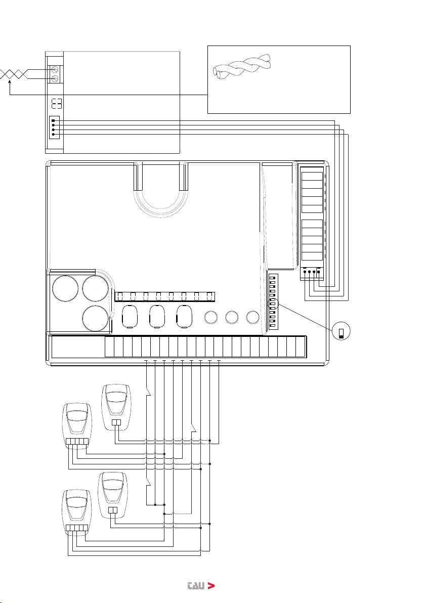
CONFIGURAZIONE MASTER/SLAVE CON 4 COPPIE DI FOTOCELLULE - CONFI-
GURATION MASTER / SLAVE WITH 4 PAIRS OF PHOTOCELLS
CONFIGURATION MASTER/SLAVE
AVEC 4 JEUX DE PHOTOCELLULES
3
T-COMM
T-COMM
A B
A B
Twisted cable max. 50 m
(NOT supplied in the
packaging)
Distanza/distance: < 10 m = section 1 mm2
> 10 m = section 1,5 mm2
K126MA
MASTER
ON
1 2 3 4 5 6 7 8 9 10 11 12
1
2
3
4
5
6
7
8
9
10
11
12
13
14
15
16
17
18
19
20
21
22
J4
7
K126MA
SLAVE
OFF
1 2 3 4 5 6 7 8 9 10 11 12
1
2
3
4
5
6
7
8
9
10
11
12
13
14
15
16
17
18
19
20
21
22
J4
7
Open/Close
Stop Release safety microswitch
Common
Common
Pedestrian
Int. Photocell
Fixed safety edge
-
+ 18V1
Ext. Photocell
Common
External
Photocells
RX
12345
TX
1 2
Internal
Photocells
RX
12345
TX
1 2
Stop R. S. M.
Common
Common
Int. Photocell
Fixed safety edge
-
+ 18V1
Ext. Photocell
Common
RX
12345
TX
1 2
RX
12345
TX
1 2
MASTER/SLAVE-KONFIGURATION MIT 4 FOTOZELLENPAAREN - CONFIGURA-
CIÓN MASTER/SLAVE CON 4 PARES DE FOTOCÉLULAS
4
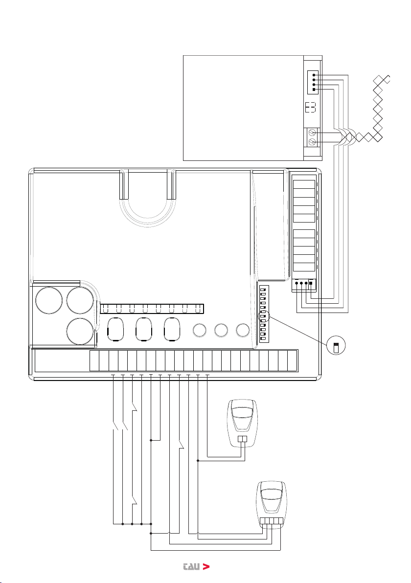
CONFIGURAZIONE MASTER/SLAVE CON 2 COPPIE DI FOTOCELLULE - CONFI-
GURATION MASTER / SLAVE WITH 2 PAIRS OF PHOTOCELLS
CONFIGURATION MASTER/SLAVE
AVEC 2 JEUX DE PHOTOCELLULES
T-COMM
T-COMM
A B
A B
K126MA
MASTER
ON
1 2 3 4 5 6 7 8 9 10 11 12
1
2
3
4
5
6
7
8
9
10
11
12
13
14
15
16
17
18
19
20
21
22
J4
7
K126MA
SLAVE
OFF
1 2 3 4 5 6 7 8 9 10 11 12
1
2
3
4
5
6
7
8
9
10
11
12
13
14
15
16
17
18
19
20
21
22
J4
7
Open/Close
Stop Release safety microswitch
Common
Common
Pedestrian
Ext. Photocell
Fixed safety edge
-
+ 18V
1
Common
External
Photocells
TX
1 2
Internal
Photocells
RX
12345
Stop R. S. M.
Common
Common
Int. Photocell
Fixed safety edge
-
+ 18V
1
Common
TX
1 2
RX
12345
Twisted cable max. 50 m
(NOT supplied in the
packaging)
Distanza/distance: < 10 m = section 1 mm2
> 10 m = section 1,5 mm2

5
MASTER/SLAVE-KONFIGURATION MIT 2 FOTOZELLENPAAREN - CONFIGURA-
CIÓN MASTER/SLAVE CON 2 PARES DE FOTOCÉLULAS
T-COMM
T-COMM
A B
A B
K126MA
MASTER
ON
1 2 3 4 5 6 7 8 9 10 11 12
1
2
3
4
5
6
7
8
9
10
11
12
13
14
15
16
17
18
19
20
21
22
J4
7
K126MA
SLAVE
OFF
1 2 3 4 5 6 7 8 9 10 11 12
1
2
3
4
5
6
7
8
9
10
11
12
13
14
15
16
17
18
19
20
21
22
J4
7
Open/Close
Stop Release safety microswitch
Common
Common
Pedestrian
Ext. Photocell
Fixed safety edge
-
+ 18V
1
Common
External
Photocells
TX
1 2
Internal
Photocells
RX
12345
Stop R. S. M.
Common
Common
Int. Photocell
Fixed safety edge
-
+ 18V
1
Common
TX
1 2
RX
12345
Twisted cable max. 50 m
(NOT supplied in the
packaging)
Distanza/distance: < 10 m = section 1 mm2
> 10 m = section 1,5 mm2

6
CONFIGURAZIONE MASTER/SLAVE CON 2 COPPIE DI FOTOCELLULE - CONFI-
GURATION MASTER / SLAVE WITH 2 PAIRS OF PHOTOCELLS
CONFIGURATION MASTER/SLAVE
AVEC 2 JEUX DE PHOTOCELLULES
T-COMM
T-COMM
A B
A B
K206MA
MASTER
ON
1 2 3 4 5 6 7 8 9 10 11 12
1
2
3
4
5
6
7
8
9
10
11
12
13
14
15
16
17
18
19
20
21
22
J4
7
K206MA
SLAVE
OFF
1 2 3 4 5 6 7 8 9 10 11 12
1
2
3
4
5
6
7
8
9
10
11
12
13
14
15
16
17
18
19
20
21
22
J4
7
Master
Photocells
Slave
Photocells
Open/Close
Stop
Common
Common
Open
Close
Fixed safety edge
- 0 V
+ 18 V
Photocell (N.C.)
Common
RX
12345
TX
1 2
Stop Swing away system switch (optional)
Stop
Common
Common
Close
Fixed safety edge
- 0 V
+ 18 V
Photocell (N.C.)
Common
RX
12345
TX
1 2
Stop Swing away system switch (optional)
Twisted cable max. 50 m
(NOT supplied in the
packaging)
Distanza/distance: < 10 m = section 1 mm2
> 10 m = section 1,5 mm2

7
MASTER/SLAVE-KONFIGURATION MIT 2 FOTOZELLENPAAREN - CONFIGURA-
CIÓN MASTER/SLAVE CON 2 PARES DE FOTOCÉLULAS
T-COMM
T-COMM
A B
A B
K206MA
MASTER
ON
1 2 3 4 5 6 7 8 9 10 11 12
1
2
3
4
5
6
7
8
9
10
11
12
13
14
15
16
17
18
19
20
21
22
J4
7
K206MA
SLAVE
OFF
1 2 3 4 5 6 7 8 9 10 11 12
1
2
3
4
5
6
7
8
9
10
11
12
13
14
15
16
17
18
19
20
21
22
J4
7
Master
Photocells
Slave
Photocells
Open/Close
Stop
Common
Common
Open
Close
Fixed safety edge
- 0 V
+ 18 V
Photocell (N.C.)
Common
RX
12345
TX
1 2
Stop Swing away system switch (optional)
Stop
Common
Common
Close
Fixed safety edge
- 0 V
+ 18 V
Photocell (N.C.)
Common
RX
12345
TX
1 2
Stop Swing away system switch (optional)
Twisted cable max. 50 m
(NOT supplied in the
packaging)
Distanza/distance: < 10 m = section 1 mm2
> 10 m = section 1,5 mm2

8
ITALIANO
Introduzione
Il presente manuale è destinato solamente al personale tecnico qualicato per l’installazione.
Nessuna informazione contenuta nel presente fascicolo può essere considerata d’interesse per
l’utilizzatore nale. Questo manuale è allegato all’interfaccia seriale T-COMM, non deve pertan-
to essere utilizzato per prodotti diversi!
Avvertenze:
L’interfaccia seriale T-COMM è progettata per la gestione di 2 automazioni simultanemente.
Le centrali di comando vengono collegate tra loro attraverso l’interfaccia seriale T-COMM, sin-
cronizzando i movimenti delle due automazioni rendendole, di fatto, un’unica installazione.
Ogni altro uso è improprio e, quindi, vietato dalle normative vigenti.
Nella progettazione delle proprie apparecchiature, TAU rispetta le normative applicabili al pro-
dotto (vedere la dichiarazione di conformità allegata); è fondamentale che anche l’installatore,
nel realizzare gli impianti, prosegua nel rispetto scrupoloso delle norme.
Personale non qualicato o non a conoscenza delle normative applicabili alla categoria dei “can-
celli e porte automatiche” deve assolutamente astenersi dall’eseguire installazioni ed impianti.
Chi non rispetta le normative è responsabile dei danni che l’impianto potrà causare!
Si consiglia di leggere attentamente tutte le istruzioni prima di procedere con l’installazione.
CARATTERISTICHE GENERALI
Il prodotto è progettato e costruito interamente dalla TAU S.r.l., risponde alle vigenti nor-
me di sicurezza.
Garanzia 24 mesi salvo manomissioni.
Le prestazioni indicate hanno validità solo se l’installazione del prodotto viene eseguita
correttamente, rispettando le indicazioni tecniche riportate in questo manuale d’istruzioni.
INTERFACCIA SERIALE RS485 T-COMM
L’utilizzo dell’interfaccia seriale T-COMM permette a 2 centrali di comando di altrettante automa-
zioni di comunicare tra loro in modalità MASTER/SLAVE.
Una centrale di comando deve essere impostata come MASTER, la seconda si congura automa-
ticamente come SLAVE al primo impulso inviato dalla centrale MASTER (vedi sez. “Installazione
interfaccia seriale RS485 T-COMM”). La centrale MASTER assume il comando logico del sistema.
È utilizzabile con tutte le centrali (per un motore) della serie DIAMOND.
CONTENUTO DELLA CONFEZIONE
- n°2 interfacce seriali RS485;
- n°2 cavi di connessione (centrale di comando - interfaccia seriale RS485) a 4 poli.
CONSIDERAZIONI PRELIMINARI
- I comandi (PEDONALE, APRE, APRE/CHIUDE, STOP) devono essere collegati solo nella
centrale MASTER.
- La radio ricevente va programmata solo nella centrale MASTER.
- Le fotocellule possono essere collegate sia nella centrale MASTER che nella centrale SLAVE.
- I bordi sensibili possono essere collegate sia nella centrale MASTER che nella centrale SLAVE
(se non vengono utilizzati, ponticellare i relativi ingressi).
- Il rilevamento ostacoli è indipendente su ciascuna centrale di comando.
- Impostare in maniera indipendente su ogni centrale di comando il modello “automazione”
(dip-switches 9, 10 e 11).
- Una volta impostata la comunicazione MASTER/SLAVE il sistema diventerà un’unica auto-
mazione, pertanto non sarà possibile azionare solamente una o l’altra automazione singo-
larmente.

9
ITALIANO
INSTALLAZIONE INTERFACCIA SERIALE RS485 T-COMM
(K206MA dalla versione v5.24 - K126MA dalla versione v5.14)
Per una corretta installazione, procedere come segue:
1_ Vericare che il dip-switch 7 di entrambe le centrali sia in posizione OFF. All’occorrenza
porre in OFF entrambi i dip-switches 7.
2_ Eseguire le procedure di SETUP di entrambe le automazioni.
3_ Porre il dip-switch 7 di una sola centrale in posizione ON, questa funzionerà da centrale MA-
STER. N.b. La seconda funzionerà automaticamente da centrale SLAVE senza interventi.
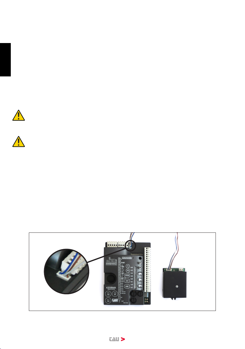
4_ Collegare ora le due interfacce alle centrali di comando utilizzando i cavi di connessione a 4
poli forniti nella confezione.
5_ Collegare tra loro le due interfacce per mezzo di un cavo twistato bipolare con sezione mini-
ma di 1 mm² (non fornito nella confezione).
6_ Testare il collegamento premendo il pulsante “PROG” sulla centrale MASTER.
ATTENZIONE: in congurazione MASTER/SLAVE, le funzioni dei dip-switch dal n°
1 al n° 8 sono attive solo nella centrale MASTER (i settaggi di questi dip-switches
sulla centrale SLAVE non hanno inuenza). I dip-swithes dal n° 9 al n° 12 sono in
uso su entrambe le centrali.
ATTENZIONE: nel caso si renda necessario modicare i parametri di lavoro tramite
TAUPROG su una centrale congurata come Master porre in OFF il dip-switch 7,
collegare il TAUPROG, regolare i parametri, scollegare il TAUPROG e riportare in
ON il dip-switch 7.
IMPORTANTE: quando la centrale MASTER va in stand-by (modalità basso consumo, J6
non ponticellato) la comunicazione tra le centrali non è attiva e la centrale SLAVE segnalerà
uno stato sconosciuto, che in questo caso è irrilevante.
In congurazione MASTER/SLAVE memorizzare i radiocomandi solo sulla ricevente della cen-
trale MASTER.
MALFUNZIONAMENTI: POSSIBILI CAUSE E RIMEDI
Le automazioni sono ferme
a- errore comunicazione master/slave
(il led DL8 della centrale MASTER emette 6 lampeggi di colore giallo);
Vericare il cablaggio tra le centrali, vericare l’ecienza della centrale slave (fusibili),
vericare l’ecienza delle schede di interfaccia;
Nelle pagine seguenti riportiamo gli schemi di collegamento in modalità MASTER/SLAVE per
K126MA a 2 e 4 coppie di fotocellule e K206MA con 2 coppie di fotocellule.

10
ITALIANO
DICHIARAZIONE DI INCORPORAZIONE DEL COSTRUTTORE
(ai sensi della Direttiva Europea 2006/42/CE AlI. II.B)
Fabbricante: TAU S.r.l.
Indirizzo: Via E. Fermi, 43
36066 Sandrigo (Vi)
ITALIA
Dichiara sotto la propria responsabilità che il prodotto: Interfaccia seriale RS485 T-COMM
realizzato per: Gestire due automazioni simultanemente
per uso in ambiente: Residenziale / Condominiale / Industriale
completo di: n°2 interfacce seriali e n°2 cavi di connessione a
4 poli
Modello: T-COMM
Tipo: T-COMM
Numero di serie: vedi etichetta argentata
Denominazione commerciale: Interfaccia seriale RS485
È realizzato per essere incorporato su una chiusura (cancello scorrevole) o per essere assemblato con altri dispositivi
al ne di movimentare una tale chiusura per costituire una macchine ai sensi della Direttiva Macchine 2006/42/CE.
Dichiara inoltre che questo prodotto è conforme ai requisiti essenziali di sicurezza delle seguenti ulteriori direttive
CEE:
- 2006/95/CE Direttiva Bassa Tensione
- 2004/108/CE Direttiva Compatibilità Elettromagnetica
ed, ove richiesto, alla Direttiva:
- 1999/5/CE Apparecchiature Radio e apparecchiature terminali di telecomunicazione
Dichiara inoltre che non è consentito mettere in servizio il macchinario no a che la macchina in cui sarà
incorporato o di cui diverrà componente sia stata identicata e ne sia stata dichiarata la conformità alle condizioni
della Direttiva 2006/42/CE.
Si impegna a trasmettere, su richiesta adeguatamente motivata delle autorità nazionali, informazioni pertinenti sulle
quasi-macchine.
Sandrigo, 07/07/2016
Il Rappresentante Legale
_________________________________________
Loris Virgilio Danieli
Nome e indirizzo della persona autorizzata a costituire la documentazione tecnica pertinente:
Loris Virgilio Danieli - via E. Fermi, 43 - 36066 Sandrigo (Vi) Italia

11
ENGLISH
Introduction
This manual is intended only for qualied technical personnel
No information contained in this manual can be considered of interest for the end user.
This manual is attached to the serial T-COMM, it should therefore not be used for dierent pro-
ducts.
WARNINGS:
The serial interface T-COMM is designed for the management of 2 automations simultaneously.
The control units are connected to each other via the serial interface T-COMM, synchronizing
the movements of the two automated systems making them, in fact, a single installation.
Any other use is improper and, therefore, prohibited by regulation.
In the design of its equipment, TAU observes all applicable standards (see the attached decla-
ration of conformity); it is fundamental that the installer, in establishing installations, continue in
strict compliance with the rules.
Unqualied personnel or unaware of the standards applicable to the “automatic gates and do-
ors” must absolutely refrain install systems.
Those who break the regulations are liable for damages that the system may cause!
You should carefully read all instructions before proceeding with the installation.
GENERAL CHARACTERISTICS
The product is designed and manufactured by TAU Srl, it complies with current safety
standards.
Warranty 24 months (if not tampered with).
The performances shown are valid only if the product installation is successful, within
the technical information given in this instruction manual.
RS485 SERIAL INTERFACE T-COMM
The serial interface T-COMM allows at 2 control panels to communicate with each other in MA-
STER / SLAVE mode.
A control unit must be set as MASTER, the second is automatically congured as SLAVE at the
rst pulse sent from the MASTER unit (see sect. “Installation RS485 serial interface T-COMM”).
The MASTER unit assumes the logical system control.
It is usable with all the control panels (for a single motor) of the DIAMOND series.
PACKAGE CONTENTS
- N ° 2 serial interfaces RS485;
- 2 connecting cables (control unit - RS485 serial interface) - 4 poles.
PRELIMINARY ADVICES
- ICommands (PEDESTRIAN, OPEN, OPEN / CLOSE, STOP) must be connected only in the
MASTER unit.
- The radio receiver must be programmed only in the MASTER unit.
- The photocells can be connected both in the MASTER or in the SLAVE control panel.
- The safety edges can be connected both in the MASTER or in the SLAVE control panel (if
not used, jumper the corresponding inputs).
- The obstacle detection is independent in each control unit.
- Set independently, on each control panel, the “automation” model (dip-switches 9, 10 ,11).
- After setting the MASTER / SLAVE communication, the system will become a single
automation,therefore it will not possible to operate only a single automation individually.
12
ENGLISH
INSTALLATION RS485 SERIAL INTERFACE T-COMM
(K206MA from version v5.24 - K126MA from version v5.14)
For proper installation, follow these steps:
1_ Veriy that the dip-switch 7 of both control panels is in the OFF position. If necessary, put in
OFF both.
2_ Perform SETUP procedure of both the automations.
3_ Put the dip-switch 7 of a one control panel in ON, this will act as MASTER unit. N.B. The
second will run automatically in SLAVE without any intervent.
4_ Connect now the two interfaces to the control panels by using the 4-pole connection cables
provided in the package.
5_ Connect together the two interfaces by means of a bipolar twisted cable with minimum sec-
tion of 1 mm² (not supplied in the pack).
6_ Try the connection between the devices by pressing the “PROG” button on the MASTER
unit.
WARNING:
In MASTER / SLAVE conguration, the functions of the dip-switches from N.1 to
N.8 are active only in the MASTER unit (the settings of these dip-switches on the
SLAVE have no inuence).
The dip-switches from N.9 to N.12 are in use on both control panels.
WARNING: In case should it be necessary to change the working parameters via
TAUPROG on a control panel congured as Master, put in OFF the dip-switch 7,
connect the TAUPROG and adjust the parameters, then disconnect the TAUPROG
and re-put in ON the dip-switch 7.
IMPORTANT: When the MASTER unit goes into stand-by mode (low power mode, jumper
J6 not bridged) the communication between the control panels is not active and the SLAVE
will signal an unknown state which, in this case, is irrelevant.
In MASTER / SLAVE conguration, store remote controls only on the MASTER unit.
MALFUNCTIONS: POSSIBLE CAUSES AND SOLUTIONS
Automations are o
a- Error Master / Slave Communication
(LED DL8 on the MASTER giving 6 ashes yellow);
Check the wiring between the control panels, check the eciency of the SLAVE (fuses),
check the eciency of the two interfaces.
In the following pages we list the connection diagrams in MASTER / SLAVE mode for
K126MA with 2 and 4 pairs of photocells and K206MA with 2 pairs of photocells.

13
MANUFACTURER’S DECLARATION OF INCORPORATION
(in accordance with European Directive 2006/42/EC App. II.B)
Manufacturer: TAU S.r.l.
Address: Via E. Fermi, 43
36066 Sandrigo (Vi)
ITALY
Declares under its sole responsibility, that the product: RS485 serial interface
designed for automatic movement of: Manage two automations simoultaneously
for use in a: Residential / Communities
complete with: No. 2 serial interfaces and n ° 2 cables 4 poles
Model: T-COMM
Type: T-COMM
Serial number: see silver label
Commercial name: RS485 serial interface
Has been produced for incorporation on an access point (swing gate) of for assembly with other devices used to
move such an access point, to constitute a machine in accordance with the Machinery Directive 2006/42/EC.
Also declares that this product complies with the essential safety requirements of the following EEC directives:
- 2006/95/EC Low Voltage Directive
- 2004/108/EC Electromagnetic Compatibility Directive
and, where required, with the Directive:
- 1999/5/CE Radio equipment and telecommunications terminal equipment
Also declares that it is not permitted to start up the machine until the machine in which it is incorporated or of
which it will be a component has been identied with the relative declaration of conformity with the provisions of
Directive 2006/42/EC.
The manufacturer undertakes to provide, on suciently motivated request by national authorities, all information
pertinent to the quasi-machinery.
Sandrigo, 07/07/2016
Legal Representative
_________________________________________
Loris Virgilio Danieli
Name and address of person authorised to draw up all pertinent technical documentation:
Loris Virgilio Danieli - via E. Fermi, 43 - 36066 Sandrigo (Vi) Italy
ENGLISH

14
DEUTSCH
Einleitung
Diese Bedienungsanleitung richtet sich nur an das mit der Installation betraute technische Fa-
chpersonal. Keine der in dieser Broschüre enthaltenen Informationen können als für den End-
verbraucher von Interesse betrachtet werden. Diese Anleitung liegt der seriellen Schnittstelle
T-COMM bei und darf daher nicht für andere Produkte verwendet werden!
Hinweis:
Die serielle Schnittstelle T-COMM ist für die simultane Steuerung von zwei Automatisierungen
ausgelegt. Die Steuergeräte werden über die serielle Schnittstelle T-COMM zusammengeschal-
tet, so dass die Bewegungen der beiden Automatisierungen synchronisiert und diese so zu
einer einzigen Installation werden. Jegliche anderen Verwendungen gelten als unsachgemäß
und damit von den geltenden Bestimmungen untersagt.
TAU beachtet bei der Entwicklung ihrer Produkte die für das Produkt geltenden Bestimmungen
(siehe Konformitätserklärung in der Anlage). Es ist von ausschlaggebender Bedeutung, dass
auch der Installateur beim Einrichten der Systeme diese Bestimmungen genau einhält.
Nicht qualiziertes oder Personal, das die für die Kategorie “Automatische Tore und Türen” gel-
tenden gesetzlichen Bestimmungen nicht kennt, muss sich der Einrichtung von Installationen
und Systemen unbedingt enthalten.
Wer sich nicht an die geltenden Bestimmungen hält, haftet für die Schäden, die das Sy-
stem verursachen kann!
Es wird empfohlen, vor der Installation alle Anweisungen aufmerksam zu lesen.
ALLGEMEINE MERKMALE
Das Produkt wurde in vollem Umfang von TAU S.r.l. entwickelt und hergestellt und
entspricht den geltenden Sicherheitsbestimmungen.
Die Garantie beträgt 24 Monate, unbefugte Eingrie ausgenommen.
Die angegebenen Leistungen beziehen sich nur auf die korrekt ausgeführte Installation des
Produkts unter Einhaltung der in dieser Anleitung aufgeführten technischen Hinweise.
SERIELLE SCHNITTSTELLE RS485 T-COMM
Der Einsatz der seriellen Schnittstelle T-COMM gestattet es zwei Steuergeräten für ebenso viele
Automatisierungen, miteinander nach dem MASTER/SLAVE-Prinzip zu kommunizieren.
Ein Steuergerät muss als MASTER ausgelegt werden. Das zweite wird beim ersten von der
MASTER-Einheit versandten Impuls automatisch als SLAVE konguriert (siehe Abschnitt “Instal-
lation der seriellen Schnittstelle RS485 T-COMM”). Das Master-Gerät übernimmt die logische
Steuerung des Systems.
Die Verwendung ist mit allen Steuergeräten (für einen Motor) der Reihe DIAMOND möglich.
INHALT DER VERPACKUNG
- 2 serielle RS485-Schnittstellen;
- 2 4-polige Anschlusskabel (Steuergerät - serielle RS485-Schnittstelle).
VORBEMERKUNGEN
- Die Steuerungen (FUSSGÄNGER, ÖFFNET, ÖFFNET/SCHLIESST, STOPP) dürfen nur an
das MASTER-Gerät angeschlossen sein.
- Der Empfänger ist nur im MASTER-Gerät zu programmieren.
- Die Fotozellen können sowohl im MASTER- als auch im SLAVE-Gerät angeschlossen werden.
- Die Tastleisten können sowohl im MASTER- als auch im SLAVE-Gerät angeschlossen werden
(wenn sie nicht verwendet werden, die jeweiligen Eingänge überbrücken).
- Die Erfassung von Hindernissen erfolgt auf jedem Steuergerät unabhängig.
- Auf jedem Steuergerät das Modell der “Automatisierung” unabhängig eingeben (Dip-Switch 9, 10 und 11).
- Sobald die MASTER/SLAVE-Kommunikation eingerichtet ist, wird das System zu einer

15
DEUTSCH
einzigen Automatisierung, daher ist es nicht mehr möglich, nur die eine oder die andere
Automatisierung einzeln zu bedienen.
INSTALLATION DER SERIELLEN SCHNITTSTELLE RS485 T-COMM
(K206MA ab der Version v5.24 - K126MA ab der Version v5.14)
Für eine korrekte Installation wie folgt vorgehen:
1_ Überprüfen, ob der Dip-Switch 7 beider Steuergeräte auf OFF steht. Gegebenenfalls beide
Dip-Switches 7 auf OFF stellen.
2_ Die SETUP-Vorgänge beider Automatisierungen ausführen.
3_ Den Dip-Switch 7 nur eines Steuergeräts auf ON stellen. Dieses funktioniert dann als MA-
STER-Steuergerät. Anm.: Das zweite Steuergerät funktioniert ohne jegliche Eingrie auto-
matisch als SLAVE-Gerät.
4_ Nun die beiden Schnittstellen an die Steuergeräte anschließen und dazu die im Lieferumfang
enthaltenen 4-poligen Anschlusskabel verwenden.
5_ Die beiden Schnittstellen mit Hilfe eines zweipoligen Twisted-Pair-Kabels mit einem Quer-
schnitt von mindestens 1 mm² anschließen (nicht im Lieferumfang enthalten).
6_ Den Anschluss durch Betätigen der Taste “PROG” auf dem MASTER-Gerät testen.
ACHTUNG: In der MASTER/SLAVE-Konguration sind die Funktionen der Dip-
Switches 1 bis 8 nur im MASTER-Gerät aktiv (die Einstellungen dieser Dip-Switches
auf dem SLAVE-Gerät haben keinen Einuss). Die Dip-Switches 9 bis 12 sind auf
beiden Geräten in Gebrauch.
ACHTUNG: Sollte es notwendig werden, die Betriebsparameter über TAUPROG auf
einem als Master programmierten Gerät zu ändern, den Dip-Switch auf OFF stellen,
TAUPROG anschließen, die Parameter einstellen, TAUPROG abtrennen und den
Dip-Switch 7 wieder auf ON stellen.
WICHTIG: Wenn sich das MASTER-Gerät im Standby bende (Betriebsart mit geringem
Verbrauch, J6 nicht überbrückt) ist die Kommunikation zwischen den Steuergeräten nicht aktiv
und das SLAVE-Gerät signalisiert einen unbekannten Status, der in diesem Fall irrelevant ist.
In der MASTER/SLAVE-Konguration die Fernsteuerungen nur auf dem Empfänger des MA-
STER-Geräts speichern.
FUNKTIONSSTÖRUNGEN: MÖGLICHE URSACHEN UND BEHEBUNG
Die Automatisierungen reagieren nicht
a- Kommunikationsfehler Master/Slave
(die Led DL8 des MASTER-Steuergeräts sendet 6 gelbe Blinkzeichen aus);
Überprüfen Sie die Verkabelung zwischen den Steuergeräten, die Funktionstauglichkeit des
Steuergeräts Slave (Sicherungen) und die Funktionstauglichkeit der Schnittstellenkarten.
Auf den nachstehenden Seiten werden die Anschlusspläne in der MASTER/SLAVE-Kongura-
tion für K126MA mit 2 und 4 Fotozellenpaaren und K206MA mit 2 Fotozellenpaaren aufgeführt.

16
INTEGRIERUNGSERKLÄRUNG DES HERSTELLERS
(gemäß der Europäischen Richtlinie 2006/42/EG Anl. II.B)
Hersteller: TAU S.r.l.
Adresse: Via E. Fermi, 43
36066 Sandrigo (Vi)
ITALY
Erklärt unter seiner Haftung, dass das Produkt: Elektronische Steuerung
für die automatische Bewegung von: Gestire due automazioni simultanemente
für eine Anwendung: Privat / Gewerbe
Einschließlich: n°2 interfacce seriali e n°2 cavi di connessione a
4 poli
Modell: T-COMM
Typ: T-COMM
Seriennummer: siehe Silberetikette
Handelsbezeichnung: Serielle Schnittstelle RS485
ausgeführt wurde, um in einen Verschluss integriert zu werden (Drehtore) oder um mit anderen Vorrichtungen
kombiniert zu werden, um diesen Verschluss zu bewegen, und somit gemäß der Maschinenrichtlinie 2006/42/EG
eine Maschine darstellt.
Außerdem erklärt er, dass dieses Produkt den grundsätzlichen Sicherheitseigenschaften der folgenden Richtlini-
en EWG entspricht:
- 2006/95/EG Niederspannungsrichtlinie
- 2004/108/EG Richtlinie für elektromagnetische Kompatibilität
Und wo gefordert, der Richtlinie:
- 1999/5/CE Radio equipment and telecommunications terminal equipment
Außerdem wird erklärt, dass es nicht zugelassen ist, die Vorrichtung in Betrieb zu setzen, bis die Maschine, in
die sie integriert wird oder deren Bestandteil sie sein wird, identiziert und die Konformität gegenüber dem Inhalt
der Richtlinie 2006/42/EG erklärt wurde.
Er verpichtet sich, auf ausdrücklichen Wunsch der nationalen Behörden, Informationen über die Fastmaschinen
zu übersenden.
Sandrigo, 07/07/2016
Der gesetzliche Vertreter
_________________________________________
Loris Virgilio Danieli
Name und Adresse der beauftragten Person zur Vorlegung der zugehörigen technischen Unterlagen:
Loris Virgilio Danieli - via E. Fermi, 43 - 36066 Sandrigo (Vi) Italy
DEUTSCH

17
FRANÇAIS
Introduction
Ce mode d’emploi n’est adressé qu’aux techniciens agréés pour l’installation.
Aucune information y contenue n’est intéressante pour l’utilisateur nal. Ce mode d’emploi est
joint à l’activateur T-COMM. Il ne doit donc pas être utilisé pour des produits diérents!
AVERTISSEMENTS:
L’activateur T-COMM est conçu pour contrôler deux automatismes simultanément.
L’activateur T-COMM rélie les centrales de commande en synchronisant les mouvements des
deux automatismes, qui deviennent en fait une seule installation.
Toute autre utilisation est impropre et donc interdite par les normes en vigueur.
Dans le projet de ses appareils, TAU respecte les normes applicables au produit (voir la décla-
ration de conformité ci-jointe). Il est d’une importance fondamentale que l’installateur, de sa part,
respecte scrupuleusement les normes de sécurité dans la réalisation des installations.
Tout personnel non qualié ou ne connaissant pas les normes applicables à la catégorie des
“portails et portes automatiques” doit absolument s’abstenir d’eectuer toute installation.
Qui ne respecte pas les normes est responsable des dommages que l’installation pourra causer!
Nous conseillons de lire attentivemente ce mode d’emploi avant de procéder à l’installation.
CARACTÉRISTIQUES GÉNÉRALES
Le produit est entièrement conçu et réalisé par TAU srl dans le respect des normes de
sécurité en vigueur.
Garantie pendant 24 mois, tout endommagement accidentel excepté.
Les performances de l’activateur indiquées ne sont possibles que grâce à une correcte
installation du produit, dans le respect des indications techniques fournies dans ce
mode d’emploi.
ACTIVATEUR RS485 T-COMM
L’activateur T-COMM permet à deux centrales de commande de deux diérentes automations
de se connecter au moyen du système MASTER/SLAVE.
La première impulsion envoyée par la centrale de commande MASTER à l’autre centrale en
permet la conguration automatique en tant que SLAVE (voir la section “installation activateur
RS485 T-COMM).
La centrale MASTER commande la logique du système. Il est possibile de l’utiliser avec toute
centrale pour un moteur de la série DIAMOND.
CONTENU DU COLIS
- n°2 activateurs RS485;
- n°2 câbles de connection (centrale de commande - activateur RS485) à 4 pôles.
INFORMATIONS PRÉLIMINAIRES
- Les commandes (PIÉTON, OUVRE, OUVRE/FERME, STOP) doivent être connectées uni-
quement sur la centrale MASTER.
- Le récepteur radio ne doit être programmé que sur la centrale MASTER.
- Les photocellules peuvent être connectées sur la centrale MASTER aussi bien que sur la
centrale SLAVE.
- Les barres palpeuses peuvent être connectées sur la centrale MASTER aussi bien que sur
la centrale SLAVE.(Mettre en pont les bornes si non utilisées).
- La détection des obstacles est indépendante sur chaque centrale de commande.
- Régler séparément sur chaque centrale de commande le modèle “automation” (dip-switches 9, 10 et 11).
- Après avoir réglé la communication entre centrales MASTER/SLAVE, le système sera en
fait une seule automation. Il ne sera donc pas possible d’activer séparément l’une ou l’autre
automation.

18
FRANÇAIS
INSTALLATION ACTIVATEUR RS485 T-COMM
(K206MA partir de la version v5.24 - K126MA partir de la version v5.14)
Suivre la procédure indiquée ci-dessous pour une correcte installation:
1_ Vérier que le dip-switch 7 des deux centrales soit en position OFF. En cas contraire, dépla-
cer les deux dip-switches 7 en position OFF.
2_ Eectuer la procédure de SETUP des deux automations.
3_ Déplacer le dip-switch 7 d’une seule centrale en position ON. Elle fera fonction de centrale
MASTER.
N.b. La deuxième centrale sera automatiquemente congurée en tant que centrale SLAVE
sans aucune intervention.
4_ Connecter les deux activateurs aux centrales de commande en utilisant les câbles de con-
nexion à 4 pôles fournis.
5_ Connecter les deux activateurs entre eux au moyen d’un câble bipolaire twisté avec section
minimale de 1 mm² (pas fourni dans le colis).
6_ Vérier la connection en appuyant sul le bouton “PROG” de la centrale MASTER.
ATTENTION: en MASTER/SLAVE mode, les fonctions des dip-switches du n° 1 au n°
8 ne sont activées que sur la centrale MASTER (le réglage des mêmes dip-switches
sur la centrale SLAVE n’a pas d’importance). Les dip-swithes du n° 9 au n° 12 sont
activés sur les deux centrales.
ATTENTION: Pour toute variation des paramètres de travail au moyen du TAUPROG
sur une centrale MASTER, déplacer le dip switch 7 en OFF, connecter le TAUPROG,
régler les paramètres, déconnecter le TAUPROG et déplacer à nouveau le dip-switch
7 en ON.
IMPORTANT: lorsque la centrale MASTER est en veille (mode basse consommation, J6
non mis en pont) la communication entre les deux centrales n’est pas activée et la centrale
SLAVE va signaler un état inconnu qui n’a pas d’importance en ce cas.
En MASTER/SLAVE mode, il ne faut mémoriser les émetteurs que sur la centrale MASTER.
PROBLÈMES DE FONCTIONNEMENT : CAUSES POSSIBLES ET REMÈDES
Les automatismes ne démarrent pas
a- erreur de communcation master/slave
(le led DL8 de la centrale MASTER est jaune et clignote 6 fois);
Vérier le câblage entre les centrales, vérier les fusibles de la centrale slave, vérier le
fonctionnemente de la carte d’interface;
Dans les pages suivantes Vous trouverez les schémas de câblage master/slave pour la
centrale K126MA avec 2 et 4 jeux de photocellules et pour la centrale K206MA avec 2 jeux
de photocellules.

19
DÉCLARATION D’INCORPORATION DU FABRICANT
(conformément à la Directive européenne 2006/42/CE Annexe II.B)
Fabricant : TAU S.r.l.
Adresse : Via E. Fermi, 43
36066 Sandrigo (Vi)
ITALY
Déclare sous sa propre responsabilité que le produit : Activateur RS485
réalisé pour le mouvement automatique de : Contrôler deux automations simultanément
pour l’utilisation en milieu : Résidentiel / Intensif
muni de : n°2 activateurs et n°2 câbles de connexion à 4
pôles
Modèle : TCOMM
Type : TCOMM
Numéro de série : voir étiquette argentée
Appellation commerciale : Activateur RS485
est réalisé pour être incorporé sur une fermeture (portail à battant) ou pour être assemblé avec d’autres dispositifs
an de manœuvrer cette fermeture pour constituer une machine au sens de la Directive Machines 2006/42/CE.
Déclare d’autre part que ce produit est conforme aux exigences essentielles de sécurité des directives CEE sui-
vantes :
- 2006/95/CE Directive Basse Tension
- 2004/108/CE Directive Compatibilité Électromagnétique
et, si requis, à la Directive:
- 1999/5/CE Équipements hertziens et équipements terminaux de télécommunication
Le Fabricant déclare également qu’il n’est pas permis de mettre en service l’appareil tant que la machine dans
laquelle il sera incorporé ou dont il deviendra composant n’a pas été identiée et que sa conformité aux conditions
de la Directive 2006/42/CE n’a pas été déclarée.
Il s’engage à transmettre, sur demande dûment motivée des autorités nationales, des informations pertinentes sur
les quasi-machines.
Sandrigo, 07/07/2016
Le Représentant légal
_________________________________________
Loris Virgilio Danieli
Nom et adresse de la personne autorisée à constituer la documentation technique pertinente :
Loris Virgilio Danieli - via E. Fermi, 43 - 36066 Sandrigo (Vi) Italy
FRANÇAIS

20
ESPAÑOL
Introducción
Este manual está dirigido sólo a personal técnico cualicado para la instalación.
Ninguna información contenida en este manual puede ser considerada de interés para el usua-
rio nal. Este manual se adjunta a la interfaz serie T-COMM, y no se puede utilizar para pro-
ductos diferentes.
Advertencias:
La interfaz serie T-COMM está diseñada para la gestión de 2 automatismos simultáneamente.
Las centrales de mando están conectadas entre sí a través de la interfaz serie T-COMM, per-
mitiendo la sincronización de los movimientos de los dos automatismos, permitiendo, de hecho,
una única instalación.
Cualquier otro uso se considera impropio y, por lo tanto, prohibido conforme a las normas vigentes.
En el diseño de sus equipos, TAU respeta las normativas vigentes (ver la declaración de con-
formidad adjunta); es fundamental que el instalador, al realizar las instalaciones, continúe en el
estricto cumplimiento de las normas.
El personal no cualicado o sin conocimiento de las normas aplicables a las “puertas y puertas
automáticas” debe abstenerse absolutamente de realizar instalaciones.
Quienes no respeten las normas son responsables de los daños que la instalación puede causar.
Se aconseja leer cuidadosamente todas las instrucciones antes de proceder con la instalación.
CARACTERÍSTICAS GENERALES
El producto está diseñado y construido enteramente por TAU Srl, que cumple con las nor-
mas de seguridad vigentes.
Garantía 24 meses si no manipulado.
Las actuaciones que se muestran son válidas sólo si la instalación del producto se realiza cor-
rectamente, respetando la información técnica contenida en este manual de instrucciones.
INTERFAZ SERIE RS485 T-COMM
El uso de la interfaz serie T-COMM permite a 2 centrales de mando que accionan un número
igual de automatismos comunicarse en modo MASTER/SLAVE.
Una central de mando se debe congurar como MASTER, la segunda se congura automática-
mente como SLAVE en el primer impulso enviado por la central MASTER (ver secc. «Instalación de
la interfaz serie RS485 T-COMM»). La central MASTER se encarga del control lógico del sistema.
Es utilizable con todas las centrales (para un motor) de la serie DIAMOND.
CONTENIDO DEL PAQUETE
- n°2 interfaces serie RS485;
- n°2 cables de conexión (central de mando - interfaz serie RS485) de 4 polos.
OBSERVACIONES PRELIMINARES
- Los mandos (PEATONAL, ABRE, ABRE/CIERRA, STOP) se deben conectar solo en la central
MASTER.
- El receptor de radio se debe programar solo en la central MASTER.
- Las fotocélulas se pueden conectar tanto en la central MASTER y en la central SLAVE.
- Los bordes sensibles se pueden conectar tanto en la central MASTER y en la central SLAVE
(si no se utilizan, puentear las entradas relativas).
- La detección de obstáculos es independiente de cada central de mando.
- Establecer de forma independiente en cada central de mando el modelo «automatismo»
(dip-switch 9, 10 y 11).
- Tras congurar la comunicación MASTER/SLAVE, el sistema se convertirá en un único
automatismo, por lo que no será posible accionar solamente uno u otro automatismo inde-
pendientemente.
Table of contents
Languages:
Popular Recording Equipment manuals by other brands

Philips
Philips CDR800/00/17 Service manual

Dynasound
Dynasound DS3002 manual

Roland
Roland Compu Rhythm CR-68 owner's manual

Extron electronics
Extron electronics RGB 190F Specifications

Niles
Niles SSVC-2 Installation & operation guide

25-Seven Systems
25-Seven Systems program delay manager Operator's manual


